

General Description
The MAX6846–MAX6849 are a family of ultra-low-power
battery monitors with integrated microprocessor (µP)
supervisors. The user-adjustable battery monitors are
offered with single or dual low-battery output options that
can be used to signal when the battery is OK (enabling
full system operation), when the battery is low (for lowpower system operation), and when the battery is dead
(to disable system operation). These devices also have
an independent µP supervisor that monitors VCCand
provides an active-low reset output. A manual reset
function is available to reset the µP with a pushbutton.
The MAX6846–MAX6849 are ideal for single-cell lithiumion (Li+) or multicell alkaline/NiCd/NiMH applications.
When the battery voltage drops below each adjusted low
threshold, the low-battery outputs are asserted to alert
the system. When the voltage rises above the adjusted
high thresholds, the outputs are deasserted after a
150ms minimum timeout period, ensuring the voltages
have stabilized before power circuitry is activated or providing microprocessor reset timing.
These devices have user-adjustable battery threshold
voltages, providing a wide hysteresis range to prevent
chattering that can result due to battery recovery after
load removal. Single low-battery outputs are supplied
by the MAX6846/MAX6847 and dual low-battery outputs are supplied by the MAX6848/MAX6849. All battery monitors have open-drain low-battery outputs.
The MAX6846–MAX6849 monitor system voltages
(VCC) from 1.8V to 3.3V with seven fixed reset threshold
options. Each device is offered with two minimum reset
timeout periods of 150ms or 1200ms. The MAX6846/
MAX6848 are offered with an open-drain RESET output
and the MAX6847/MAX6849 are offered with a pushpull RESET output.
The MAX6846–MAX6849 are offered in a SOT23 package and are fully specified over a -40°C to +85°C temperature range.
Applications
Battery-Powered Systems (Single-Cell Li+ or
Multicell NiMH, NiCd, Alkaline)
Cell Phones/Cordless Phones
Portable Medical Devices
Digital Cameras
Pagers
PDAs
MP3 Players
Electronic Toys
Features
♦ User-Adjustable Thresholds for Monitoring
Single-Cell Li+ or Multicell Alkaline/NiCd/NiMH
Applications
♦ Single and Dual Low-Battery Output Options
♦ Independent µP Reset with Manual Reset
♦ Factory-Set Reset Thresholds for Monitoring 1.8V
to 3.3V Systems
♦ Available with 150ms (min) or 1.2s (min) V
CC
Reset Timeout Period Options
♦ 150ms (min) LBO Timeout Period
♦ Immune to Short-Battery Voltage Transients
♦ Low Current (2.5µA, typ at 3.6V)
♦ -40°C to +85°C Operating Temperature Range
♦ Small 8-Pin SOT23 Packages
MAX6846–MAX6849
Low-Power, Adjustable Battery Monitors with
Hysteresis and Integrated µP Reset
________________________________________________________________ Maxim Integrated Products 1
Pin Configurations
Ordering Information
19-2947; Rev 0; 7/03
For pricing, delivery, and ordering information, please contact Maxim/Dallas Direct! at
1-888-629-4642, or visit Maxim’s website at www.maxim-ic.com.
Note: The first “_” is the VCCreset threshold level, suffix found
in Table 1. The “_” after the D is a placeholder for the reset
timeout period suffix found in Table 2. All devices are available
in tape-and-reel only. There is a 2500 piece minimum order
increment for standard versions (see Standard Versions table).
Sample stock is typically held on standard versions only. Nonstandard versions require a minimum order increment of
10,000 pieces. Contact factory for availability.
查询MAX6846KARD3供应商
PART TEMP RANGE PIN-PACKAGE
MAX6846KA_D_-T -40°C to +85°C 8 SOT23-8
MAX6847KA_D_-T -40°C to +85°C 8 SOT23-8
MAX6848KA_D_-T -40°C to +85°C 8 SOT23-8
MAX6849KA_D_-T -40°C to +85°C 8 SOT23-8
TOP VIEW
V
LTHIN
1
DD
2
MAX6846
3
MAX6847
4
87V
6
5
CC
HTHINGND
MR
RESETLBO
LTHIN
LBOL
DD
2
MAX6848
3
MAX6849
4
1
V
SOT23
SOT23
87V
6
5
CC
HTHINGND
LBOH
RESET
MAX6846–MAX6849
Low-Power, Adjustable Battery Monitors with
Hysteresis and Integrated µP Reset
2 _______________________________________________________________________________________
ABSOLUTE MAXIMUM RATINGS
Stresses beyond those listed under “Absolute Maximum Ratings” may cause permanent damage to the device. These are stress ratings only, and functional
operation of the device at these or any other conditions beyond those indicated in the operational sections of the specifications is not implied. Exposure to
absolute maximum rating conditions for extended periods may affect device reliability.
*Applying 7V for a duration of 1ms does not damage the device.
V
DD
, VCCto GND....................................................-0.3V to +6V*
Open-Drain LBO, LBOH, LBOL to GND .................-0.3V to +6V*
Open-Drain RESET to GND ....................................-0.3V to +6V*
Push-Pull RESET to GND............................-0.3V to (V
CC
+ 0.3V)
HTHIN, LTHIN to GND................................-0.3V to (V
DD
+ 0.3V)
MR to GND .................................................-0.3V to (V
CC
+ 0.3V)
Input/Output Current, All Pins .............................................20mA
Continuous Power Dissipation (T
A
= +70°C)
8-Pin SOT23 (derate 8.9mW/°C above +70°C)............714mW
Operating Temperature Range .......................... -40°C to +85°C
Junction Temperature......................................................+150°C
Storage Temperature Range .............................-65°C to +150°C
Lead Temperature (soldering, 10s) .................................+300°C
ELECTRICAL CHARACTERISTICS
(VDD= 1.6V to 5.5V, VCC= 1.2V to 5.5V, TA= -40°C to +85°C, unless otherwise specified. Typical values are at TA= +25°C.) (Note 1)
VDD Operating Voltage Range V
VCC Operating Voltage Range V
VCC + VDD Supply Current ICC + I
MAX6846/MAX6847 VDD THRESHOLDS
HTHIN Threshold V
LTHIN Threshold V
MAX6848/MAX6849 VDD THRESHOLDS
HTHIN+ Threshold V
HTHIN- Threshold V
LTHIN+ Threshold V
LTHIN- Threshold V
MAX6846–MAX6849
HTHIN/LTHIN Leakage Current I
LBO , LBO L, LBO H Ti m eout P er i od t
LBO, LBOL, LBOH Delay Time t
LBO, LBOL, LBOH Output Low V
PARAMETER SYMBOL CONDITIONS MIN TYP MAX UNITS
DD
CC
HTH
LTH
HTH+
HTH-
LTH+
LTH-
LKG
LBOP
LBOD
OL
TA = 0°C to +85°C 1.0 5.5
TA = -40°C to +85°C 1.2 5.5
DDVDD
= 3.6V, VCC = 3.3V, no load (Note 2) 2.5 7 µA
HTHIN rising, LBO is deasserted when
HTHIN rises above V
LTHIN falling, LBO is asserted when LTHIN
falls below V
HTHIN rising, LBOH is deasserted when
HTHIN rises above V
HTHIN falling, LBOH is asserted when
HTHIN falls below V
LTHIN rising, LBOL is deasserted when
LTHIN rises above V
LTHIN falling, LBOL is asserted when
LTHIN falls below V
V
HTHIN
HTHIN/LTHIN rising above threshold 150 225 300 ms
HTHIN/LTHIN falling below threshold 100 µs
(VDD or VCC) ≥ 1.2V, I
low
(VDD or VCC) ≥ 1.6V, I
asserted low
(VDD or VCC) ≥ 2.7V, I
asserted low
(VDD or VCC) ≥ 4.5V, I
asserted low
or V
LTH
LTHIN
HTH
HTH+
HTH-
LTH+
LTH-
≥ 400mV 20 nA
= 50µA, asserted
SINK
= 100µA,
SINK
= 1.2mA,
SINK
= 3.2mA,
SINK
1.6
600 615 630 mV
600 615 630 mV
600 615 630 mV
567 582 597 mV
600 615 630 mV
567 582 597 mV
5.5
0.3
0.3
0.3
0.3
V
V
V
MAX6846–MAX6849
Low-Power, Adjustable Battery Monitors with
Hysteresis and Integrated µP Reset
_______________________________________________________________________________________ 3
ELECTRICAL CHARACTERISTICS (continued)
(VDD= 1.6V to 5.5V, VCC= 1.2V to 5.5V, TA= -40°C to +85°C, unless otherwise specified. Typical values are at TA= +25°C.) (Note 1)
Note 1: Production testing done at TA= +25°C; limits over temperature guaranteed by design only.
Note 2: The device is powered up by the highest voltage between V
DD
and VCC.
Note 3: MR input ignores falling input pulses, which occur within the MR debounce period (t
DEB
) after a valid MR reset assertion.
This prevents invalid reset assertion due to switch bounce.
LBO, LBOL, LBOH Output
Open-Drain Leakage Current
VCC Reset Threshold V
VCC Reset Hysteresis 0.3 %
VCC to RESET Delay t
VCC to RESET Timeout Period t
MR Input Voltage
MR Minimum Pulse Width t
MR Glitch Rejection 100 ns
MR to RESET Delay 200 ns
MR Reset Timeout Period t
MR Pullup Resistance MR to V
MR Rising Debounce Period t
RESET Output High
(Push-Pull)
RESET Output Low V
RESET Output Leakage Current
(Open Drain)
PARAMETER SYMBOL CONDITIONS MIN TYP MAX UNITS
Output deasserted 500 nA
MAX68_ _ _ _ T 3.000 3.075 3.150
MAX68_ _ _ _ S 2.850 2.925 3.000
MAX68_ _ _ _ R 2.550 2.625 2.700
TH
RD
RP
V
IL
V
IH
MPW
MRP
DEB
V
OH
OL
MAX68_ _ _ _ Z 2.250 2.313 2.375
MAX68_ _ _ _ Y 2.125 2.188 2.250
MAX68_ _ _ _ W 1.620 1.665 1.710
MAX68_ _ _ _ V 1.530 1.575 1.620
VCC falling at 10mV/µs from (VTH + 100mV)
- 100mV)
to (V
TH
MAX68_ _ _ _ _ D3 150 225 300
MAX68_ _ _ _ _ D7 1200 1800 2400
0.7 x V
1µs
150 225 300 ms
CC
(Note 3) 150 225 300 ms
VCC ≥ 1.53V, I
deasserted
VCC ≥ 2.55V, I
deasserted
VCC ≥ 1.0V, I
VCC ≥ 1.2V, I
VCC ≥ 2.12V, I
asserted
RESET deasserted 500 nA
SINK
SINK
= 100µA, RESET
SOURCE
= 500µA, RESET
SOURCE
= 50µA, RESET asserted 0.3
= 100µA, RESET asserted 0.3
= 1.2mA, RESET
SINK
750 1500 2250 Ω
0.8 x V
0.8 x V
50 µs
0.3 x V
CC
CC
CC
CC
0.3
V
ms
V
V
V
MAX6846–MAX6849
Low-Power, Adjustable Battery Monitors with
Hysteresis and Integrated µP Reset
4 _______________________________________________________________________________________
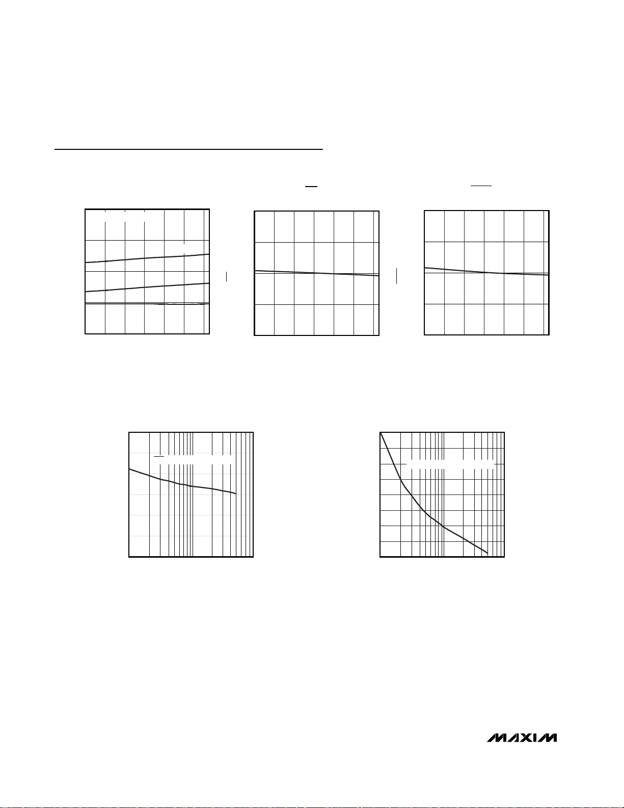
Typical Operating Characteristics
(VDD= 3.6V, VCC= 3.3V, unless otherwise specified. Typical values are at TA= +25°C.)
SUPPLY CURRENT
vs. TEMPERATURE
4
VCC = 3.3V, VDD = 3.6V
3
2
SUPPLY CURRENT (µA)
1
0
-40 80
TEMPERATURE (°C)
MAXIMUM V
TOTAL
I
DD
I
CC
6040200-20
TRANSIENT DURATION
LTH/VHTH
1.10
MAX6846-49 toc01
1.05
1.00
0.95
NORMALIZED LBO TIMEOUT PERIOD
0.90
vs. THRESHOLD OVERDRIVE
120
110
100
90
TRANSIENT DURATION (µs)
HTH
/V
80
LTH
70
MAXIMUM V
60
LBO ASSERTS ABOVE THIS LINE
10 100 1000
THRESHOLD OVERDRIVE (mV)
NORMALIZED LBO TIMEOUT PERIOD
vs. TEMPERATURE
-40 80
TEMPERATURE (°C)
MAX6846-49 toc04
6040200-20
100
90
80
70
60
TRANSIENT DURATION (µs)
50
CC
40
30
MAXIMUM V
20
NORMALIZED RESET TIMEOUT PERIOD
vs. TEMPERATURE
1.100
MAX6846-49 toc02
1.050
1.000
0.950
NORMALIZED RESET TIMEOUT PERIOD
0.900
-40 80
TEMPERATURE (°C)
MAXIMUM VCC TRANSIENT DURATION
vs. THRESHOLD OVERDRIVE
RESET OCCURS ABOVE THIS LINE
10 100 1000
THRESHOLD OVERDRIVE (mV)
MAX6846-49 toc03
6040200-20
MAX6846-49 toc05

MAX6846–MAX6849
Low-Power, Adjustable Battery Monitors with
Hysteresis and Integrated µP Reset
_______________________________________________________________________________________ 5
Typical Operating Characteristics (continued)
(VDD= 3.6V, VCC= 3.3V, unless otherwise specified. Typical values are at TA= +25°C.)
NORMALIZED UPPER AND LOWER LBO TRIP
VOLTAGES vs. TEMPERATURE
1.050
1.025
1.000
0.975
NORMALIZED LBO TRIP VOLTAGES
0.950
-40 80
TEMPERATURE (°C)
RESET OUTPUT
vs. SINK CURRENT
140
VCC = 2.1V, VDD = 3.6V
120
100
MAX6846-49 toc06
NORMALIZED RESET THRESHOLD
6040200-20
NORMALIZED RESET THRESHOLD
vs. TEMPERATURE
1.050
1.025
1.000
0.975
0.950
-40 80
TEMPERATURE (°C)
MAX6846-49 toc09
6040200-20
3.50
3.25
120
100
MAX6846-49 toc07
80
60
LBO OUTPUT (mV)
40
20
0
010
RESET OUTPUT
vs. SOURCE CURRENT
VCC = 3.3V, VDD = 3.6V
LBO OUTPUT
vs. SINK CURRENT
VCC = VDD = 3.3V
I
SINK
MAX6846-49 toc08
8642
(mA)
MAX6846-49 toc10
80
60
RESET OUTPUT (mV)
40
20
0
010
I
(mA)
SINK
8642
3.00
RESET OUTPUT (V)
2.75
2.50
03.5
I
(mA)
SOURCE
3.02.52.01.51.00.5

MAX6846–MAX6849
Low-Power, Adjustable Battery Monitors with
Hysteresis and Integrated µP Reset
6 _______________________________________________________________________________________
Detailed Description
The MAX6846–MAX6849 family is available with several
monitoring options. The MAX6846/MAX6847 have single
low-battery outputs and the MAX6848/MAX6849 have
dual low-battery outputs (see Figures 1a and 1b).
The MAX6846–MAX6849 combine a 615mV reference
with two comparators, logic, and timing circuitry to provide the user with information about the charge state of
the power-supply batteries. The MAX6848/MAX6849
monitor separate high-voltage and low-voltage thresholds to determine battery status. The output(s) can be
used to signal when the battery is charged, when the
battery is low, and when the battery is empty. User-
adjustable thresholds are ideal for monitoring singlecell Li+ or multicell alkaline/NiCd/NiMH power supplies.
When the power-supply voltage drops below the specified low threshold, the low-battery output asserts. When
the voltage rises above the specified high threshold following a 150ms (min) timeout period, the low-battery
output is deasserted. This ensures the supply voltage
has stabilized before power-converter or microprocessor activity is enabled.
These devices also have an independent µP supervisor
that monitors VCCand provides an active-low reset output. A manual reset function is available to allow the
user to reset the µP with a pushbutton.
Pin Description
PIN
MAX6846/MAX6847 MAX6848/MAX6849
11V
2 2 GND Ground
3 3 LTHIN
4 — LBO
55RESET
NAME FUNCTION
6 — MR
7 7 HTHIN
88V
— 6 LBOH
VDD Supply. Device power supply if VDD is greater than VCC.
DD
LTH Threshold Monitor Input. A resistor-divider network sets the low
threshold associated with LBOL and LBO.
Low-Battery Output, Active-Low, Open-Drain. LBO is asserted when LTHIN
drops below the V
above the V
Reset Output, Active-Low, Push-Pull, or Open-Drain. RESET goes from high
to low when the V
remains low for the V
threshold. RESET is one-shot edge-trigger pulsed low for the MR reset
timeout period when the MR input is pulled low. RESET is an open-drain
output for the MAX6846/MAX6848, and a push-pull output for the
MAX6847/MAX6849. The push-pull outputs are referenced to V
is guaranteed to be in the correct logic state for V
Manual Reset Input, Active-Low, Internal 1.5kΩ Pullup to V
to assert a one-shot reset output pulse for the MR reset timeout period.
Leave unconnected or connect to V
debounced for MR rising edges to prevent false reset events.
HTH Threshold Monitor Input. A resistor-divider network sets the high
threshold associated with LBOH and LBO.
VCC Voltage Input. Input for VCC reset threshold monitor and device power
CC
supply if V
Low-Battery Output High, Active-Low, Open-Drain. LBOH is asserted when
HTHIN drops below the V
HTHIN rises above the V
HTH
is greater than VDD.
CC
specification and remains asserted until HTHIN rises
LTH
specification for at least 150ms.
input drops below the selected reset threshold and
CC
reset timeout period after VCC exceeds the reset
CC
or VCC ≥ 10V.
DD
CC
if unused. The MR input is
CC
specification. LBOH is deasserted when
HTH-
specification for at least 150ms.
HTH+
. RESET
CC
. Pull MR low
Low-Battery Output Low, Active-Low, Open-Drain. LBOL is asserted when
— 4 LBOL
LTHIN drops below the V
LTHIN rises above the V
specification. LBOL is deasserted when
LTH-
specification for at least 150ms.
LTH+

MAX6846–MAX6849
Low-Power, Adjustable Battery Monitors with
Hysteresis and Integrated µP Reset
_______________________________________________________________________________________ 7
Figure 1b. MAX6848 Functional Diagram
Figure 1a. MAX6847 Functional Diagram
Low-Battery Output
The low-battery outputs are available in active-low
(LBO, LBOL, LBOH), open-drain configurations. The
low-battery outputs can be pulled to a voltage independent of VCCor VDD, up to 5.5V. This allows the device
to monitor and operate from direct battery voltage while
interfacing to higher voltage microprocessors.
The MAX6846/MAX6847 single-output voltage monitors
provide a single low-battery output, LBO. LBO asserts
when LTHIN drops below V
LTH
and remains asserted
for at least 150ms after HTHIN rises above V
HTH
(see
Figure 2). The MAX6848/MAX6849 dual-output voltage
monitors provide two low-battery outputs: LBOH and
LBOL. LBOH asserts when HTHIN drops below V
HTH-
and remains asserted for at least 150ms after HTHIN
rises above V
HTH+
. LBOL asserts when LTHIN drops
below V
LTH-
and remains asserted for at least 150ms
after LTHIN rises above V
LTH+
(see Figure 3). For fast-
rising V
DD
input, the LBOL timeout period must com-
plete before the LBOH timeout period begins.
Reset Output
The MAX6846–MAX6849 provide an active-low reset
output (RESET). RESET is asserted when the voltage at
V
CC
falls below the reset threshold level. Reset remains
asserted for the reset timeout period after VCCexceeds
the threshold. If VCCgoes below the reset threshold
before the reset timeout period is completed, the internal timer restarts (see Figure 4). The MAX6846/
MAX6848 have open-drain reset outputs, while the
MAX6847/MAX6849 have push-pull reset outputs.
V
LTHIN
HTHIN
V
DD
LTH
DETECT
HTH
DETECT
615mV
CC
LBO TIMEOUT
PERIOD
MAX6847
RSQ
Q
LBO
V
CC
V
LTHIN
HTHIN
V
DD
LTH
DETECT
5%
HYST
HTH
DETECT
5%
HYST
CC
615mV
MAX6848
LBO
TIMEOUT
PERIOD
LBOL
LBOH
RESET
TIMEOUT
PERIOD
RESET
V
CC
MR
1.23V
V
TH
DETECT
RESET
1.23V
V
TH
DETECT
RESET
TIMEOUT
PERIOD

MAX6846–MAX6849
Low-Power, Adjustable Battery Monitors with
Hysteresis and Integrated µP Reset
8 _______________________________________________________________________________________
Figure 2. Single Low-Battery Output Timing
Figure 4.
RESET
Timing Diagram
Figure 3. Dual Low-Battery Output Timing
V
V
TRIPHIGH
V
TRIPLOW
HTH
LTH
MONITORED
LTHIN = 615mV
HTHIN = 615mV
V
HYST
t
LBOP
V
HYST
LBO
= HYSTERESIS
V
(V
TRIPHIGH
V
TRIPHIGH
(V
TRIPLOW
V
TRIPLOW
V
HYST
HTH+
+5%)
HTH-
+5%)
LTH +
LTH -
= HYSTERESIS
LBOL
LBOH
MONITORED
t
LBOP
LTHIN = 615mV
LTHIN = 582mV
t
LBOP
t
LBOD
t
LBOD
HTHIN = 615mV
HTHIN = 582mV
t
LBOD
t
LBOP
t
t
LBOP
LBOP
V
V
HYST
HYST
= 5%
= 5%
V
CC
GND
MR
GND
RESET t
GND
V
TH
SWITCH
BOUNCE
t
MPW
t
MRP
RP
SWITCH
BOUNCE
SWITCH
BOUNCE
t
MRP
t
DEB
t
MPW
SWITCH
BOUNCE
t
DEB

Manual Reset
Many microprocessor-based products require manual
reset capability, allowing the operator, a test technician,
or external logic circuitry to initiate a reset while the
monitored supplies remain above their reset thresholds.
These devices have a dedicated active-low MR pin.
When MR is pulled low, RESET asserts a one-shot low
pulse for the MR reset timeout period. The MR input has
an internal 1.5kΩ pullup resistor to VCCand can be left
unconnected if not used. MR can be driven with CMOSlogic levels, open-drain/open-collector outputs, or a
momentary pushbutton switch to GND (the MR function
is internally debounced for the t
DEB
timeout period) to
create a manual reset function. If MR is driven from long
cables, or if the device is used in a noisy environment,
connect a 0.1µF capacitor from MR to GND to provide
additional noise immunity (see Figure 4).
Hysteresis
Hysteresis increases the comparator’s noise margin by
increasing the upper threshold or decreasing the lower
threshold. The hysteresis prevents the output from
oscillating (chattering) when monitor input is near the
low-battery threshold. This is especially important for
applications where the load on the battery creates significant fluctuations in battery voltages (see Figures 2
and 3).
For the MAX6846/MAX6847, hysteresis is set using three
external resistors (see Figure 5). The MAX6848/MAX6849
have dual, low-battery input levels. Each input level has a
5% (typ) hysteresis.
Applications Information
Resistor-Value Selection (Programming
the Adjustable Thresholds)
MAX6846/MAX6847
Use the following steps to determine values for R1, R2,
and R3 of Figure 5.
1) Choose a value for R
TOTAL
, the sum of R1, R2, and
R3. Because the MAX6846/MAX6847 have very high
input impedance, R
TOTAL
can be up to 500kΩ.
2) Calculate R3 based on R
TOTAL
and the desired
upper trip point:
3) Calculate R2 based on R
TOTAL
, R3, and the desired
lower trip point:
4) Calculate R1 based on R
TOTAL
, R3, and R2:
MAX6848/MAX6849
V
LTH-
= V
HTH-
= 582mV
LBOL low-trip level:
LBOH low-trip level:
Use the following steps to determine values for R1, R2,
and R3 of Figure 5.
MAX6846–MAX6849
Low-Power, Adjustable Battery Monitors with
Hysteresis and Integrated µP Reset
_______________________________________________________________________________________ 9
Figure 5. Adjustable Threshold Selection
V
DD
R1
R2
R3
R
V
DD
LTHIN
HTHIN GND
3
615
615
mV R
V
TRIPLOW
R
2
MAX6846
MAX6847
MAX6848
MAX6849
* FOR THE MAX6846/MAX6847.
( ) FOR THE MAX6848/MAX6849.
mV R
=×
V
TRIPHIGH
×
TOTAL
LBO*
(LBOH)
(LBOL)
TOTAL
-
3
=
R
VV mV
==
LTH HTH
VV
TRIPLOW LTH
VV
TRIPHIGH HTH
=×
=×
RRRR
TOTAL
=++
615
12 3
RR R
++
23
RR
123
++
RRR
R
+
3
12 3
RR RR
123 = --
TOTAL
RR R
VV
TRIPLOW LTH
=×
-
12 3
++
RR
23
+
RR R
++
12 3
VV
TRIPHIGH HTH
RRRR
TOTAL
=×
=++
12 3
-
R
3

MAX6846–MAX6849
Low-Power, Adjustable Battery Monitors with
Hysteresis and Integrated µP Reset
10 ______________________________________________________________________________________
1) Choose a value for R
TOTAL
, the sum of R1, R2, and
R3. Because the MAX6848/MAX6849 have very high
input impedance, R
TOTAL
can be up to 500kΩ.
2) Calculate R3 based on R
TOTAL
and the desired
upper trip point:
3) Calculate R2 based on R
TOTAL
, R3, and the desired
lower trip point:
4) Calculate R1 based on R
TOTAL
, R3, and R2:
5) LBOL high-trip level:
V
TRIPLOW
✕ 1.05
6) LBOH high-trip level:
V
TRIPHIGH
✕ 1.05
Monitoring Multicell Battery Applications
For monitoring multicell Li+ (or a higher number of alkaline/NiCd/NiMH cells), connect VDDto a supply voltage
between 1.6V to 5.5V. Figure 6 shows VDDconnected
directly to V
CC.
To calculate the values of R1, R2, and
R3, see the Resistor-Value Selection section.
DC-DC Converter Application
The MAX6848/MAX6849 dual battery monitors can be
used in conjunction with a DC-DC converter to power
microprocessor systems using a single Li+ cell or two
to three alkaline/NiCd/NiMH cells. The LBOH output
indicates that the battery voltage is weak, and is used
to warn the microprocessor of potential problems.
Armed with this information, the microprocessor can
reduce system power consumption. The LBOL output
indicates the battery is empty and system power should
be disabled. By connecting LBOL to the SHDN pin of the
DC-DC converter, power to the microprocessor is
removed. Microprocessor power does not return until the
battery has recharged to a voltage greater than V
LTH+
(see Figure 7).
Table 1. Factory-Trimmed VCCReset
Threshold Levels
Table 2. VCCReset Timeout Period Suffix
Guide
Figure 7. DC-DC Converter Application
Figure 6. Monitoring Multicell Li+ Applications
R
3
582
mV R
=×
TOTAL
V
TRIPHIGH
mV R
R
582
2
RR RR
123 = --
V
TRIPLOW
TOTAL
×
TOTAL
3
=
R
-
V
MONITORED
R1
LTHIN
R2
HTHIN GND
R3
V
V
DD
CC
MAX6846
MAX6847
MAX6848
MAX6849
* FOR THE MAX6846/MAX6847.
( ) FOR THE MAX6848/MAX6849.
LBO*
(LBOL)
(LBOH)
V
CC
PART NO.
SUFFIX
( _ )
T 3.075
S 2.925
R 2.625
Z 2.313
Y 2.188
W 1.665
V 1.575
THRESHOLD (V)
VCC NOMINAL
RESET
TIMEOUT
PERIOD SUFFIX
D3 150 300
D7 1200 2400
Li+
3.6V
ACTIVE TIMEOUT PERIOD (ms)
MIN MAX
IN
V
DD
LTHIN
HTHIN
MAX6848
MAX6849
OUT
DC-DC
SHDN
LBOL
V
CC
LBOH
RESET
GND GND
NMI
RESET
V
CC
µP

MAX6846–MAX6849
Low-Power, Adjustable Battery Monitors with
Hysteresis and Integrated µP Reset
______________________________________________________________________________________ 11
Selector Guide
Standard Versions Table
DC-DC
MR
V
DD
MAX6846
MAX6847
NMI
RESET
µP
V
CC
Li+
3.6V
RESET
LBO
V
CC
GND GND
LTHIN
HTHIN
Typical Application Circuit
Chip Information
TRANSISTOR COUNT: 1478
PROCESS: BiCMOS
PART
MAX6846 X — X —
MAX6847 — XX—
MAX6848 X —— X
MAX6849 — X — X
PART TOP MARK
MAX6846KARD3 AEJI
MAX6846KASD3 AEJD
MAX6846KAWD3 AEJK
MAX6846KAZD3 AEJJ
MAX6847KARD3 AEJE
MAX6847KASD3 AEJL
MAX6847KAWD3 AEJN
MAX6847KAZD3 AEJM
MAX6848KARD3 AEJP
MAX6848KASD3 AEJO
MAX6848KAWD3 AEJR
MAX6848KAZD3 AEJQ
MAX6849KARD3 AEJT
MAX6849KASD3 AEJS
MAX6849KAWD3 AEJV
MAX6849KAZD3 AEJU
OPEN-DRAIN
RESET
PUSH-PULL RESET
SINGLE LOW-
BATTERY OUTPUT
DUAL LOW-BATTERY
OUTPUT

MAX6846–MAX6849
Low-Power, Adjustable Battery Monitors with
Hysteresis and Integrated µP Reset
Maxim cannot assume responsibility for use of any circuitry other than circuitry entirely embodied in a Maxim product. No circuit patent licenses are
implied. Maxim reserves the right to change the circuitry and specifications without notice at any time.
12 ____________________Maxim Integrated Products, 120 San Gabriel Drive, Sunnyvale, CA 94086 408-737-7600
© 2003 Maxim Integrated Products Printed USA is a registered trademark of Maxim Integrated Products.
Package Information
(The package drawing(s) in this data sheet may not reflect the most current specifications. For the latest package outline information
go to www.maxim-ic.com/packages
.)
b
C
L
C
L
PIN 1
I.D. DOT
(SEE NOTE 6)
e1
D
C
A2
A
L
e
A1
NOTE:
1. ALL DIMENSIONS ARE IN MILLIMETERS.
2. FOOT LENGTH MEASURED FROM LEAD TIP TO UPPER RADIUS OF
HEEL OF THE LEAD PARALLEL TO SEATING PLANE C.
3. PACKAGE OUTLINE EXCLUSIVE OF MOLD FLASH & METAL BURR.
4. PACKAGE OUTLINE INCLUSIVE OF SOLDER PLATING.
5. COPLANARITY 4 MILS. MAX.
6. PIN 1 I.D. DOT IS 0.3 MM MIN. LOCATED ABOVE PIN 1.
7. SOLDER THICKNESS MEASURED AT FLAT SECTION OF LEAD
BETWEEN 0.08mm AND 0.15mm FROM LEAD TIP.
8. MEETS JEDEC MO178.
SEE DETAIL "A"
E
0.25 BSC.
0.65 BSC.
1.95 REF.
0
0
MAX
1.45
0.15
1.30
0.45
0.20
3.00
3.002.60E
1.75
0.60
8
GAUGE PLANE
SOT23, 8L .EPS
SYMBOL
A
C
C
L
E1
L
L2
e
e1
MIN
0.90
0.00A1
0.90A2
0.28b
0.09
2.80D
1.50E1
0.30
0
C
L2
SEATING PLANE C
L
DETAIL "A"
PROPRIETARY INFORMATION
TITLE:
PACKAGE OUTLINE, SOT-23, 8L BODY
REV.DOCUMENT CONTROL NO.APPROVAL
21-0078
1
D
1
 Loading...