

Page 1
________________________________
概述
MAX6695/MAX6696
是两款精密的双远端及本地数字温
度传感器。这两款器件都能精确地测量其管芯的温度以
及两个外部连接为二极管形式的晶体管的温度,并通过
2
线串行接口以数字形式报告温度测量值。远端二极管通
常为
CPU、FPGA、GPU或ASIC
上的共集电极
PNP
管的
发射结。
2
线串行接口可接受标准的系统管理总线
(SMBusTM)
命
令,例如写字节、读字节、发字节及收字节等,并能通
过这些命令来读取温度数据以及对告警门限与转换速率
进行编程。
MAX6695/MAX6696
具有可编程的转换速
率,并且能够以设定好的速率自主运行,便于设计者对
电源电流及温度刷新速率进行控制,以符合系统要求。对
于
2Hz
或更低的温度转换速率,以带符号位的10位二进制
数来表示温度,分辨率为
+0.125°C
。当转换速率为
4Hz
时,
输出数据为带符号位的7位二进制数,分辨率为
+1°C
。
MAX6695/MAX6696
还具有可提高系统可靠性的
SMBus
超时特性。
在
+60°C至+100°C
范围内,无需校准,远端温度测量精
度即可达到±
1.5°C。MAX6695/MAX6696
可测量的温度范
围为
-40°C至+125°C
。除具有
SMBus ALERT
输出外,
MAX6695/MAX6696
还具有两个温度过限指示
(OT1
和
OT2)
,仅当温度高于对应的可编程温度门限时有效。
OT1和OT2
输出通常用于风扇控制、降低时钟频率或系统
关机。
MAX6695
拥有一个固定的
SMBus
地址,而
MAX6696
则
具有九个引脚可选的
SMBus
地址。
MAX6695
采用10引脚
µMAX
®
封装,而
MAX6696
则采用16引脚
QSOP
封装。
这两款器件均可在
-40°C至+125°C
温度范围内工作。
________________________________
应用
笔记本电脑
台式计算机
服务器
工作站
测试与测量设备
________________________________
特性
♦ 测量一路本地或两路远端温度
♦11位、
+0.125°C
分辨率
♦ 高精度:在
+60°C至+100°C (远端)
温度范围内
可达
±1.5°C (最大)
♦
ACPI
兼容
♦ 可编程高/低温告警
♦ 可编程转换速率
♦ 三种告警输出:
ALERT、OT1及OT2
♦
SMBus/I2C
兼容接口
♦ 兼容于
65nm
处理工艺(Y版
)
MAX6695/MAX6696
双路远端/本地温度传感器,
带
SMBus
串行接口
________________________________________________________________ Maxim Integrated Products 1
____________________________
定购信息
_________________________
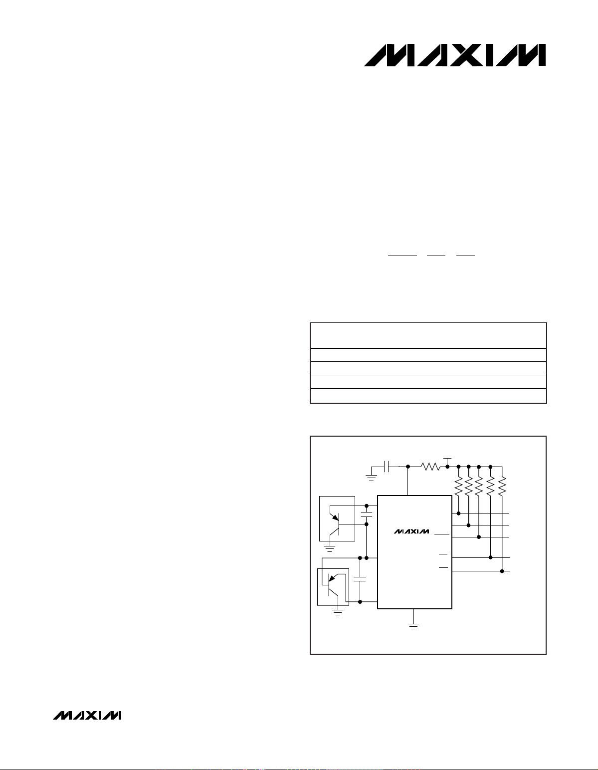
典型工作电路
19-3183; Rev 2; 11/05
本文是Maxim 正式英文资料的译文,Maxim不对翻译中存在的差异或由此产生的错误负责。请注意译文中可能存在文字组织或
翻译错误,如需确认任何词语的准确性,请参考 Maxim提供的英文版资料。
索取免费样品和最新版的数据资料,请访问Maxim的主页:www.maxim-ic.com.cn。
SMBus是Intel Corp.
的商标。
引脚配置在数据资料的最后给出。
CLOCK
DATA
TO SYSTEM
SHUTDOWN
GND
OT2
SMBCLK
OT1
SMBDATA
V
CC
INTERRUPT
TO µP
0.1µF
DXN
DXP1
47Ω
10kΩ
EACH
ALERT
+3.3V
CPU
TO CLOCK
THROTTLING
DXP2
GRAPHICS
PROCESSOR
MAX6695
典型工作电路(续)在数据资料的最后给出。
µMAX是Maxim Integrated Products, Inc.
的注册商标。
PART TEMP RANGE
MAX6695AUB -40°C to +125°C
MAX6695YAUB -40°C to +125°C
MAX6696AEE -40°C to +125°C
MAX6696YAEE -40°C to +125°C
PINPACKAGE
10 µMAX
10 µMAX
16 QSOP
16 QSOP
CODE
U10C-4
U10C-4
E16-1
E16-1
PKG
Page 2

MAX6695/MAX6696
双路远端/本地温度传感器,
带
SMBus
串行接口
2 _______________________________________________________________________________________
ABSOLUTE MAXIMUM RATINGS
Stresses beyond those listed under “Absolute Maximum Ratings” may cause permanent damage to the device. These are stress ratings only, and functional
operation of the device at these or any other conditions beyond those indicated in the operational sections of the specifications is not implied. Exposure to
absolute maximum rating conditions for extended periods may affect device reliability.
VCC...........................................................................-0.3V to +6V
DXP1, DXP2................................................-0.3V to (V
CC
+ 0.3V)
DXN ......................................................................-0.3V to +0.8V
SMBCLK, SMBDATA, ALERT ...................................-0.3V to +6V
RESET, STBY, ADD0, ADD1, OT1, OT2 ...................-0.3V to +6V
SMBDATA Current .................................................1mA to 50mA
DXN Current ......................................................................±1mA
Continuous Power Dissipation (T
A
= +70°C)
10-Pin µMAX (derate 6.9mW/°C above +70°C) ........555.6mW
16-Pin QSOP (derate 8.3mW/°C above +70°C) .......666.7mW
Operating Temperature Range .........................-40°C to +125°C
Junction Temperature .....................................................+150°C
Storage Temperature Range ............................-65°C to +150°C
Lead Temperature (soldering, 10s) ................................+300°C
ELECTRICAL CHARACTERISTICS
(VCC= +3.0V to +3.6V, TA= 0°C to +125°C, unless otherwise noted. Typical values are at VCC= +3.3V and TA= +25°C)
Supply Voltage V
Standby Supply Current SMBus static, ADC in idle state 10 µA
Operating Current Interface inactive, ADC active 0.5 1 mA
Remote Temperature Error
(Note 1)
Local Temperature Error
Local Temperature Error
(MAX6695Y/MAX6696Y)
Power-On Reset Threshold VCC, falling edge (Note 2) 1.3 1.45 1.6 V
POR Threshold Hysteresis 500 mV
Undervoltage Lockout Threshold UVLO Falling edge of VCC disables ADC 2.2 2.8 2.95 V
Undervoltage Lockout Hysteresis 90 mV
Conversion Time
Remote-Diode Source Current I
PARAMETER SYMBOL CONDITIONS MIN TYP MAX UNITS
CC
Conversion rate = 0.125Hz 35 70
Conversion rate = 1Hz 250 500Average Operating Current
Conversion rate = 4Hz 500 1000
TRJ = +25°C to +100°C
(T
= +45°C to +85°C)
A
T
= 0° C to + 125° C ( TA = + 25° C to + 100° C ) -3.0 +3.0
R J
TRJ = -40°C to +125°C (TA = 0°C to +125°C) -5.0 +5.0
T
= -40°C to +125°C (TA = -40°C) +3.0
RJ
TA = +45°C to +85°C -2.0 +2.0
TA = +25°C to +100°C -3.0 +3.0
TA = 0°C to +125°C -4.5 +4.5
= -40°C to +125°C +3.0
T
A
TA = +45°C to +85°C -3.8
TA = +25°C to +100°C -4.0
TA = 0°C to +125°C -4.2
T
= -40°C to +125°C -4.4
A
Channel 1 rate ≤4Hz, channel 2 / local rate
≤2Hz (conversion rate register ≤05h)
Channel 1 rate ≥8Hz, channel 2 / local rate
≥4Hz (conversion rate register ≥06h)
High level 80 100 120
RJ
Low level 8 10 12
3.0 3.6 V
-1.5 +1.5
112.5 125 137.5
56.25 62.5 68.75
µA
°C
°C
°C
ms
µA
Page 3

MAX6695/MAX6696
双路远端/本地温度传感器,
带
SMBus
串行接口
_______________________________________________________________________________________ 3
ELECTRICAL CHARACTERISTICS (continued)
(VCC= +3.0V to +3.6V, TA= 0°C to +125°C, unless otherwise noted. Typical values are at V
CC
= +3.3V and TA= +25°C)
Note 1: Based on diode ideality factor of 1.008.
Note 2: Specifications are guaranteed by design, not production tested.
PARAMETER SYMBOL CONDITIONS MIN TYP MAX UNITS
ALERT, OT1, OT2
Output Low Sink Current VOL = 0.4V 6 mA
Output High Leakage Current VOH = 3.6V 1 µA
INPUT PIN, ADD0, ADD1 (MAX6696)
Logic Input Low Voltage V
Logic Input High Voltage V
INPUT PIN, RESET, STBY (MAX6696)
Logic Input Low Voltage V
Logic Input High Voltage V
Input Leakage Current I
SMBus INTERFACE (SMBCLK, SMBDATA, STBY)
Logic Input Low Voltage V
Logic Input High Voltage V
Input Leakage Current I
Output Low Sink Current I
Input Capacitance C
SMBus-COMPATIBLE TIMING (Figures 4 and 5) (Note 2)
Serial Clock Frequency f
Bus Free Time Between STOP
and START Condition
Repeat START Condition Setup
Time
START Condition Hold Time t
STOP Condition Setup Time t
Clock Low Period t
Clock High Period t
Data Setup Time t
Data Hold Time t
SMB Rise Time t
SMB Fall Time t
SMBus Timeout SMBDATA low period for interface reset 20 30 40 ms
IL
IH
IL
IH
LEAK
IL
IH
LEAK
OL
IN
SCL
t
BUF
t
SU:STA
HD:STA
SU:STO
LOW
HIGH
SU:DAT
HD:DAT
R
F
VIN = GND or V
VOL = 0.6V 6 mA
90% of SMBCLK to 90% of SMBDATA 4.7 µs
10% of SMBDATA to 90% of SMBCLK 4 µs
90% of SMBCLK to 90% of SMBDATA 4 µs
10% to 10% 4 µs
90% to 90% 4.7 µs
CC
2.9 V
2.1 V
-1 +1 µA
2.1 V
5pF
10 100 kHz
4.7 µs
250 µs
300 µs
0.3 V
0.8 V
0.8 V
±1 µA
1µs
300 ns
Page 4
MAX6695/MAX6696
双路远端/本地温度传感器,
带
SMBus
串行接口
4 _______________________________________________________________________________________
________________________________________________________________
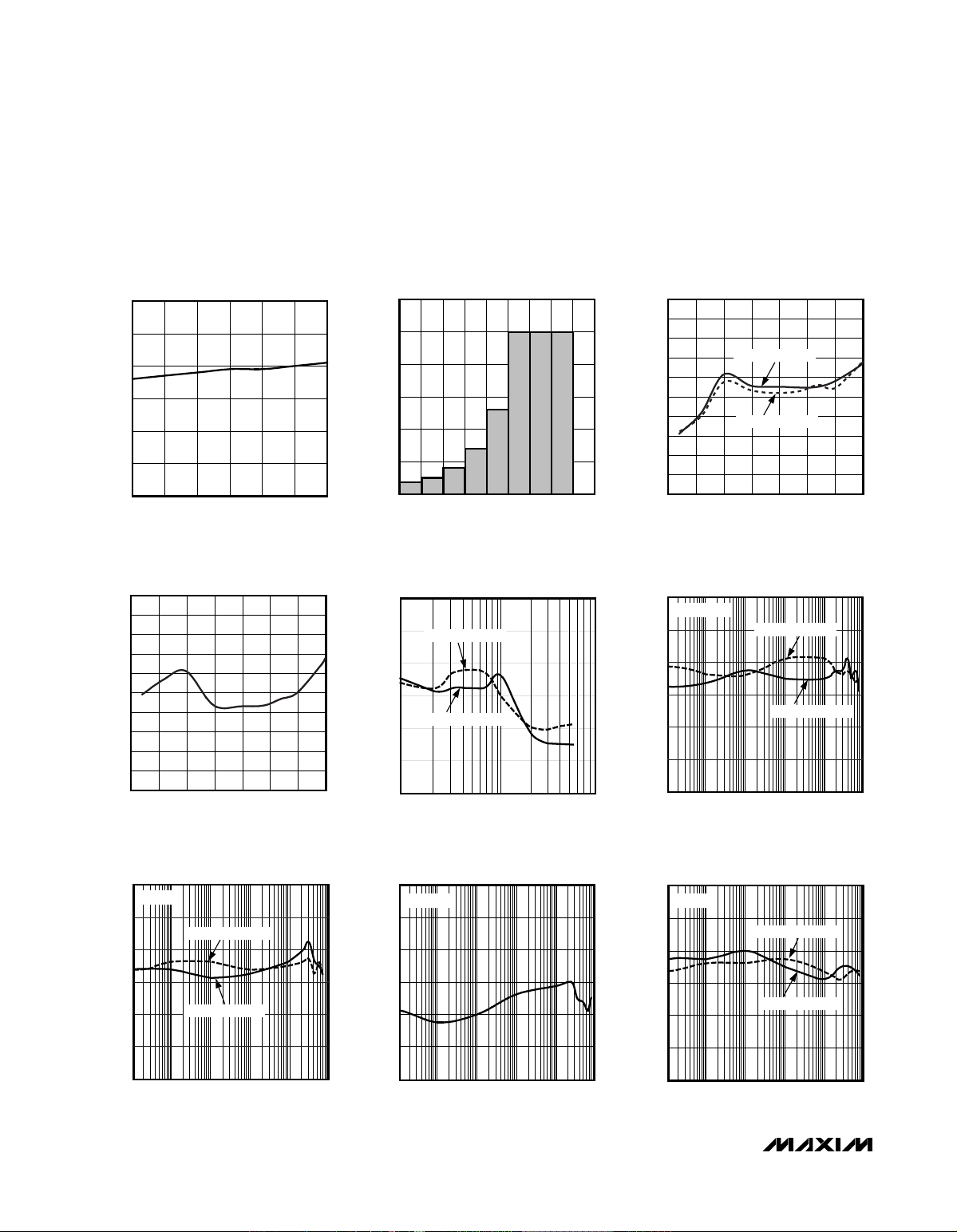
典型工作特性
(VCC= 3.3V, TA= +25°C, unless otherwise noted.)
STANDBY SUPPLY CURRENT
vs. SUPPLY VOLTAGE
MAX6695 toc01
SUPPLY VOLTAGE (V)
STANDBY SUPPLY CURRENT (µA)
3.53.43.33.23.1
1
2
3
4
5
6
0
3.0 3.6
AVERAGE OPERATING SUPPLY CURRENT
vs. CONVERSION RATE CONTROL REGISTER VALUE
MAX6695 toc02
CONVERSION RATE CONTROL REGISTER VALUE (hex)
OPERATING SUPPLY CURRENT (µA)
321
100
200
300
400
500
600
0
07654
TEMPERATURE ERROR
vs. REMOTE-DIODE TEMPERATURE
MAX6695 toc03
REMOTE TEMPERATURE (°C)
TEMPERATURE ERROR (°C)
1007525 500-25
-4
-3
-2
-1
0
1
2
3
4
5
-5
-50 125
REMOTE CHANNEL2
REMOTE CHANNEL1
LOCAL TEMPERATURE ERROR
vs. DIE TEMPERATURE
MAX6695 toc04
DIE TEMPERATURE (°C)
TEMPERATURE ERROR (°C)
1007525 500-25
-4
-3
-2
-1
0
1
2
3
4
5
-5
-50 125
TEMPERATURE ERROR
vs. DXP-DXN CAPACITANCE
MAX6695 toc05
DXP-DXN CAPACITANCE (nF)
TEMPERATURE ERROR (°C)
3
-3
-2
-1
0
1
2
1 10 100
REMOTE CHANNEL1
REMOTE CHANNEL2
3
0.001 0.01 0.1 1 10 100
2
1
0
-1
-2
-3
TEMPERATURE ERROR
vs. DIFFERENTIAL NOISE FREQUENCY
MAX6695 toc06
FREQUENCY (MHz)
TEMPERATURE ERROR (°C)
REMOTE CHANNEL1
VIN = 10mV
P-P
REMOTE CHANNEL2
3
0.001 0.01 0.1 1 10 100
2
1
0
-2
-1
-3
REMOTE TEMPERATURE ERROR
vs. POWER-SUPPLY NOISE FREQUENCY
MAX6695 toc07a
FREQUENCY (MHz)
TEMPERATURE ERROR (°C)
100mV
P-P
REMOTE CHANNEL2
REMOTE CHANNEL1
3
0.001 0.01 0.1 1 10 100
2
1
-1
0
-2
-3
LOCAL TEMPERATURE ERROR
vs. POWER-SUPPLY NOISE FREQUENCY
MAX6695 toc07b
FREQUENCY (MHz)
TEMPERATURE ERROR (°C)
100mV
P-P
3
0.001 0.01 0.1 1 10 100
2
1
0
-1
-2
-3
TEMPERATURE ERROR
vs. COMMON-MODE NOISE FREQUENCY
MAX6695 toc08
FREQUENCY (Hz)
TEMPERATURE ERROR (°C)
REMOTE CHANNEL1
10mV
P-P
REMOTE CHANNEL2
Page 5

MAX6695/MAX6696
双路远端/本地温度传感器,
带
SMBus
串行接口
_______________________________________________________________________________________ 5
___________________________________________________________________
引脚说明
引脚
名称
功能
电源电压输入,
+3V至+3.6V
。用一个
0.1µF
电容旁路至地。建议使用一个
47Ω
串联电阻,但无需进行额外的噪声滤波。参见
典型工作电路
部分。
远端二极管通道1激励电流输出与
A/D
正输入组合引脚。不要浮空
DXP1
,
如果不使用远端二极管则将
DXP1
连接至
DXN。在DXP1与DXN
之间连接
一个
2200pF
电容用于滤波。
远端二极管激励电流返回与
A/D
负输入组合引脚。
DXN
在内部被偏置为高于
地电位的一个二极管压降。
远端二极管通道2激励电流输出与
A/D
正输入组合引脚。不要浮空
DXP2
,
如果不使用远端二极管则将
DXP2
连接至
DXN
。在DXP2 与
DXN
之间连接
一个
2200pF
电容用于滤波。
低有效温度越限告警输出,漏极开路。仅当温度超过编程设定的
OT1
门限时,
OT1
才为低。
接地。
SMBus
串行时钟输入。
SMBus
串行数据输入/输出,漏极开路。
无连接。
SMBus从地址选择输入(表10)。
ADD0及ADD1
在上电时被采样。
复位输入。
RESET
为高时将所有寄存器设置为默认值(上电复位状态)。
RESET
为低时正常工作。
SMBus
从地址选择输入(表10)。
ADD0及ADD1
在上电时被采样。
硬件待机控制输入。拉低
STBY
使器件进入待机模式,并保留所有寄存器中的数据。
低有效温度越限告警输出,漏极开路。仅当温度超过编程设定的
OT2
门限时,
OT2
才为低。
SMBus
告警(中断),低有效漏极开路输出。当温度超过用户设置门限(高温或
低温),或某个远端传感器开路时触发报警。报警后将一直保持为低,直至读取
状态寄存器或成功响应了告警响应地址为止。参见
ALERT中断模式
部分。
PIN
MAX6695 MAX6696
12V
2 3 DXP1
3 4 DXN
4 5 DXP2
510OT1
6 8 GND Ground
7 9 SMBCLK SMBus Serial-Clock Input
811ALERT
9 12 SMBDATA SMBus Serial-Data Input/Output, Open Drain
10 13 OT2
— 1, 16 N.C. No Connect
— 6 ADD1
— 7 RESET
— 14 ADD0
—15STBY
NAME FUNCTION
Supply Voltage Input, +3V to +3.6V. Bypass to GND with a 0.1µF capacitor. A
CC
47Ω series resistor is recommended but not required for additional noise
filtering. See Typical Operating Circuit.
Combined Remote-Diode Current Source and A/D Positive Input for Remote-
Diode Channel 1. DO NOT LEAVE DXP1 FLOATING; connect DXP1 to DXN if no
remote diode is used. Place a 2200pF capacitor between DXP1 and DXN for
noise filtering.
Combined Remote-Diode Current Sink and A/D Negative Input. DXN is internally
biased to one diode drop above ground.
Combined Remote-Diode Current Source and A/D Positive Input for Remote-
Diode Channel 2. DO NOT LEAVE DXP2 FLOATING; connect DXP2 to DXN if no
remote diode is used. Place a 2200pF capacitor between DXP2 and DXN for
noise filtering.
Overtemperature Active-Low Output, Open Drain. OT1 is asserted low only when
the temperature is above the programmed OT1 threshold.
SMBus Alert (Interrupt) Active-Low Output, Open-Drain. Asserts when
temperature exceeds user-set limits (high or low temperature) or when a remote
sensor opens. Stays asserted until acknowledged by either reading the status
register or by successfully responding to an alert response address. See the
ALERT Interrupts section.
Overtemperature Active-Low Output, Open Drain. OT2 is asserted low only when
temperature is above the programmed OT2 threshold.
SMBus Slave Address Select Input (Table 10). ADD0 and ADD1 are sampled
upon power-up.
Reset Input. Drive RESET high to set all registers to their default values (POR
state). Pull RESET low for normal operation.
SMBus Slave Address Select Input (Table 10). ADD0 and ADD1 are sampled
upon power-up.
Hardware Standby Input. Pull STBY low to put the device into standby mode.
All registers’ data are maintained.
Page 6

MAX6695/MAX6696
____________________________
详细说明
MAX6695/MAX6696
是两款设计用来与微处理器或其他
智能器件协同工作的温度监视、保护及控制器件。其他
器件可通过
SMBus
串行接口及专用告警引脚与
MAX6695/
MAX6696
通信。当温度超过软件编程设定的温度告警门
限时,发出高温告警信号
OT1及OT2。OT1及OT2
可与风
扇、系统关机及其他温控电路连接。
MAX6695/MAX6696
能够以编程设定好的速率连续将温
度转换为数字数据,或者也可选择单次转换模式。在最高
转换速率下,温度转换结果保存在“主”温度数据寄存器内
(
地址为
00h及01h)
,格式为7位+符号,
LSB
等于
+1°C
。
在较低转换速率下,在地址
11h及10h
上额外再加上3位来
提供
+0.125°C
的温度分辨率。数据格式参见表2、3及4。
ADC
及多路复用器
MAX6695/MAX6696均值ADC (图1)在62.5ms或125ms
的
周期内作积分(每个通道,典型值),具体数字取决于转换
速率(参见
Electrical Characteristics
表格)。均值
ADC
可提
供优异的噪声抑制能力。
MAX6695/MAX6696
内的多路复用器(图1)自动引导偏置
电流流入远端及本地二极管。
ADC
及相关电路测量每一
个二极管的正向电压并根据这些电压来计算温度。如果
某个远端通道没有使用,则将
DXP_
连接至
DXN
。请注意
不要使
DXP_与DXN
开路。当启动转换时,不管使用还是
不使用,所有通道都会被转换。
DXN
输入由一个内部二
极管偏置成高于地电位的一个
V
BE
,以便于
ADC
进行差
分测量。与远端二极管串联的电阻会引起大约每欧姆
+1/2°C
的误差。
A/D
转换序列
一次转换序列由一次本地温度测量及两次远端温度测量
组成。每次启动转换,无论是以自动转换模式
(RUN /
STOP = 0)
来自动启动,还是通过写入一条单触发命令来
启动,全部三个通道都将被转换,且三个测量结果都在
转换结束后可用。由于通常要求一个远端通道的温度测
量比其他两个通道的温度测量速度快一些,因此转换序
列被设计成远端1、本地、远端1、远端2,因此远端1通
道的转换速率为其他两个通道转换速率的两倍。
状态寄存器中的
BUSY
状态位(参见表7及
状态字节功能
部
分)表示器件正在进行一次新的转换。当
ADC
忙时,以前
的转换结果总是有效的。
远端二极管的选择
MAX6695/MAX6696
可直接测量
CPU
或其他具有片上感
温二极管(参见
典型工作电路
)的IC
的温度,或测量连接成
二极管形式的分立晶体管的温度。
理想因子
远端温度测量的精度取决于远端“二极管”(实际上是一
个晶体管)的理想因子
(n)。MAX6695/MAX6696 (
并非
MAX6695Y/MAX6696Y)
已经对
n = 1.008
进行了优化。
IC
衬底上的热敏二极管通常为一个集电极接地的
PNP
晶体
管。
DXP_
必须与阳极(射极)连接,而
DXN
则必须与阴极
(
基极)连接。
如果使用理想因子不等于
1.008
的温度检测晶体管,则输
出数据将与使用最佳理想因子检测晶体管所得到的数据
有一定的差别。但幸运的是,这种差别可以预测。假设
用标称理想因子
n
NOMINAL
的远端二极管传感器来测量具
有不同理想因子
n
1
的二极管的温度,则可按下式来校正
所测温度
T
M
:
其中温度以开尔文表示,且
MAX6695/MAX6696
的
n
NOMIMAL
等于
1.008
。
例如,假设您想用
MAX6695或MAX6696
来测量一个理
想因子为
1.002的CPU
,如果二极管没有串联电阻,则与
实际温度有关的测量数据如下:
对于
+85°C (358.15K)
的实际温度,所测温度为
+82.87°C
(356.02K)
,误差为
-2.13°C
。
串联电阻
温度检测二极管的串联电阻
(R
S
)
可引起额外的误差。对于
10µA及100µA
的额定二极管电流,串联电阻所引起的电
TT
n
n
TT
ACTUAL M
NOMINAL
MM
=×
⎛
⎝
⎜
⎞
⎠
⎟
=×
⎛
⎝
⎜
⎞
⎠
⎟
=×
()
1
1 008
1 002
1 00599
.
.
.
TT
n
n
M ACTUAL
NOMINAL
=×
⎛
⎝
⎜
⎞
⎠
⎟
1
双路远端/本地温度传感器,
带
SMBus
串行接口
6 _______________________________________________________________________________________
Page 7

压测量误差为:
由于
1°C
对应
198.6µ V
,故由串联电阻引起的温度偏
差为:
假设被测二极管具有3Ω的串联电阻,则由串联电阻引起
的温度偏差为:
由理想因子及串联电阻所引起的结果是相加的。如果二
极管带有
1.002
的理想因子及3Ω的串联电阻,则总的偏差
量等于串联电阻误差+理想因子误差:
1.36°C - 2.13°C = -0.77°C
二极管温度为
+85°C
。
3 0 453 1 36ΩΩ×
°
=+ °. .
C
C
90
198 6
0 453
µµV
V
C
C
Ω
Ω
.
.°=
°
∆VAARAR
MSS
=−×=×()100 10 90µµ µ
MAX6695/MAX6696
双路远端/本地温度传感器,
带
SMBus
串行接口
_______________________________________________________________________________________ 7
图
1. MAX6695/MAX6696
功能框图
DXP1
DXN
DXP2
ALERT
OT1
OT2
V
CC
RESET/
UVLO
CIRCUITRY
(RESET)
Q
Q
Q
3
MUX
REMOTE1
REMOTE2
LOCAL
DIODE FAULT
S
R
REMOTE TEMPERATURES
S
R
S
R
LOCAL TEMPERATURES
ALERT RESPONSE ADDRESS
() ARE FOR MAX6696 ONLY.
ADC
REGISTER BANK
COMMAND BYTE
ALERT THRESHOLD
OT1 THRESHOLDS
OT2 THRESHOLDS
CONTROL
LOGIC
SMBus
8
READ
8
WRITE
7
ADDRESS
DECODER
(STBY)
SMBDATA
SMBCLK
(ADD0)
(ADD1)
Page 8

MAX6695/MAX6696
在此例中,由串联电阻及理想因子所产生的误差部分相
抵消。
分立远端二极管
当远端二极管为分立晶体管时,其集电极与基极必须连
在一起。表1列出了一些适合与
MAX6695/MAX6696
一起
使用的分立晶体管的例子。
晶体管必须为正向电压相对较高的小信号晶体管,否则
可能会超出
A/D
的输入电压范围。最高预计温度下的正向
电压必须在
10µA
电流时大于
0.25V
;而最低预计温度下
的正向电压必须在
100µA
电流时小于
0.95V
。不要使用大
功率晶体管。此外,还应保证基区电阻小于
100Ω
。正向
电流增益的严格规范(例如
50 < ß <150)
表明制造商拥有良
好的工艺控制技术,器件拥有一致的
V
BE
特性。
分立晶体管厂商通常不规定或保证理想因子。由于质量
好的分立晶体管一般都拥有范围相对较窄的理想因子,
因此这通常不会成为一个问题。我们已经注意到:使用
分立晶体管时,远端温度的读数变化小于
±2°C
。而且,
设计时应以备选厂家提供的数种分立晶体管来检验温度
读数是否具有良好的一致性。
热量及自热
在检测本地温度时,这些温度传感器一般测量其所在
PC
板的温度。引线在PC板连线与芯片之间提供了一个良好
的热通道。和所有其它的IC温度传感器一样,芯片和环
境空气之间的导热能力相对较差,因此用它来测量环境
气温不太现实。由于PC板发出的热量远大于
MAX6695/
MAX6696
自身的热量,故器件温度变化几乎完全与PC板
的温度变化一致。
当用片内温度检测结来测量
CPU
或其他IC温度时,热量
其实没有多大的影响;被测结温跟踪转换周期内的实际
温度。当用分立远端晶体管来测量温度时,采用小封装
(
亦即
SOT23或SC70)
晶体管可获得最佳的热响应速度。
应仔细计算热源与传感器之间的温度梯度,且需保证穿
过传感器封装的气流不至于影响其温度测量精度。
传感器自热不会明显影响温度测量精度。由二极管电流
源引起的远端传感器自热可忽略不计。对于本地温度测
量,当以最快速率进行自动转换、同时在
ALERT
输出端
吸收最大电流时,将产生最大误差。例如,当
V
CC
=
3.6V
、转换速率为
4Hz
以及当
ALERT
吸收
1mA
电流时,
此时的典型功耗为:
16
引脚
QSOP
封装的θ
J-A
大约为
+120°C/W
,因此如果假
设没有PC板敷铜散热,则其温升为:
即使在上述最坏情况下,也不至于引入显著的自热误差。
ADC
噪声滤波
集成
ADC
对电源噪声等低频噪声具有良好的抑制作用。
在具有明显高频
EMI
的环境中,可在
DXP_与DXN
之间
连接一个
2200pF
电容。更大的电容虽能增加滤波,但也
不要超过
3300pF
,因为它会由于开关电流源的上升时间
而引入误差。高精度远端温度测量需降低高频噪声。噪
声可通过
PC
板布局
部分所介绍的布板原则来减少。
低功耗待机模式
待机模式通过禁用
ADC
可将电源电流减至
10µA
以下。
将
STBY
拉低可进入硬件待机模式(仅限于
MAX6696)
,将
∆TmW CW C=×°=+°2 2 120 0 264./ .
VAVmAmW
CC
×+×=500 0 4 1 2 2µ ..
双路远端/本地温度传感器,
带
SMBus
串行接口
8 _______________________________________________________________________________________
表
1.
远端检测晶体管厂商
注意:分立晶体管必须连接成二极管(基极与集电极连接)。
MANUFACTURER MODEL NO.
Central Semiconductor (USA) CMPT3904
Rohm Semiconductor (USA) SST3904
Samsung (Korea) KST3904-TF
Siemens (Germany) SMBT3904
Zetex (England) FMMT3904CT-ND
Page 9

配置字节寄存器中的
RUN/STOP
位置为1可进入软件待机
模式。硬件与软件待机非常相似,所有数据都被存储在
存储器,且
SMBus
接口为有效并监听
SMBus
命令,但
SMBus
超时被禁用。二者唯一的差别是:在软件待机
模式中,单触发命令可启动一次转换。硬件待机时,单
触发命令被忽略。
SMBus
上的活动会增加器件的电源
电流。
将
STBY
拉低可禁止任何软件转换命令。如果在转换过
程中收到硬件或软件待机命令,则转换循环将被中断,
温度寄存器将不会被刷新,以前的数据保持不变并继续
有效。
SMBus
数字接口
从软件角度来看,
MAX6695/MAX6696
呈现为一系列8位
寄存器,其中存有温度数据、告警门限值和控制位。通
过兼容于标准
SMBus的2
线串口读取温度数据、写入控制
位及告警门限。通过同一
SMBus
从地址可访问所有功能
单元。
MAX6695/MAX6696
采用四条标准
SMBus
协议:写字
节、读字节、发字节和收字节(图2)。较短的收字节协议
允许较快的数据传输,但前提是在此之前已通过读字节
指令选择了正确的数据寄存器。在多主机系统中应慎用
短协议,因为第二个主机可能会在不通知第一个主机的
情况下覆盖掉命令字节。
当转换速率控制寄存器被设置成
≥ 06h
时,温度数据可从
内部温度寄存器
(00h)
及外部温度寄存器
(01h)
上读取。这
些寄存器中每个通道的温度数据为7位+符号位的补码格
式,且
LSB
代表+
1°C (表2)
。首先发送
MSB
。可用配置寄
存器中的第3位来选择与远端1或远端2相对应的寄存器。
当转换速率控制寄存器被设置成
≤ 05h
时,温度数据可从
内部温度寄存器
(00h)
及外部温度寄存器
(01h)
上读取,和
快转换速率时一样。另外还有3位可从外部扩展温度寄存
器
(10h)
及内部扩展温度寄存器
(11h)
上读取(表3),它们用
来将温度数据扩展成10位+符号位,并将分辨率扩展成
+0.125°C/LSB (表4)
。
MAX6695/MAX6696
双路远端/本地温度传感器,
带
SMBus
串行接口
_______________________________________________________________________________________ 9
图
2. SMBus
协议
ACK
7 bits
ADDRESS ACKWR
8 bits
DATA ACK
1
P
8 bits
S COMMAND
Write Byte Format
Read Byte Format
Send Byte Format Receive Byte Format
Slave Address: equivalent to chip-select line of
a 3-wire interface
Command Byte: selects which
register you are writing to
Data Byte: data goes into the register
set by the command byte (to set
thresholds, configuration masks, and
sampling rate)
ACK
7 bits
ADDRESS ACKWR S ACK
8 bits
DATA
7 bits
ADDRESS RD
8 bits
/// PCOMMAND
Slave Address: equivalent to chip-select line
Command Byte: selects
which register you are
reading from
Slave Address: repeated
due to change in dataflow direction
Data Byte: reads from
the register set by the
command byte
ACK
7 bits
ADDRESS WR
8 bits
COMMAND ACK P ACK
7 bits
ADDRESS RD
8 bits
DATA /// PS
Command Byte: sends command with no data, usually
used for one-shot command
Data Byte: reads data from
the register commanded
by the last Read Byte or
Write Byte transmission;
also used for SMBus Alert
Response return address
S = Start condition Shaded = Slave transmission
P = Stop condition /// = Not acknowledged
Page 10

MAX6695/MAX6696
完成转换后,主寄存器及扩展寄存器几乎同时被刷新。应
确保在读取主寄存器和扩展寄存器之间没有发生转换完成
操作,以保证两个寄存器中的数据来自同一次转换。
为保证扩展数据有效,可用下列方法之一来读取扩展分
辨率的温度数据:
• 通过将配置寄存器的第6位置为1使
MAX6695/
MAX6696
进入待机模式,读取温度数据寄存器中的
内容,然后再通过将第6位置为0返回工作模式。
• 通过将配置寄存器的第6位置为1使
MAX6695/
MAX6696
进入待机模式,用“发字节”命令
0Fh
启
动一次单次转换。完成此次转换后,再读取温度数据
寄存器中的内容。
二极管故障告警
在
DXP_
引脚上有一个连续故障检测器,它负责检测
DXP_与DXN
之间是否开路、或
DXP_与V
CC
、
GND
或
DXN
之间是否短路。如果出现开路或短路,则外部温度
寄存器
(01h)
被置为
1000 0000
,而状态寄存器的第2位
(
二极管故障)则被相应地置为1。
ALERT
输出指示二极管
开路故障,但不指示二极管短路故障。上电复位
(POR)
后,状态寄存器不会立即产生故障指示,直至第一次转
换结束。转换完成后,如果出现任何二极管故障,均会
在适当的寄存器中指示。读取状态寄存器将清除该寄存
器中的二极管故障位,同时清除
ALERT
输出(如果被触发
的话)。如果在下一次转换后出现二极管故障,则状态位
将被再次置位,且如果故障为二极管开路,则
ALERT
输
出报警。
告警门限寄存器
六个寄存器:
WLHO、WLLM、WRHA (1和2)以及WRLN
(1和2)
,用来存储
ALERT
门限值。
WLHO与WLLM
寄存
器分别用于存储内部
ALERT
高温及低温门限值。同样,
WRHA与WRLN
寄存器分别用于存储外部通道1及通道
2
高温及低温门限值(表5)。如果任何被测温度等于或超过
相应的
ALERT
门限值,则
ALERT
输出报警。内部及外
部
ALERT
高温门限寄存器的
POR
状态为
0100 0110
或
+70°C
。
双路远端/本地温度传感器,
带
SMBus
串行接口
10 ______________________________________________________________________________________
表
2.
数据格式(2的补码
)
表
3.
扩展分辨率寄存器
注意:扩展分辨率仅适用于转换速率控制寄存器的数值等于或低
于
05h
的情况。
表
4.
扩展模式中的数据格式
TEMP (°C) DIGITAL OUTPUT
+130.00 0 111 1111
+127.00 0 111 1111
+126.00 0 111 1110
+25.25 0 001 1001
+0.50 0 000 0001
0 0 000 0000
-1 1 111 1111
-55 1 100 1001
Diode fault
(short or open)
FRACTIONAL
TEMPERATURE (°C)
0 000X XXXX
+0.125 001X XXXX
+0.250 010X XXXX
+0.375 011X XXXX
+0.500 100X XXXX
+0.625 101X XXXX
+0.750 110X XXXX
+0.875 111X XXXX
1 000 0000
CONTENTS OF
EXTENDED REGISTER
TEMP (°C) INTEGER TEMP FRACTIONAL TEMP
+130.00 0 111 1111 000X XXXX
+127.00 0 111 1111 000X XXXX
+126.5 0 111 1110 100X XXXX
+25.25 0 001 1001 010X XXXX
+0.50 0 000 0000 100X XXXX
0 0 000 0000 000X XXXX
-1 1 111 1111 000X XXXX
-1.25 1111 1111 010X XXXX
-55 1100 1001 000X XXXX
Page 11

MAX6695/MAX6696
双路远端/本地温度传感器,
带
SMBus
串行接口
______________________________________________________________________________________ 11
表
5.
命令字节寄存器中的位分配
REGISTER ADDRESS POR STATE FUNCTION
RLTS 00 h
RRTE 01 h
RSL1 02 h 1000 0000 Read status register 1
RCL 03 h 0000 0000 Read configuration byte (fault queue should be disabled at startup)
RCRA 04 h 0000 0110 Read conversion rate byte
RLHN 05 h
RLLI 06 h
RRHI 07 h
RRLS 08 h
WCA 09 h 0010 0000 Write configuration byte
WCRW 0A h 0000 0110 Write conversion rate byte
WLHO 0B h
WLLM 0C h
WRHA 0D h
WRLN 0E h
OSHT 0F h 0000 0000 One shot
REET 10 h 0000 0000
RIET 11 h 0000 0000 Read internal extended temperature
RSL2 12 h 0000 0000 Read status register 2
RWO2E 16 h
RWO2I 17 h
0000 0000
(0°C)
0000 0000
(0°C)
0100 0110
(+70°C)
1100 1001
(-55°C)
0100 0110
(+70°C)
1100 1001
(-55°C)
0100 0110
(+70°C)
1100 1001
(-55°C)
0100 0110
(+70°C)
1100 1001
(-55°C)
0111 1000
(+120°C)
0101 1010
(+90°C)
Read internal temperature
Read external channel 1 temperature if bit 3 of configuration register is 0;
Read external channel 2 temperature if bit 3 of configuration register is 1
Read internal ALERT high limit
Read internal ALERT low limit
Read external channel 1 ALERT high limit if bit 3 of configuration register is 0;
Read external channel 2 ALERT high limit if bit 3 of configuration register is 1
Read external channel 1 ALERT low limit if bit 3 of configuration register is 0;
Read external channel 2 ALERT low limit if bit 3 of configuration register is 1
Write internal ALERT high limit
Write internal ALERT low limit
Write external channel 1 ALERT high limit if bit 3 of configuration register is 0;
Write external channel 2 ALERT high limit if bit 3 of configuration register is 1
Write external channel 1 ALERT low limit if bit 3 of configuration register is 0;
Write external channel 2 ALERT low limit if bit 3 of configuration register is 1
Read extended temp of external channel 1 if bit 3 of configuration register is 0;
Read extended temp of external channel 2 if bit 3 of configuration register is 1
Read/write external OT2 limit for channel 1 if bit 3 of configuration register is 0;
Read/write external OT2 limit for channel 2 if bit 3 of configuration register is 1
Read/write internal OT2 limit
RWO1E 19 h
RWO1I 20 h
0101 1010
(+90°C)
0100 0110
(+70°C)
Read/write external OT1 limit for channel 1 if bit 3 of configuration register is 0;
Read/write external OT1 limit for channel 2 if bit 3 of configuration register is 1
Read/write internal OT1 limit
Page 12

MAX6695/MAX6696
内部及外部
ALERT
低温门限寄存器的
POR
状态为
1100
1001或-55°C
。在读/写远端门限值时,可通过配置寄存
器中的第3位来选择远端1或远端2。
其他寄存器——
RWO1E、RWO1I、RWO2E及RWO2I
,
则用来存储与
OT1及OT2
相对应的远端及本地告警门限信
息(参见
OT1与OT2
高温报警
部分)。
ALERT
中断模式
当内部或外部温度读数超出高、低温门限(两种门限值均
为用户可编程),或当远端二极管断开时(连续故障监视
)
将发生
ALERT
中断。
ALERT
输出信号被锁定,且只能通
过读取其中一个状态寄存器,或对“告警响应 ”地址进
行成功响应后才能被清除。在这两种情况下,告警虽被
清除,但如果故障依然存在,则告警会在下一次转换结
束时重新有效。中断不会使自动转换暂停。由于其输出
为漏极开路输出,故多个器件可共用一条中断输出线。
中断速率永远都不会超过转换速率。
告警响应地址
SMBus
告警响应中断指针提供了一个快速鉴别从器件故
障的手段。接收中断信号后,主器件将“接收字节 ”命
令广播给“告警响应 ”从地址(参见
从地址
部分),而任
何发出中断的从器件则通过将其地址放到总线上来尝试
标识它自己。
“告警响应”可同时启动几个不同的从器件,这与“
I2C
总呼叫”相类似。如果尝试响应的从器件超过一个,则
会启用总线仲裁机制,拥有较低地址码的器件将首先响
应。其他器件则不会发出应答并继续保持
ALERT
输出有
效直至被清除。(告警清除的条件取决于从器件的类型)。
成功完成“告警响应 ” 协议后,如果产生告警的条件
不再存在,中断锁存器就被清除。如果故障条件依然存
在,则器件将在下一次转换结束时重新使
ALERT
中断
有效。
OT1与OT2
高温报警
两个寄存器——
RWO1E与RWO1I
,用来存储与
OT1
输出
相对应的远端及本地告警门限值。另外两个寄存器——
RWO2E与RWO2I
,则用来存储与
OT2
输出相对应的远端
及本地告警门限数据。这些寄存器中所存储的数值为高
温门限。如果任何一次温度测量值等于或超过对应的告
警门限值,则
OT1或OT2
输出有效。
OT1及OT2
总是以比较器模式工作,且只有当温度超过设
置在对应寄存器中的门限值时才有效。当温度低于此门
限减去设置在滞回
HYST
寄存器
(21h)
中的值时,
OT1
及
OT2
输出无效。高温输出可用来启动冷却风扇、发出告
警、降低时钟频率、或触发系统关机来防止器件损坏。
HYST
字节用来设置阻止
OT1及OT2
输出的滞回量,其数
据格式为7位 + 符号位,分辨率为
+1°C。HYST
寄存器的
第7位应该总为0。
OT1
会立即响应温度故障。但根据故障排队位(配置寄存
器的第5位)的不同状态,
OT2
可以立即响应
,或者在经
历了4次连续的远端温度故障后。
命令字节功能
8
位命令字节寄存器(表5)为指向
MAX6695/MAX6696
中其他各个寄存器的主索引。该寄存器的
POR
状态为
0000 0000
,因此,紧随上电复位之后接收字节协议(一种
没有命令字节的协议)返回的是当前的本地温度数据。
单次触发
单次触发命令将立即启动一次新的转换循环。如果当
MAX6695/MAX6696
处于软件待机模式
( RUN /STOP
位为
1)
时收到单次触发命令,则会启动一次新的转换,然后器
件再返回至待机模式。如果当收到单次触发命令时正
在进行转换,则命令将被忽略。如果处于自动转换模式
( RUN /STOP
位为0)的器件在两次转换之间收到单次触发
双路远端/本地温度传感器,
带
SMBus
串行接口
12 ______________________________________________________________________________________
表
5.
命令字节寄存器位分配(续
)
REGISTER ADDRESS POR STATE FUNCTION
HYST 21 h
RDID FE h 4D h Read manufacturer ID
0000 1010
(10°C)
Temperature hysteresis for OT1 and OT2
Page 13

命令,则会启动一次新的转换,转换速率定时器被复
位,经过延时后再自动开始下一次转换。
故障排队功能
为防止
MAX6695/MAX6696
在噪声环境中被误触发,器
件提供了故障排队功能,可通过将配置寄存器中的第5位
置为1来使能。只有当连续发生4次通道1故障或2次通道
2
故障时,故障输出
(OT2)
才有效。任何打断排队顺序的
读取均会将故障排队计数器复位。如果三次超限读数后
接一次不超限读数,则远端通道1故障排队计数器将被
复位。
配置字节功能
配置字节寄存器(表6)是一个同时具有几种功能的读/写寄
存器。其第7位用来屏蔽
ALERT
中断;第6位用来使器件
进入软件待机模式
(STOP)
或自动模式
(RUN);第5
位为
1
时启用“故障排队”;第4位保留;第3位用来在读取温
度数据或设置及读取温度门限时选择远端通道1或远端通
道2;第2位用来禁用
SMBus
总线超时以及“告警响
应 ”;第1位为高时屏蔽通道2的
ALERT
中断;第0位为
高时屏蔽通道1的
ALERT
中断。
状态字节功能
状态字节寄存器(表7及表8)用来指示是哪一个(如果有的
话)温度门限被突破、以及外部温度检测结是否发生开路
故障。状态寄存器1也用来指示
ADC
是否正在进行转换。
上电复位之后,如果不存在告警或高温条件,则寄存器
各位的正常状态为0(状态寄存器1的第7位除外)。状态寄
存器1的第0至第6位、以及状态寄存器2的第1至第7位,
均可用任何一次成功的状态寄存器读取来清除——除非故
障继续存在。
ALERT
输出跟随在状态标志位之后发出。
当成功读取后,它们均被清除。但如果故障条件继续存
在,则它们会在下一次转换结束时继续有效。
即使故障条件继续存在,指示
OT1及OT2
的状态位在读状
态之后也会被清除。但读取状态字节不会清除
OT1
及
OT2
输出。一种清除故障条件的情况是,被测温度低于
温度门限减滞回值;而另一种情况则是向
RWO2E
、
RWO2I、RWO1E、RWO1I或HYST
寄存器中写入新的
值,使故障情况不再存在
。
当进行自动转换时,如果
T
HIGH
及
T
LOW
门限很接近,则
可能会同时将高温及低温状态位置位,这取决于“读状
态 ”操作之间的时间间隔。在此种情况下,最好不要根
据状态位来认定温度的长期变化趋势发生了反转。最好
使用当前的温度读数来判断温度变化的趋势和方向。
MAX6695/MAX6696
双路远端/本地温度传感器,
带
SMBus
串行接口
______________________________________________________________________________________ 13
表
6.
配置字节功能
BIT NAME
7(MSB) MASK1 0 Mask ALERT interrupts when 1.
6 RUN/STOP 0
5 Fault Queue 0
4 RFU 0 Reserved.
3 Remote 2 Select 0
2 SMB Timeout Disable 0 When set to 1, it disables the SMBus timeout, as well as the alert response.
1 MASK Alert Channel 2 0 When set to 1, it masks ALERT interrupt due to channel 2.
0 MASK Alert Channel 1 0 When set to 1, it masks ALERT interrupt due to channel 1.
POR
STATE
Standby mode control bit. If 1, immediately stops converting and enters
standby mode. If zero, it converts in either one-shot or timer mode.
Fault queue enables when 1. When set to 1, four consecutive faults must occur
before OT2 output is asserted.
0: Read/write remote 1 temperature and set-point values.
1: Read/write remote 2 temperature and set-point values.
FUNCTION
Page 14

MAX6695/MAX6696
复位(仅限于
MAX6696)
如果
RESET
被拉高,则将
MAX6696
的寄存器复位为上电
时的值。复位后,所有寄存器均被置为默认值,
SMBus
地址引脚被采样。
转换速率字节
转换速率控制寄存器(表9)对自动模式
(RUN/STOP = 0)
下
的转换时间间隔进行编程。这种可变速率控制有助于降
低便携式应用中的电源电流。转换速率字节的
POR
状态
双路远端/本地温度传感器,
带
SMBus
串行接口
14 ______________________________________________________________________________________
表
7.
状态寄存器1的位功能
表
8.
状态寄存器2的位功能
BIT NAME POR FUNCTION
7(MSB) BUSY 1 A/D is busy converting when 1.
6 LHIGH 0
5 LLOW 0
4 R1HIGH 0
3 R1LOW 0
2 1OPEN 0
1 R1OT1 0
0 IOT1 0
When 1, internal high-temperature ALERT has tripped, cleared by POR or by reading this status
register. If the fault condition still exists, this bit is set again after the next conversion.
When 1, internal low-temperature ALERT has tripped, cleared by POR or by reading this status
register. If the fault condition still exists, this bit is set again after the next conversion.
A 1 indicates external junction 1 high-temperature ALERT has tripped, cleared by POR or by
reading this status register. If the fault condition still exists, this bit is set again after the next
conversion.
A 1 i nd i cates exter nal j uncti on 1 l ow - tem p er atur e ALE RT has tr i p p ed , cl ear ed b y P OR or b y r ead i ng thi s
status r eg i ster . If the faul t cond i ti on sti l l exi sts, thi s b i t i s set ag ai n after the next conver si on.
A 1 indicates external diode 1 is open, cleared by POR or by reading this status register. If the
fault condition still exists, this bit is set again after the next conversion.
A 1 indicates external junction 1 temperature exceeds the OT1 threshold, cleared by reading this
register.
A 1 indicates internal junction temperature exceeds the internal OT1 threshold, cleared by
reading this register.
BIT NAME POR FUNCTION
7(MSB) IOT2 0
6 R2OT2 0
5 R1OT2 0
4 R2HIGH 0
3 R2LOW 0
2 2OPEN 0
1 R2OT1 0
0 RFU 0 Reserved.
A 1 indicates internal junction temperature exceeds the internal OT2 threshold, cleared by
reading this register.
A 1 indicates external junction temperature 2 exceeds the external OT2 threshold, cleared by
reading this register.
A 1 indicates external junction temperature 1 exceeds the OT2 threshold, cleared by reading this
register.
A 1 indicates external junction 2 high-temperature ALERT has tripped; cleared by POR or readout
of the status register. If the fault condition still exists, this bit is set again after the next conversion.
A 1 indicates external junction 2 low-temperature ALERT has tripped; cleared by POR or readout
of the status register. If the fault condition still exists, this bit is set again after the next conversion.
A 1 indicates external diode 2 open; cleared by POR or readout of the status register. If the fault
condition still exists, this bit is set again after the next conversion.
A 1 indicates external junction 2 temperature exceeds the OT1 threshold, cleared by reading this
register.
Page 15

表
9.
转换速率控制寄存器(
POR = 0110)
为
06h (4Hz)。MAX6695/MAX6696
只使用控制寄存器中
的3个
LSB,5个MSB
为无关位,应将其置为0。在任何
速率设置上,转换速率容差均为
±25%
。
无论是通过
RUN/STOP
位、硬件
STBY
引脚、单次触发
命令还是通过初次上电来启动转换,所有通道的有效
的
A/D
转换结果总是在启动之后的一个转换时间以后
提供。
从地址
MAX6695
有一个固定的地址
0011 000。MAX6696
的器
件地址可以通过引脚
ADD0和ADD1
的不同连接,在上电
时设置成9个不同数值中的任何一个,故允许有多个
MAX6695/MAX6696
器件挂在同一条总线上而不会发
生地址冲突(表
10)
。
地址引脚的状态只在
POR及RESET
时被检查,检测完后
地址数据被锁存下来,以降低静态电源电流,因为检测
高阻态需要一个偏置电流。
MAX6695/MAX6696
也对
SMBus
“告警响应 ”从地址进行响应(参见
告警响应地址
部分)。
POR及UVLO
为避免不可靠的电源条件破坏存储器中的数据并引起误
操作,
POR
电压检测器监视
V
CC
,并在
V
CC
低于
1.45V
(
典型值,参见
Electrical Characteristics部分)
时清除存储
器。当首次上电,且
V
CC
超过
2.0V (
典型值)时,逻辑
电路开始工作,但不建议在
V
CC
低于
3.0V
时进行读写
操作。
上电默认状态
• 中断锁存器被清除;
• 地址选择引脚被采样;
•
ADC
开始以
4Hz (通道2/本地)和8Hz (通道1)
速率自动
转换;
• 命令寄存器被置为
00h
以便进行快速内部“接收字节”
查询;
•
T
HIGH
及
T
LOW
寄存器被分别置为默认最大及最小极
限值;
• 滞回被设置为
10°C
。
MAX6695/MAX6696
双路远端/本地温度传感器,
带
SMBus
串行接口
______________________________________________________________________________________ 15
注意:扩展分辨率仅适用于转换速率控制寄存器的数值等于或低于
05h
的情况。
表
10. POR
从地址解码
(ADD0及ADD1)
BIT 3 BIT 1 BIT0 HEX
0 0 0 00h 0.0625 0.125 16 8
0 0 1 01h 0.125 0.25 8 4
0 1 0 02h 0.25 0.5 4 2
0 1 1 03h 0.5 1 2 1
1 0 0 04h 1 2 1 0.5
1 0 1 05h 2 4 0.5 0.25
1 1 0 06h 4 8 0.25 0.125
1 1 1 07h 4 8 0.25 0.125
CONVERSION
RATE (Hz) REMOTE
CHANNEL 2 AND
LOCAL
CONVERSION RATE
(Hz) REMOTE
CHANNEL 1
CONVERSION
PERIOD (s)
REMOTE CHANNEL
2 AND LOCAL
ADD0 ADD1 ADDRESS
GND GND 0011 000
GND High-Z 0011 001
GND V
High-Z GND 0101 001
High-Z High-Z 0101 010
High-Z V
V
CC
V
CC
V
CC
CC
CC
GND 1001 100
High-Z 1001 101
V
CC
CONVERSION
REMOTE CHANNEL
0011 010
0101 011
1001 110
PERIOD (s)
1
Page 16

MAX6695/MAX6696
PC
板布局
在测量远端温度时,可遵循以下指导原则来减少测量
误差:
1)将MAX6695/MAX6696
尽可能靠近远端二极管放置。
在噪声环境下(譬如计算机母板等),此距离一般可介
于4至8英寸之间(典型值)。但如果能避免强噪声源的
影响,则此距离可适当增加。噪声源包括
CRT
、时钟
发生器、内存总线及
PCI
总线等。
2)
不要让
DXP-DXN
线靠近
CRT
的偏转线圈,也不要让引
线跨过高速数字信号,即使有良好的滤波,这种情况
也能轻易引入
+30°C
的测量误差。
3) DXP和DXN
走线要平行且相互靠近。每个远端二极管
都应用一对平行走线
(DXP1和DXN或DXP2和DXN)
。
两条
DXN
线在
MAX6695/MAX6696
处连接。应使这些
走线远离任何电压较高的布线,如
+12VDC
等。必须
仔细处理因PC板污物而产生的漏电,即使从
DXP
到地
双路远端/本地温度传感器,
带
SMBus
串行接口
16 ______________________________________________________________________________________
图
3. SMBus
写时序图
图
4. SMBus
读时序图
AB CDEFG HIJ
SMBCLK
SMBDATA
t
t
HD:STA
SU:STA
A = START CONDITION
B = MSB OF ADDRESS CLOCKED INTO SLAVE
C = LSB OF ADDRESS CLOCKED INTO SLAVE
D = R/W BIT CLOCKED INTO SLAVE
E = SLAVE PULLS SMBDATA LINE LOW
AB CDEFG HIJ
t
LOWtHIGH
t
SU:DAT
t
LOWtHIGH
t
HD:DAT
F = ACKNOWLEDGE BIT CLOCKED INTO MASTER
G = MSB OF DATA CLOCKED INTO SLAVE
H = LSB OF DATA CLOCKED INTO SLAVE
I = MASTER PULLS DATA LINE LOW
K
t
SU:STO
J = ACKNOWLEDGE CLOCKED INTO SLAVE
K = ACKNOWLEDGE CLOCK PULSE
L = STOP CONDITION
M = NEW START CONDITION
K
M
L
t
BUF
M
L
SMBCLK
SMBDATA
t
t
HD:STA
SU:STA
A = START CONDITION
B = MSB OF ADDRESS CLOCKED INTO SLAVE
C = LSB OF ADDRESS CLOCKED INTO SLAVE
D = R/W BIT CLOCKED INTO SLAVE
E = SLAVE PULLS SMBDATA LINE LOW
t
SU:DAT
F = ACKNOWLEDGE BIT CLOCKED INTO MASTER
G = MSB OF DATA CLOCKED INTO MASTER
H = LSB OF DATA CLOCKED INTO MASTER
I = MASTER PULLS DATA LINE LOW
t
HD:DAT
J = ACKNOWLEDGE CLOCKED INTO SLAVE
K = ACKNOWLEDGE CLOCK PULSE
L = STOP CONDITION
M = NEW START CONDITION
t
SU:STO
t
BUF
Page 17

只有
20MΩ
的泄漏通道也会产生大约
+1°C
的误差。如
果高压走线不可避免,可在
DXP-DXN
引线的两侧安排
接地的保护引线(图5)。
4)
布线时,穿过通孔和跨线的次数应尽可能少,以减少
铜/焊料间的热偶效应。
5)
应尽可能使用宽线。
6)
当电源有噪声时,应给
V
CC
增加一个串联电阻(最高
47Ω
,参见
典型工作电路
)
。
双绞线及屏蔽线
当远端传感器的距离大于8英寸或当环境噪声较强时,可
使用双绞线来连接远端传感器。即使长达6英尺至12英尺
的双绞线也不会因噪声而引入过量的误差。对于更长的
距离,最好的解决方案是使用类似于麦克风线的屏蔽双
绞线。例如,在强噪声环境下,当距离长达
100
英尺时,
Belden #8451
型屏蔽双绞线即很适用。在器件处,将双绞
线与
DXP与DXN
连接,而将屏蔽层与
GND
连接。在远端
传感器处屏蔽层不要连接。
对于很长的电缆,其寄生电容常常会提供一定的噪声滤
波,因此经常可不使用
2200pF
的滤波电容或可将其容值
减少。电缆电阻也会影响远端传感器的测量精度,每一
欧姆的串联电阻可导致大约
+1/2°C
的温度测量误差。
_______________________________
芯片信息
TRANSISTOR COUNT: 22,964
PROCESS: BiCMOS
MAX6695/MAX6696
双路远端/本地温度传感器,
带
SMBus
串行接口
______________________________________________________________________________________ 17
图
5.
推荐的
DXP-DXN PC
板走线
________________________________________________________________
典型工作电路(续
)
GND
10 mils
10 mils
10 mils
DXP
DXN
GND
MINIMUM
10 mils
47Ω
SMBDATA
SMBCLK
ALERT
OT1
OT2
RESETGNDADD1
+3.3V
10kΩ
EACH
DATA
CLOCK
INTERRUPT
TO µP
TO CLOCK
THROTTLING
TO SYSTEM
SHUTDOWN
2N3906
CPU
0.1µF
DXP1
DXN
DXP2
ADD0
V
CC
MAX6696
STBY
Page 18

MAX6695/MAX6696
双路远端/本地温度传感器,
带
SMBus
串行接口
18 ______________________________________________________________________________________
___________________________________________________________________
引脚配置
TOP VIEW
V
DXP1
DXN
1
CC
2
MAX6695
3
4
5
10
9
8
7
6
OT2
SMBDATA
ALERT
SMBCLKDXP2
GNDOT1
µMAX
N.C.
V
DXP1
DXN
DXP2
ADD1
RESET
GND
1
2
CC
3
MAX6696
4
5
6
7
8
16
15
14
13
12
11
10
9
N.C.
STBY
ADD0
OT2
SMBDATA
ALERT
OT1
SMBCLK
QSOP
Page 19

MAX6695/MAX6696
双路远端/本地温度传感器,
带
SMBus
串行接口
______________________________________________________________________________________ 19
_____________________________________________________________________________
封装信息
(本数据资料提供的封装图可能不是最近的规格,如需最近的封装外型信息,请查询 www.maxim-ic.com.cn/packages。)
0.6±0.1
e
10
Ø0.50±0.1
1
0.6±0.1
TOP VIEW
D2
A2
b
D1
FRONT VIEW
4X S
10
H
1
BOTTOM VIEW
E2
GAGE PLANE
A
A1
α
E1
L
L1
INCHES
MIN
DIM
-A
0.002
A1
A2 0.030 0.037 0.75 0.95
0.116
D1
0.114
D2
0.116
E1
0.114
E2
0.187
H
0.0157
L
L1
0.037 REF
0.007
b
e
0.0197 BSC
0.0035
c
0.0196 REF
S
α
0° 0° 6°
c
MAX
0.043
0.006
0.120
0.118
0.120
0.118
0.199
0.0275
0.0106
0.0078
6°
MILLIMETERS
MIN
-
1.10
0.05
0.15
2.95
3.05
3.00
2.89
2.95
3.05
2.89
3.00
4.75
5.05
0.40
0.70
0.940 REF
0.270
0.177
0.500 BSC
0.200
0.090
0.498 REF
SIDE VIEW
MAX
10LUMAX.EPS
PROPRIETARY INFORMATION
TITLE:
PACKAGE OUTLINE, 10L uMAX/uSOP
REV.DOCUMENT CONTROL NO.APPROVAL
21-0061
1
1
Page 20

MAX6695/MAX6696
双路远端/本地温度传感器,
带
SMBus
串行接口
Maxim不对 Maxim产品以外的任何电路使用负责,也不提供其专利许可。Maxim保留在任何时间、没有任何通报的前提下修改产品资料和规格的权利。
20 __________________Maxim Integrated Products, 120 San Gabriel Drive, Sunnyvale, CA 94086 (408) 737-7600
© 2005 Maxim Integrated Products Printed USA
是
Maxim Integrated Products, Inc.
的注册商标。
___________________________________________________________________________
封装信息(续)
(本数据资料提供的封装图可能不是最近的规格,如需最近的封装外型信息,请查询 www.maxim-ic.com.cn/packages。)
MAXIM北京办事处
北京 8328信箱 邮政编码 100083
免费电话:800 810 0310
电话:010-6211 5199
传真:010-6211 5299
QSOP.EPS
PACKAGE OUTLINE, QSOP .150", .025" LEAD PITCH
1
21-0055
E
1
 Loading...