

General Description
The MAX6665 is a fully integrated thermal switch with
an internal power transistor for driving a cooling fan
rated up to 24V and 250mA. When the MAX6665’s temperature rises above a factory-programmed threshold,
the FANOUT pin becomes active and powers the fan.
The MAX6665 is available with factory-programmed fan
activation threshold temperatures from +40°C to +70°C
in 5°C increments. Accuracy of the fan activation trip
point is ±1°C (typ) and ±3°C (max). The trip point’s hysteresis is pin selectable to 1°C, 4°C, or 8°C. Two opendrain logic outputs indicate overtemperature conditions: WARN is activated when the temperature is
15°C above the fan activation threshold, and OT is activated when the temperature is 30°C above the threshold. These features can be used to safely power down
systems that are overheated.
The MAX6665 operates from a +2.7V to +5.5V power
supply, and the associated fan can be powered from
4.5V to 24V. It is available in an 8-pin SO package and
operates from -40°C to +125°C.
Applications
Notebook and Desktop Computers
Servers
PC Power Supplies
Laboratory Instruments
Card Racks
Features
♦ On-Chip 250mA Fan Switch
♦ No External Components Required
♦ Factory-Programmed Thresholds
♦ Two Overtemperature Warning Signals
♦ Pin-Selectable 1°C, 4°C, and 8°C Hysteresis
♦ Low 65µA Supply Current
MAX6665
Fan Controller/Driver with Factory-
Programmed Temperature Thresholds
________________________________________________________________ Maxim Integrated Products 1
Pin Configuration
V
DD
FANON
GND
HYST
V
DD
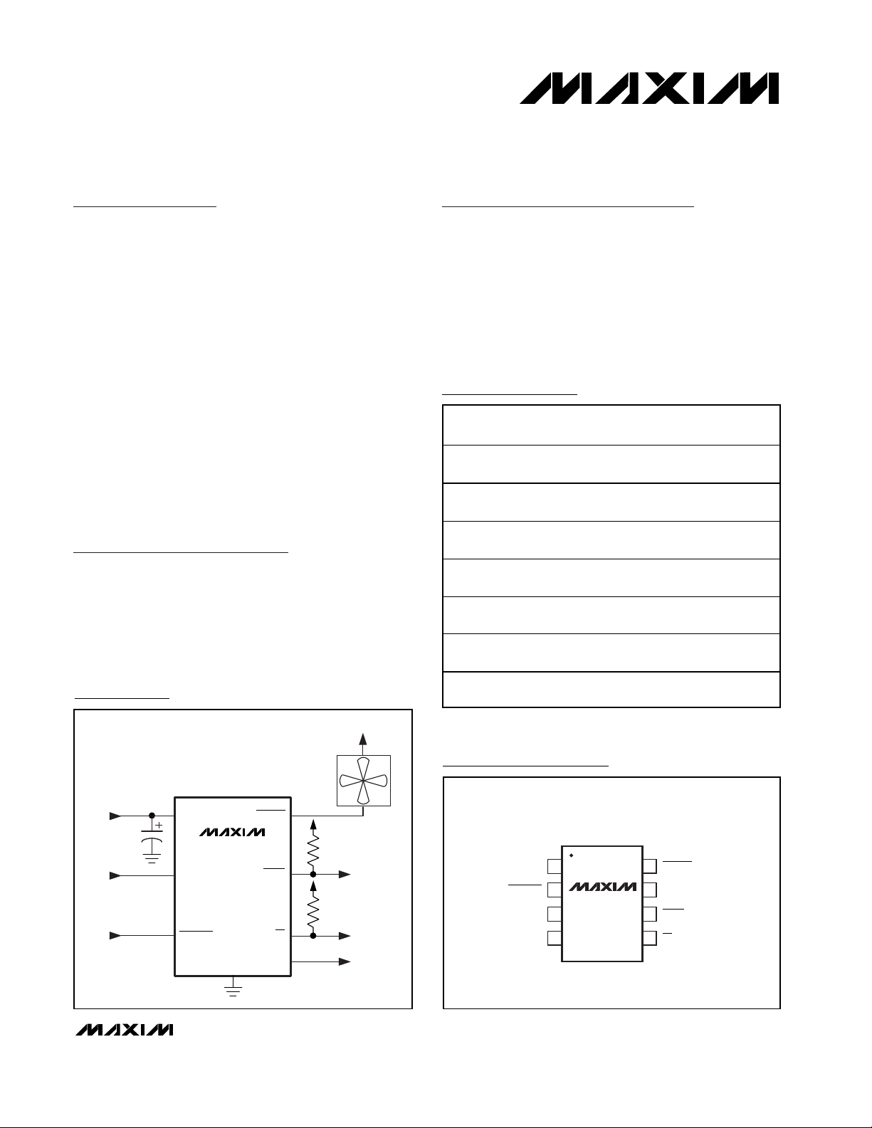
+3.3V
+4.5V TO +24V
100mA TO 250mA
COOLING FAN
100kΩ
1µF
MAX6665
FORCEON
FANOUT
WARN
OT
V
DD
100kΩ
Typical Operating Circuit
19-2056; Rev 0; 5/01
Ordering Information
*Exposed paddle
For pricing, delivery, and ordering information, please contact Maxim/Dallas Direct! at
1-888-629-4642, or visit Maxim’s website at www.maxim-ic.com.
PART
MAX6665ASA40
MAX6665ASA45
MAX6665ASA50
MAX6665ASA55
MAX6665ASA60
MAX6665ASA65
MAX6665ASA70
TEMP.
RANGE
-40°C to
+125°C
-40°C to
+125°C
-40°C to
+125°C
-40°C to
+125°C
-40°C to
+125°C
-40°C to
+125°C
-40°C to
+125°C
PINPACKAGE
8 SO-EP* 40°C
8 SO-EP* 45°C
8 SO-EP* 50°C
8 SO-EP* 55°C
8 SO-EP* 60°C
8 SO-EP* 65°C
8 SO-EP* 70°C
THRESHOLD
TOP VIEW
GND
FORCEON
HYST
FANON
1
2
MAX6665
3
4
SO
8
7 V
6
5
FANOUT
DD
WARN
OT
MAX6665
Fan Controller/Driver with FactoryProgrammed Temperature Thresholds
2 _______________________________________________________________________________________
ABSOLUTE MAXIMUM RATINGS
Stresses beyond those listed under “Absolute Maximum Ratings” may cause permanent damage to the device. These are stress ratings only, and functional
operation of the device at these or any other conditions beyond those indicated in the operational sections of the specifications is not implied. Exposure to
absolute maximum rating conditions for extended periods may affect device reliability.
Note 1: Specifications over temperature are guaranteed by design. Parts are 100% production tested at 10°C below the tempera-
ture threshold.
V
DD
to GND..............................................................-0.3V to +6V
FANOUT to GND ....................................................-0.3V to +28V
FORCEON, HYST, FANON to GND............-0.3V to (V
DD
+ 0.3V)
WARN, OT to GND ...................................................-0.3V to +6V
FANOUT Continuous Current............................................400mA
All Other Pins ....................................................................±20mA
Continuous Power Dissipation (T
A
= +70°C)
8-Pin SO (derate 19.6mW/°C above +70°C).............1568mW
Operating Temperature Range .........................-40°C to +125°C
Junction (storage) Temperature Range ............-65°C to +150°C
Lead Temperature (soldering, 10s) .................................+300°C
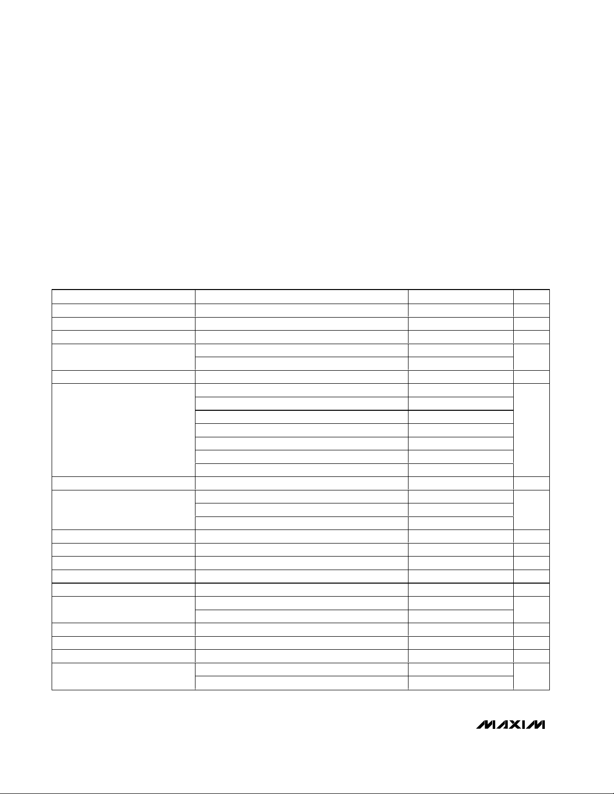
ELECTRICAL CHARACTERISTICS
(VDD= +2.7V to +5.5V, TA= -40°C to +125°C. Typical values are at VDD= +3.3V and TA= +25°C, unless otherwise noted.) (Note 1)
Supply Voltage VDD pin 2.7 5.5 V
Supply Current No load 65 200 µA
FANOUT Drive Voltage FANOUT pin 26 V
FAN OUT Outp ut C ur r ent C ap ab i l i ty
FANOUT Leakage Current V
FANOUT Threshold, T
FANOUT Threshold Error -3 ±1+3°C
FANOUT Hysteresis
WARN Threshold Relative to FANOUT temperature threshold +15 °C
OT Threshold Relative to FANOUT temperature threshold +30 °C
WARN and OT Hysteresis 2 °C
FANON Output High Voltage I
FANON Output Low Voltage I
W ARN and O T Outp ut V ol tag e Low
Open-Drain Leakage Current V
Input Low Voltage FORCEON and HYST pins 0.3V
Input High Voltage FORCEON and HYST pins 0.7V
Input Current
PARAMETER CONDITIONS MIN TYP MAX UNITS
TH
V
V
MAX6665ASA40 40
MAX6665ASA45 45
MAX6665ASA50 50
MAX6665ASA55 55
MAX6665ASA60 60
MAX6665ASA65 65
MAX6665ASA70 70
HYST is unconnected 1
HYST ≤ 0.3V
HYST ≥ 0.7V
FANON
FANON
I
WARN
I
WARN
FORCEON connected to VDD or GND -1 +1
HYST connected to V
< 0.8V 250
FANOUT
< 0.6V, T
FANOUT
= 26V, T
FANOUT
= 0.5mA source 2.0 V
= 0.5mA sink 0.7 V
= 1.2mA or I OT = 1.2mA sink 0.3
= 20mA or I OT = 20mA sink 0.5
= 5.5V or V OT = 5.5V 0.1 µA
WARN
≤ TTH +10°C, VCC ≥ +3.3V 250
A
= +60°C3µA
A
DD
DD
or GND -15 +15
DD
DD
4
8
DD
mA
°C
°C
V
V
V
µA

MAX6665
Fan Controller/Driver with Factory-
Programmed Temperature Thresholds
_______________________________________________________________________________________ 3
Typical Operating Characteristics
(V
DD
= +3.3V, unless otherwise noted.)
900
800
700
600
500
400
300
FANOUT VOLTAGE (mV)
200
100
0
10 100 1000
90
80
70
60
50
SUPPLY CURRENT (µA)
40
30
-40 0-20 20 40 60 80 100 120
FANOUT VOLTAGE vs. CURRENT
TA = +75°C
FANOUT CURRENT (mA)
VDD = +2.7V
VDD = +3.3V
VDD = +5.0V
NO-LOAD SUPPLY CURRENT
vs. TEMPERATURE
FORCEON = V
DD
VDD = +5V
VDD = +3.3V
TEMPERATURE (°C)
VDD = +2.7V
MAX6665 toc01
MAX6665 toc03
FANOUT VOLTAGE vs. SUPPLY VOLTAGE
550
FANOUT CURRENT = 250mA
500
450
400
350
FANOUT VOLTAGE (mV)
300
250
2.7 3.9 4.33.1 3.5 4.7 5.1 5.5
TA = +75°C
TA = +50°C
SUPPLY VOLTAGE (V)
TEMPERATURE THRESHOLD
DISTRIBUTION
50
MAX6665ASA55
45
100 SAMPLES
40
35
30
25
20
15
PERCENTAGE OF SAMPLES (%)
10
5
0
-2.0 -0.5-1.5 0.5-1.0 1.0 1.5 2.0 2.5-2.5 3.0-3.0
TEMPERATURE ERROR (°C)
0
MAX6665 toc02
MAX6665 toc04
MAX6665
Fan Controller/Driver with FactoryProgrammed Temperature Thresholds
4 _______________________________________________________________________________________
Detailed Description
The MAX6665 is a simple fan controller/driver that turns
on the internal power transistor when its die temperature exceeds a factory-set threshold. By connecting a
small (typically 5V to 12V, 100mA to 250mA) cooling
fan to FANOUT, a simple on/off fan-control system is
created. FANOUT drives the fan’s low side. The fan’s
positive supply pin should be connected to its normal
power-supply voltage (up to 24V nominal).
To turn the fan on when the MAX6665’s die temperature
is less than the threshold voltage, drive FORCEON low.
This overrides the internal control circuitry and allows
an external device to activate the fan. FANON is an
active-high push-pull logic output that goes high when
the fan is turned on, either when temperature exceeds
the threshold or the fan is forced on.
WARN is an active-low, open-drain digital output that
indicates the MAX6665’s die temperature exceeds
15°C above the fan trip threshold. WARN output serves
as a warning that the system temperature has continued to rise well above the fan activation temperature.
OT is an active-low open-drain digital output that indicates the MAX6665’s die temperature exceeds 30°C
above the fan trip threshold. It serves as a thermal shutdown output to the system in case of excessive temperature rise. Figure 1 shows a typical application circuit
for a high-reliability, fail-safe temperature monitor.
Applications Information
Thermal Considerations and Hysteresis
The temperature comparator has hysteresis to prevent
small temperature changes near the threshold temperature from causing the fan to turn on and off repeatedly
over short periods of time. The FANOUT pin goes
active and powers the fan when the MAX6665’s die
temperature exceeds the factory-programmed trip temperature. As the cooling fan operates, the circuit board
temperature should decrease, which in turn causes the
MAX6665’s die temperature to decrease. When the die
temperature is equal to the trip threshold minus the
hysteresis, the FANOUT pin turns the fan off, removing
power from the fan. The HYST pin sets the amount of
hysteresis to 1°C, 4°C, or 8°C by letting the pin float or
connecting to GND or VDD, respectively. This allows
the amount of hysteresis to be matched to the cooling
and noise requirements of the system.
Hysteresis is also affected by self-heating of the
MAX6665’s die. The fan current flowing through the onchip power transistor causes the die temperature to
increase. For example, assume the MAX6665 controls
a 125mA fan. When the fan is operating, the voltage
drop across the output transistor is typically under
250mV. At 250mV, the power dissipation is 31.25mW.
The thermal resistance of the MAX6665 package (with
EP soldered) is 51°C/W, so the die temperature
Pin Description
PIN NAME FUNCTION
1 GND Ground
2 FORCEON
3 HYST
4 FANON
5 OT
6 WARN
7VDDSupply Voltage. Bypass with a 1µF capacitor to GND as close to VDD pin as possible.
8 FANOUT Fan-Switch (Driver) Output. Connect to the low side of a fan.
Exposed
Paddle
GND
Force Fan On Input. Set FORCEON low to force the fan switch on. Set FORCEON high for normal
operation.
Three-State Hysteresis Input. Connect HYST to V
unconnected for 1°C hysteresis.
Fan-On Indicator Output. Push-pull output. FANON is high when the fan switch is on. FANON is low
when the fan switch is off.
Overtemperature Output. Active-low when the temperature is 30°C above the fan threshold. Opendrain output, requires resistive pullup.
Overtemperature Warning Output. Active-low when the temperature is 15°C above the fan
threshold. Open-drain output, requires resistive pullup.
Ground
for 8°C, GND for 4°C, and leave HYST
DD

increases by a maximum of:
51°C/W x 0.03125W = 1.59°C
Therefore, the effective hysteresis is about 1.59°C higher than the hysteresis selected by the HYST pin. For
example, setting the HYST pin for 8°C of hysteresis
results in an effective hysteresis of about 9.6°C.
A larger fan with a power-supply current of 250mA
causes a maximum voltage drop of 0.6V at the output
pin. This results in 150mW power dissipation and the
die temperature increases by:
51°C/W x 0.150W = 7.65°C
If the HYST pin has been set for 8°C of hysteresis, the
total effective hysteresis will be about 15.7°C.
Using fans with somewhat higher operating current
than 250mA results in higher voltage across the output
transistor. The increased power dissipation caused by
the higher current and voltage levels will increase selfheating, thereby increasing the effective hysteresis.
When using higher-power fans, be sure that the
MAX6665’s power dissipation does not cause so much
self-heating that the MAX6665 stays on constantly.
Locating the MAX6665
The location of the MAX6665 in the system affects its
operation. Because the fan is turned on and off based
on the MAX6665’s die temperature, place the MAX6665
close to major heat-generating components in the system—a high-speed CPU or a power device, for example. A higher supply voltage reduces the FANOUT
voltage, which reduces the self-heating effects.
The die temperature of the MAX6665 tracks the temperature of its leads and the EP. If it is soldered to a PC board,
it quickly reaches the temperature of the traces in that
section of the circuit board. Air temperature affects the die
temperature. Since the plastic package does not conduct
heat as well as the leads, the effect of air temperature is
much less than that of lead temperature.
Layout Issues
The MAX6665’s GND pin is ground return for the fan driver and the device. Large fan current induces noise
(ground bounce) to the MAX6665. Bypass VDDto GND
with a 1µF tantalum capacitor located as close to the
MAX6665 as possible. For long V
DD
and GND lines, an
additional bypass capacitor may be needed. The bypass
capacitor reduces GND noise. The EP is internally connected to the GND pin. Solder the EP to the ground plane
for better electrical and thermal performance.
MAX6665
Fan Controller/Driver with Factory-
Programmed Temperature Thresholds
_______________________________________________________________________________________ 5
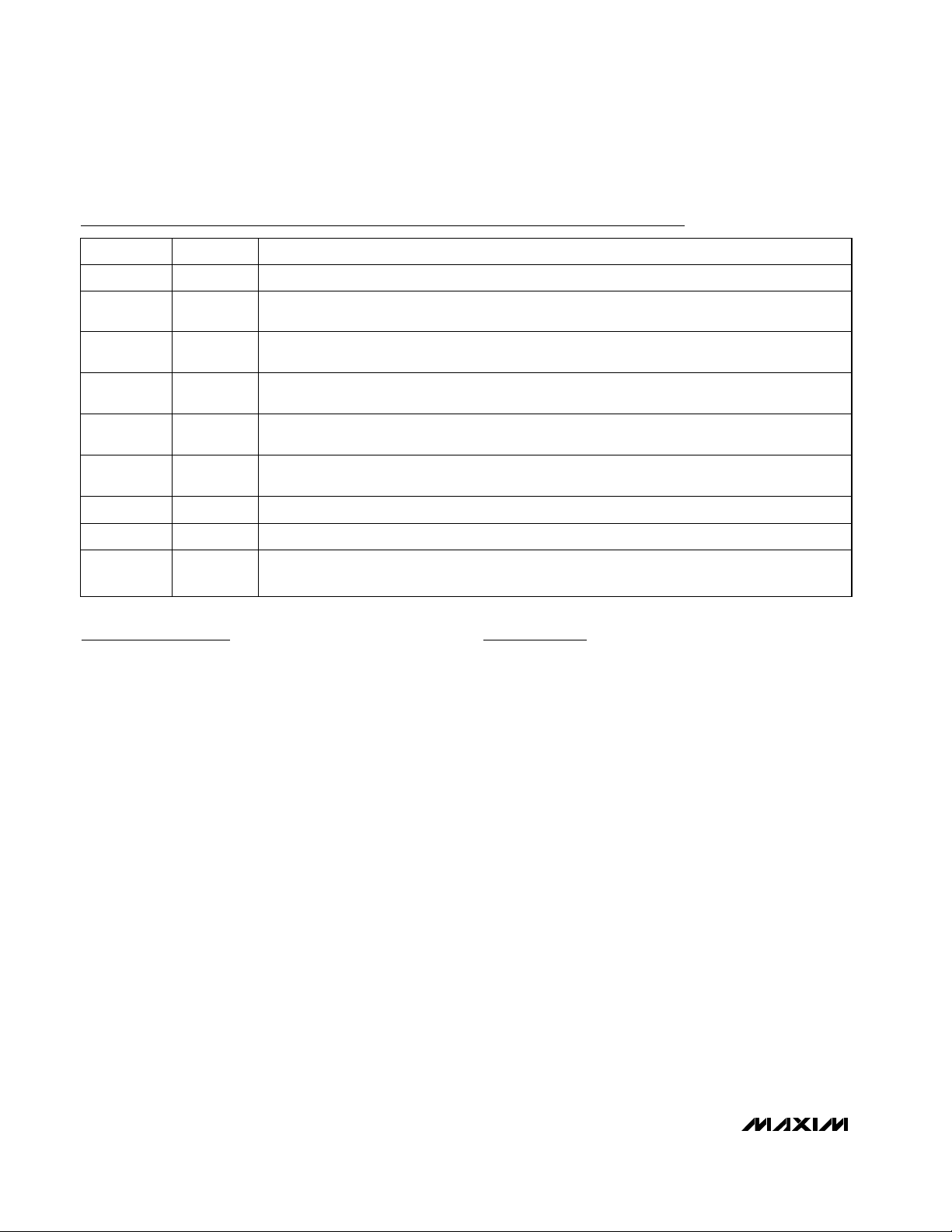
Figure 1. High-Reliability, Fail-Safe Fan Controller and Temperature Monitor
+4.5V TO +24V
100mA TO 250mA
COOLING FAN
+3.3V
1µF
V
DD
HYST
FORCEON
MAX6665
GND
FANOUT
WARN
FANON
V
DD
100kΩ
V
DD
100kΩ
OT
SYSTEM POWER
SHUTDOWN
µP
I/O
I/O

MAX6665
Fan Controller/Driver with FactoryProgrammed Temperature Thresholds
Maxim cannot assume responsibility for use of any circuitry other than circuitry entirely embodied in a Maxim product. No circuit patent licenses are
implied. Maxim reserves the right to change the circuitry and specifications without notice at any time.
6 _____________________Maxim Integrated Products, 120 San Gabriel Drive, Sunnyvale, CA 94086 408-737-7600
© 2001 Maxim Integrated Products Printed USA is a registered trademark of Maxim Integrated Products.
Package Information
Chip Information
TRANSISTOR COUNT: 1543 MOS
119 BIPOLAR
PROCESS: BiCMOS
8L, SOIC EXP. PAD.EPS
 Loading...