


General Description
The MAX6643/MAX6644/MAX6645 monitor temperature
and automatically adjust fan speed to ensure optimum
cooling while minimizing acoustic noise from the fan.
Each device measures two temperature locations.
The MAX6643/MAX6644/MAX6645 generate a PWM
waveform that drives an external power transistor, which
in turn modulates the fan’s power supply. The
MAX6643/MAX6644/MAX6645 monitor temperature and
adjust the duty cycle of the PWM output waveform to control the fan’s speed according to the cooling needs of the
system. The MAX6643 monitors its own die temperature
and an optional external transistor’s temperature, while the
MAX6644 and MAX6645 each monitor the temperatures
of one or two external diode-connected transistors.
The MAX6643 and MAX6644 have nine selectable trip
temperatures (in 5°C increments). The MAX6645 is factory programmed and is not pin selectable.
All versions include an overtemperature output (OT).
OT can be used for warning or system shutdown. The
MAX6643 also features a FULLSPD input that forces the
PWM duty cycle to 100%. The MAX6643/MAX6644/
MAX6645 also feature a FANFAIL output that indicates
a failed fan. See the Selector Guide for a complete list
of each device’s functions.
The MAX6643 and MAX6644 are available in a small
16-pin QSOP package and the MAX6645 is available in
a 10-pin µMAX®package. All versions operate from
3.0V to 5.5V supply voltages and consume 500µA (typ)
supply current.
Applications
Networking Equipment
Storage Equipment
Servers
Desktop Computers
Workstations
Features
♦ Simple, Automatic Fan-Speed Control
♦ Internal and External Temperature Sensing
♦ Detect Fan Failure Through Locked-Rotor Output,
Tachometer Output, or Fan-Supply Current
Sensing
♦ Multiple, 1.6% Output Duty-Cycle Steps for Low
Audibility of Fan-Speed Changes
♦ Pin-Selectable or Factory-Selectable Low-
Temperature Fan Threshold
♦ Pin-Selectable or Factory-Selectable High-
Temperature Fan Threshold
♦ Spin-Up Time Ensures Fan Start
♦ Fan-Start Delay Minimizes Power-Supply Load at
Power-Up
♦ 32Hz PWM Output
♦ Controlled Duty-Cycle Rate-of-Change Ensures
Good Acoustic Performance
♦ 2°C Temperature-Measurement Accuracy
♦ FULLSPD/FULLSPD Input Sets PWM to 100%
♦ Pin-Selectable OT Output Threshold
♦ 16-Pin QSOP and 10-Pin µMAX Packages
MAX6643/MAX6644/MAX6645
Automatic PWM Fan-Speed Controllers with
Overtemperature Output
________________________________________________________________ Maxim Integrated Products 1
Ordering Information
19-3305; Rev 2; 3/07
For pricing, delivery, and ordering information, please contact Maxim Direct at 1-888-629-4642,
or visit Maxim’s website at www.maxim-ic.com.
EVALUATION KIT
AVAILABLE
Pin Configurations, Typical Operating Circuit, and Selector
Guide appear at end of data sheet.
µMAX is a registered trademark of Maxim Integrated Products, Inc.
PART TEMP RANGE
MAX6643LBFAEE -40°C to +125°C 16 QSOP E16-1
MAX6643LBBAEE -40°C to +125°C 16 QSOP E16-1
MAX6644LBAAEE -40°C to +125°C 16 QSOP E16-1
MAX6645ABFAUB -40°C to +125°C 10 µMAX U10-2
PINPACKAGE
PKG
CODE
MAX6643/MAX6644/MAX6645
Automatic PWM Fan-Speed Controllers with
Overtemperature Output
2 _______________________________________________________________________________________
ABSOLUTE MAXIMUM RATINGS
ELECTRICAL CHARACTERISTICS
(VDD= +3.0V to +5.5V, TA= -40°C to +125°C, unless otherwise noted. Typical values are at VDD= +3.3V, TA= +25°C.) (Note 1)
Stresses beyond those listed under “Absolute Maximum Ratings” may cause permanent damage to the device. These are stress ratings only, and functional
operation of the device at these or any other conditions beyond those indicated in the operational sections of the specifications is not implied. Exposure to
absolute maximum rating conditions for extended periods may affect device reliability.
VDDto GND..............................................................-0.3V to +6V
PWM_OUT, OT, and FANFAIL to GND.....................-0.3V to +6V
FAN_IN1 and FAN_IN2 to GND...........................-0.3V to +13.2V
DXP_ to GND.........................................................-0.3V to +0.8V
FULLSPD, FULLSPD, TH_, TL_, TACHSET,
and OT_ to GND ..................................-0.3V to +(V
DD
+ 0.3V)
FANFAIL, OT Current..........................................-1mA to +50mA
Continuous Power Dissipation (T
A
= +70°C)
16-Pin QSOP (derate 8.3mW/°C above +70°C).......... 667mW
10-Pin µMAX (derate 5.6mW/°C above +70°C) ...........444mW
Operating Temperature Range .........................-40°C to +125°C
Junction Temperature......................................................+150°C
Storage Temperature Range ............................-65°C to +150°C
Lead Temperature (soldering, 10s) .................................+300°C
Operating Supply Voltage Range V
Remote Temperature Error
Local Temperature Error VCC = +3.3V
Temperature Error from Supply
Sensitivity
Power-On-Reset (POR) Threshold VDD falling edge 1.5 2.0 2.5 V
POR Threshold Hysteresis 90 mV
Operating Current I
Average Operating Current Duty cycle = 50%, no load 0.5 mA
Remote-Diode Sourcing Current High level 80 100 120 µA
Conversion Time 125 ms
Spin-Up Time MAX664_ _B_ _ _ _ 8 s
Startup Delay MAX664_ _B_ _ _ _ 0.5 s
Minimum Fan-Fail Tachometer
Frequency
PWM_OUT Frequency F
DIGITAL OUTPUTS (OT, FANFAIL, PWM_OUT)
Output Low Voltage (OT)V
Output Low Voltage
(FANFAIL, PWM_OUT)
Output-High Leakage Current I
PARAMETER SYMBOL CONDITIONS MIN TYP MAX UNITS
DD
= +3.3V,
S
PWM_OUT
OL
V
OL
OH
V
DD
+20°C ≤ T
+100°C
During a conversion 0.5 1 mA
I
SINK
I
SINK
I
SINK
VOH = 3.3V 1 µA
RJ
= 1mA 0.4 V
= 6mA 0.5
= 1mA 0.4
TA = +20°C to +60°C ±2
≤
= 0°C to +125°C ±3
T
A
TA = +10°C to +70°C ±2.5
T
= 0°C to +125°C ±3.5
A
+3.0 +5.5 V
±0.2 °C/V
16 Hz
32 Hz
°C
°C
V
MAX6643/MAX6644/MAX6645
Automatic PWM Fan-Speed Controllers with
Overtemperature Output
_______________________________________________________________________________________ 3
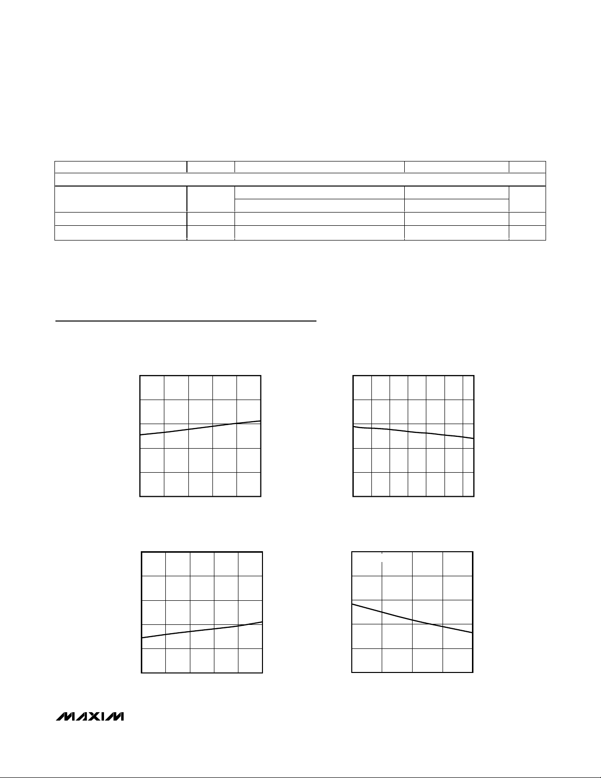
Typical Operating Characteristics
(TA = +25°C, unless otherwise noted.)
ELECTRICAL CHARACTERISTICS (continued)
(VDD= +3.0V to +5.5V, TA= -40°C to +125°C, unless otherwise noted. Typical values are at VDD= +3.3V, TA= +25°C.) (Note 1)
Note 1: All parameters tested at TA= +25°C. Specifications over temperature are guaranteed by design.
DIGITAL INPUTS (FULLSPD, FULLSPD, TACHSET)
Logic-Input High V
Logic-Input Low V
Input Leakage Current VIN = GND or V
PARAMETER SYMBOL CONDITIONS MIN TYP MAX UNITS
VDD = 5.5V 3.65
IH
VDD = 3.0V 2.2
VDD = 3.0V 0.8 V
IL
DD
-1 +1 µA
OPERATING SUPPLY CURRENT
vs. SUPPLY VOLTAGE
400
360
MAX6643 toc01
32.0
31.8
PWMOUT FREQUENCY
vs. DIE TEMPERATURE
MAX6643 toc02
V
320
280
SUPPLY CURRENT (μA)
240
200
3.0 5.5
SUPPLY VOLTAGE (V)
PWMOUT FREQUENCY
vs. SUPPLY VOLTAGE
35
34
33
32
PWMOUT FREQUENCY (Hz)
31
30
3.0 5.5
SUPPLY VOLTAGE (V)
31.6
31.4
PWMOUT FREQUENCY (Hz)
31.2
5.04.54.03.5
31.0
-40
10085603510-15
TEMPERATURE (°C)
TRIP-THRESHOLD ERROR
vs. TRIP TEMPERATURE
1.0
MAX664_L VERSIONS
MAX6643 toc03
5.04.54.03.5
0.6
0.2
-0.2
TRIP-THRESHOLD ERROR (°C)
-0.6
-1.0
20 100
TRIP TEMPERATURE (°C)
806040
MAX6643 toc04

MAX6643/MAX6644/MAX6645
Automatic PWM Fan-Speed Controllers with
Overtemperature Output
4 _______________________________________________________________________________________
Pin Description
PIN
MAX6643 MAX6644 MAX6645
1, 15 1, 15 — TH1, TH2
NAME FUNCTION
High-Temperature Threshold Inputs. Connect to V
leave unconnected to select the upper fan-control trip
temperature (T
), in 5°C increments. See Table 1.
HIGH
DD
, GND, or
Low-Temperature Threshold Inputs. Connect to V
2, 3 2, 3 — TL2, TL1
441FANFAIL
5 5 2 TACHSET
6 — — FULLSPD
———FULLSPD
7 7 4 GND Ground
8 — — DXP
— 6, 8 3, 5 DXP2, DXP1
996OT
10, 11 10, 11 7, 8
FAN_IN2,
FAN_IN1
leave unconnected to select the lower fan-control trip
temperature (T
Fan-Fail Alarm Output. FANFAIL is an active-low, open-drain
output. If the FAN_IN_ detects a fan failure, the FANFAIL output
asserts low.
FAN_IN_ Control Input. TACHSET controls what type of fan-fail
condition is being detected. Connect TACHSET to V
or leave floating to set locked rotor, current sense, or
tachometer configurations (see Table 3).
Active-High Logic Input. When pulled high, the fan runs at
100% duty cycle.
Active-Low Logic Input. When pulled low, the fan runs at 100%
duty cycle.
C om b i ned C ur r ent S our ce and A/D P osi ti ve Inp ut for Rem ote
D i od e. C onnect to anod e of r em ote d i od e- connected
tem p er atur e- sensi ng tr ansi stor . C onnect to G N D i f no r em ote
d i od e i s used . P l ace a 2200p F cap aci tor b etw een D X P _ and
G N D for noi se fi l ter i ng .
Active-Low, Open-Drain Overtemperature Output. When OT
threshold is exceeded, OT pulls low.
Fan- S ense Inp ut. FAN _IN _ can b e confi g ur ed to m oni tor ei ther a
fan’ s l og i c- l evel l ocked - r otor outp ut, tachom eter outp ut, or senser esi stor w avefor m to d etect fan fai l ur e. The M AX 6643’ s FAN _IN _
i np ut can m oni tor onl y tachom eter si g nal s. The M AX 6644 and the
M AX 6645 can m oni tor any one of the thr ee si g nal typ es as
confi g ur ed usi ng the TAC H S E T i np ut.
), in 5°C increments. See Table 2.
LOW
, GND, or
DD
DD
, GND,
Detailed Description
The MAX6643/MAX6644/MAX6645 measure temperature
and automatically adjust fan speed to ensure optimum
cooling while minimizing acoustic noise from the fan.
The MAX6643/MAX6644/MAX6645 generate a PWM
waveform that drives an external power transistor,
which in turn modulates the fan’s power supply. The
MAX6643/MAX6644/MAX6645 monitor temperature and
adjust the duty cycle of the PWM output waveform to
control the fan’s speed according to the cooling needs
of the system. The MAX6643 monitors its own die temperature and an optional external transistor’s temperature, while the MAX6644 and MAX6645 each monitor
the temperatures of one or two external diode-connected transistors.
Temperature Sensor
The pn junction-based temperature sensor can measure temperatures up to two pn junctions. The
MAX6643 measures the temperature of an external
diode-connected transistor, as well as its internal temperature. The MAX6644 and MAX6645 measure the
temperature of two external diode-connected transistors. The temperature is measured at a rate of 1Hz.
If an external “diode” pin is shorted to ground or left
unconnected, the temperature is read as 0°C. Since the
larger of the two temperatures prevails, a faulty or
unconnected diode is not used for calculating fan
speed or determining overtemperature faults.
PWM Output
The larger of the two measured temperatures is always
used for fan control. The temperature is compared to
three thresholds: the high-temperature threshold (T
HIGH
),
the low-temperature threshold (T
LOW
), and the overtem-
perature threshold, OT. The OT comparison is done once
per second, whereas the comparisons with fan-control
thresholds T
HIGH
and T
LOW
are done once every 4s.
The duty-cycle variation of PWM_OUT from 0% to 100%
is divided into 64 steps. If the temperature measured
exceeds the threshold T
HIGH
, the PWM_OUT duty cycle
is incremented by one step, i.e., approximately 1.5%
(100/64). Similarly, if the temperature measured is below
the threshold T
LOW
, the duty cycle is decremented by
one step (1.5%). Since the T
HIGH
and T
LOW
comparisons are done only once every 4s, the maximum rate of
change of duty cycle is 0.4% per second.
Tables 1 and 2 show the °C value assigned to the TH_
and TL_ input combinations.
MAX6643/MAX6644/MAX6645
Automatic PWM Fan-Speed Controllers with
Overtemperature Output
_______________________________________________________________________________________ 5
Pin Description (continued)
Table 1. Setting T
HIGH
(MAX6643 and MAX6644)
High-Z = High impedance.
PIN
MAX6643 MAX6644 MAX6645
12 12 9 PWM_OUT
13, 14 13, 14 — OT2, OT1
16 16 10 V
NAME FUNCTION
DD
PWM Output for Driving External Power Transistor. Connect to
the gate of an n-channel MOSFET or to the base of an npn.
PWM_OUT requires a pullup resistor. The pullup resistor can
be connected to a supply voltage as high as 5.5V, regardless
of the supply voltage.
Overtemperature Threshold Inputs. Connect to V
leave unconnected to select the upper-limit OT fault output trip
temperature, in 5°C increments. See Table 4.
Power-Supply Input. 3.3V nominal. Bypass VDD to GND with a
0.1µF capacitor.
, GND, or
DD
TH2 TH1
0 0 20 40
0 High-Z 25 45
0 1 30 50
High-Z 0 35 55
High-Z High-Z 40 60
High-Z 1 45 65
1 0 50 70
1 High-Z 55 75
1 1 60 80
T
HIGH
L SUFFIX
(°C)
T
(°C)
HIGH
H SUFFIX
MAX6643/MAX6644/MAX6645
There are two options for the behavior of the PWM outputs at power-up. Option 1 (minimum duty cycle = 0):
at power-up, the PWM duty cycle is zero. Option 2
(minimum duty cycle = the start duty cycle): at powerup, there is a startup delay, after which the duty cycle
goes to 100% for the spin-up period. After the startup
delay and spin-up, the duty cycle drops to its minimum
value. The minimum duty cycle is in the 0% to 50%
range (see the Selector Guide).
To control fan speed based on temperature, T
HIGH
is
set to the temperature beyond which the fan should spin
at 100%. T
LOW
is set to the temperature below which
the duty cycle can be reduced to its minimum value.
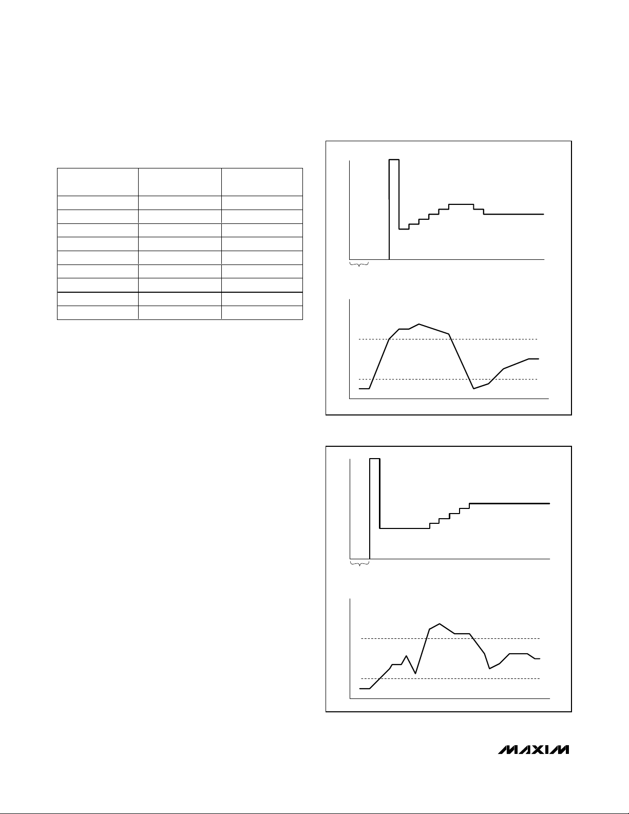
After power-up and spin-up (if applicable), the duty
cycle reduces to its minimum value (either 0% or the
start duty cycle). For option 1 (minimum duty cycle = 0),
if the measured temperature remains below T
HIGH
, the
duty cycle remains at zero (see Figure 1). If the temperature increases above T
HIGH
, the duty cycle goes to
100% for the spin-up period, and then goes to the start
duty cycle (for example, 40%). If the measured temperature remains above T
HIGH
when temperature is next
measured (4s later), the duty cycle begins to increase,
incrementing by 1.5% every 4s until the fan is spinning
fast enough to reduce the temperature below T
HIGH
.
For option 2 (minimum duty cycle = start duty cycle), if
the measured temperature remains below T
HIGH
, the
duty cycle does not increase and the fan continues to
run at a slow speed. If the temperature increases
above T
HIGH
, the duty cycle begins to increase, incrementing by 1.5% every 4s until the fan is spinning fast
enough to reduce the temperature below T
HIGH
(see
Figure 2). In both cases, if only a small amount of extra
cooling is necessary to reduce the temperature below
Automatic PWM Fan-Speed Controllers with
Overtemperature Output
6 _______________________________________________________________________________________
Table 2. Setting T
LOW
(MAX6643 and MAX6644)
Figure 1. Temperature-Controlled Duty-Cycle Change with
Minimum Duty Cycle 30%
Figure 2. Temperature-Controlled Duty-Cycle Change with
Minimum Duty Cycle 30%
High-Z = High impedance.
(°C)
T
TL2 TL1
0015
0 High-Z 20
0125
High-Z 0 30
High-Z High-Z 35
High-Z 1 40
1045
1 High-Z 50
1155
LOW
L SUFFIX
DUTY CYCLETEMPERATURE
DUTY CYCLETEMPERATURE
SPIN-UP
STARTUP
SPIN-UP
STARTUP
MAX664_B HAS 30% PWM_OUT DUTY CYCLE DURING STARTUP.
TIME
TIME
TIME
TIME
T
HIGH
T
LOW
T
HIGH
T
LOW

T
HIGH
, the duty cycle may increase just a few percent
above the minimum duty cycle. If the power dissipation or
ambient temperature increases to a high-enough value,
the duty cycle may eventually need to increase to 100%.
If the ambient temperature or the power dissipation
reduces to the point that the measured temperature is
less than T
LOW
, the duty cycle begins slowly decrementing until either the duty cycle reaches its minimum
value or the temperature rises above T
LOW
.
The small duty-cycle increments and slow rate-ofchange of duty cycle (1.5% maximum per 4s) reduce
the likelihood that the process of fan-speed control is
acoustically objectionable. The “dead band” between
T
LOW
and T
HIGH
keeps the fan speed constant when
the temperature is undergoing small changes, thus
making the fan-control process even less audible.
Fan-Fail Sensing
The MAX6643/MAX6644/MAX6645 feature a FANFAIL
output. The FANFAIL output is an active-low, opendrain alarm. The MAX6643/MAX6644/MAX6645 detect
fan failure either by measuring the fan’s speed and recognizing when it is too low, or by detecting a lockedrotor logic signal from the fan. Fan-failure detection is
enabled only when the duty cycle of the PWM drive signal is equal to 100%. This happens during the spin-up
period when the fan first turns on and whenever the
temperature is above T
HIGH
long enough that the duty
cycle reaches 100%.
Many fans have open-drain tachometer outputs that
produce periodic pulses (usually two pulses per revolution) as the fan spins. These tachometer pulses are
monitored by the FAN_IN_ inputs to detect fan failures.
If a 2-wire fan with no tachometer output is used, the
fan’s speed can be monitored by using an external
sense resistor at the source of the driving FET (see
Figure 3). In this manner, the variation in the current
flowing through the fan develops a periodic voltage
waveform across the sense resistor. This periodic
waveform is then highpass filtered and AC-coupled to
the FAN_IN_ input. Any variations in the waveform that
have an amplitude of more than ±150mV are converted
to digital pulses. The frequency of these digital pulses
is directly related to the speed of the rotation of the fan
and can be used to detect fan failure.
Note that the value of the sense resistor must be
matched to the characteristics of the fan’s current
waveform. Choose a resistor that produces voltage
variations of at least ±200mV to ensure that the fan’s
operation can be reliably detected. Note that while
most fans have current waveforms that can be used
with this detection method, there may be some that do
not produce reliable tachometer signals. If a 2-wire fan
is to be used with fault detection, be sure that the fan is
compatible with this technique.
To detect fan failure, the analog sense-conditioned
pulses or the tachometer pulses are deglitched and
counted for 2s while the duty cycle is 100% (either during spin-up or when the duty cycle rises to 100% due to
measured temperature). If more than 32 pulses are
counted (corresponding to 480rpm for a fan that produces two pulses per revolution), the fan is assumed to
be functioning normally. If fewer than 32 pulses are
received, the FANFAIL output is enabled and the PWM
duty cycle to the FET transistor is either shut down in
case of a single-fan (MAX6643) configuration or continues normal operation in case of a dual-fan configuration
(MAX6644/MAX6645).
Some fans have a locked-rotor logic output instead of a
tachometer output. If a locked-rotor signal is to be used
to detect fan failure, that signal is monitored for 2s while
the duty cycle is 100%. If a locked-rotor signal remains
active (low) for more than 2s, the fan is assumed to
have failed.
The MAX6643/MAX6644/MAX6645 have two channels
for monitoring fan-failure signals, FAN_IN1 and
FAN_IN2. For the MAX6643, the FAN_IN_ channels
monitor a tachometer. The MAX6643’s fault sensing can
also be turned off by floating the TACHSET input.
For the MAX6644 and MAX6645, the FAN_IN1 and
FAN_IN2 channels can be configured to monitor either
a logic-level tachometer signal, the voltage waveform
on a current-sense resistor, or a locked-rotor logic signal. The TACHSET input selects which type of signal is
to be monitored (see Table 3). To disable fan-fault
sensing, TACHSET should be unconnected and
FAN_IN1 and FAN_IN2 should be connected to VDD.
OT
Output
The MAX6643/MAX6644/MAX6645 include an overtemperature output that can be used as an alarm or a
system-shutdown signal. Whenever the measured temperature exceeds the value selected using the OT programming inputs OT1 and OT2 (see Table 4), OT is
asserted. OT deasserts only after the temperature
drops below the threshold.
FULLSPD Input
The MAX6643 features a FULLSPD input. Pulling FULLSPD high forces PWM_OUT to 100% duty cycle. The
FULLSPD input allows a microcontroller to force the fan
to full speed when necessary. By connecting FANFAIL
to an inverter, the MAX6643 can force other fans to
100% in multifan systems, or for an over-temperature
condition (by connecting OT inverter to FULLSPD).
MAX6643/MAX6644/MAX6645
Automatic PWM Fan-Speed Controllers with
Overtemperature Output
_______________________________________________________________________________________ 7

MAX6643/MAX6644/MAX6645
Applications Information
Figures 3–6 show various configurations.
Remote-Diode Considerations
When using an external thermal diode, temperature
accuracy depends upon having a good-quality, diodeconnected, small-signal transistor. Accuracy has been
experimentally verified for a variety of discrete smallsignal transistors, some of which are listed in Table 5.
The MAX6643/MAX6644/MAX6645 can also directly
measure the die temperature of CPUs and other ICs
with on-board temperature-sensing diodes.
The transistor must be a small-signal type with a relatively high forward voltage. This ensures that the input
voltage is within the ADC input voltage range. The forward voltage must be greater than 0.25V at 10µA at the
highest expected temperature. The forward voltage
must be less than 0.95V at 100µA at the lowest expected temperature. The base resistance has to be less
than 100Ω. Tight specification of forward-current gain
(+50 to +150, for example) indicates that the manufacturer has good process control and that the devices
have consistent characteristics.
Effect of Ideality Factor
The accuracy of the remote temperature measurements
depends on the ideality factor (n) of the remote diode
(actually a transistor). The MAX6643/MAX6644/MAX6645
are optimized for n = 1.01, which is typical of many discrete 2N3904 and 2N3906 transistors. It is also near the
ideality factors of many widely available CPUs, GPUs, and
FPGAs. However, any time a sense transistor with a different ideality factor is used, the output data is different.
Fortunately, the difference is predictable. Assume a
remote-diode sensor designed for a nominal ideality factor n
NOMINAL
is used to measure the temperature of a
diode with a different ideality factor, n
1
. The measured
temperature T
M
can be corrected using:
where temperature is measured in Kelvin.
As mentioned above, the nominal ideality factor of the
MAX6643/MAX6644/MAX6645 is 1.01. As an example,
assume the MAX6643/MAX6644/MAX6645 are configured with a CPU that has an ideality factor of 1.008. If
the diode has no series resistance, the measured data
is related to the real temperature as follows:
For a real temperature of +60°C (333.15K), the measured temperature is 59.33°C (332.49K), which is an
error of -0.66°C.
Automatic PWM Fan-Speed Controllers with
Overtemperature Output
8 _______________________________________________________________________________________
Table 5. Remote-Sensor Transistor
Manufacturers
Table 4. Setting the Overtemperature
Thresholds (T
OVERT
) (MAX6643 and MAX6644)
Table 3. Configuring the FAN_IN_ Inputs with TACHSET
High-Z = high impedance
TACHSET
MAX6643 Tachometer Tachometer
MAX6644 Tachometer Tachometer Current sense Current sense Locked rotor Locked rotor
MAX6645 Tachometer Tachometer Current sense Current sense Locked rotor Locked rotor
FAN_IN1 FAN_IN2 FAN_IN1 FAN_IN2 FAN_IN1 FAN_IN2
VDD GND UNCONNECTED
Do not connect
to GND
Do not connect
to GND
Disables fan-
failure detection
Disables fan-
failure detection
OT2 OT1
0060
0 High-Z 65
0170
High-Z 0 75
High-Z High-Z 80
High-Z 1 85
1090
1 High-Z 95
1 1 100
T
(°C)
OVERT
L SUFFIX
Central Semiconductor (USA) CMPT3906
Rohm Semiconductor (USA) SST3906
Samsung (Korea) KST3906-TF
Siemens (Germany) SMBT3906
TT
ACTUAL M
MANUFACTURER MODEL NO.
n
1
1.01
⎛
⎜
⎝
1.008
⎞
⎟
⎠
⎞
=
T
()
⎟
⎠
TT
=
M ACTUAL
⎛
n
=
NOMINAL
.1 00198
⎜
n
⎝
⎛
⎜
n
⎝
NOMINAL
⎞
T
=
MM
⎟
⎠
1
MAX6643/MAX6644/MAX6645
Automatic PWM Fan-Speed Controllers with
Overtemperature Output
_______________________________________________________________________________________ 9
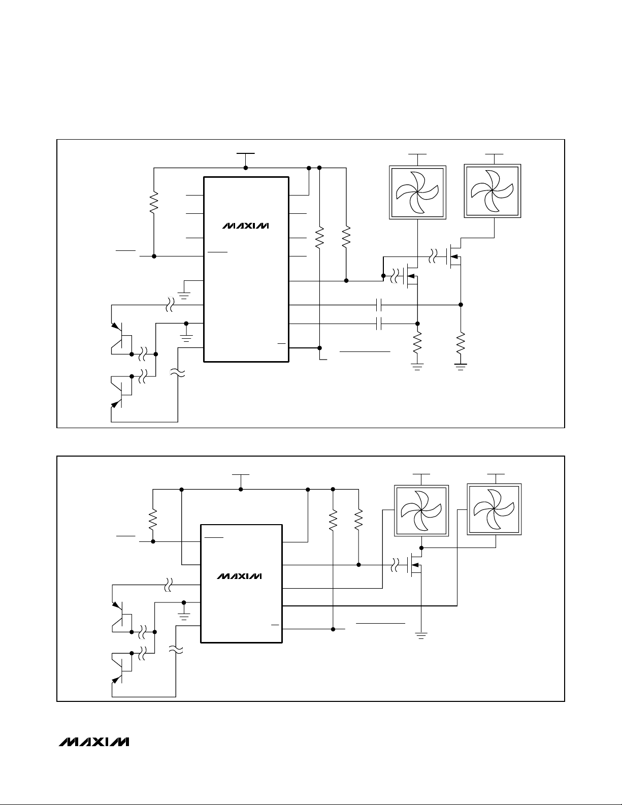
Figure 3. MAX6644 Using Two External Transistors to Measure Remote Temperatures and Control Two 2-Wire Fans. The fan’s powersupply current is monitored to detect failure of either fan. Connect pin 10 to pin 11 if only one fan is used.
Figure 4. MAX6645 Using Two External Transistors to Measure Remote Temperatures and Control Two 2-Wire Cooling Fans. The
fan’s power-supply current is monitored to detect failure of either fan. Connect FAN_IN1 to FAN_IN2 if only one fan is used.
TO FANFAIL
ALARM
4.7kΩ
1
2
3
4
5
6
7
8
V
DD
TH1
TL2
TL1
FANFAIL
TACHSET
DXP2
GND
DXP1
(+3.0V TO +5.5V)
MAX6644
PWM_OUT
FAN_IN1
FAN_IN2
V
TH2
OT1
OT2
(5V OR 12V)
+V
FAN
16
DD
15
14
13
12
11
10
9
OT
4.7kΩ
4.7kΩ
CURRENT-SENSE
MODE
CURRENT-SENSE
MODE
TO OVERTEMPERATURE
ALARM
0.1μF
0.1μF
N
2.0Ω
N
2.0Ω
+V
FAN
(5V OR 12V)
(+3.0V TO +5.5V)
TO FANFAIL
ALARM
4.7kΩ
1
2
3
4
5
V
DD
FANFAIL
TACHSET
DXP2
GND
DXP1
MAX6645
V
PWM_OUT
FAN_IN1
FAN_IN2
10
DD
9
8
7
6
OT
4.7kΩ
TACHOMETER MODE
TACHOMETER MODE
4.7kΩ
TO OVERTEMPERATURE
ALARM
+V
(5V OR 12V)
FAN
+V
(5V OR 12V)
FAN
N
MAX6643/MAX6644/MAX6645
Automatic PWM Fan-Speed Controllers with
Overtemperature Output
10 ______________________________________________________________________________________
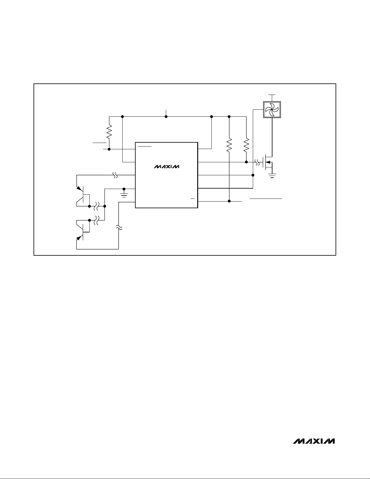
Figure 5. Using the MAX6645 to Monitor Two Fans
+V
(5V OR 12V)
FAN
V
(+3.0V TO +5.5V)
DD
4.7kΩ
TO FANFAIL
ALARM
1
2
3
4
5
FANFAIL
TACHSET
DXP2
GND
DXP1
MAX6645
PWM_OUT
FAN_IN1
FAN_IN2
10
V
DD
9
8
7
6
OT
4.7kΩ
TACHOMETER
MODE
TACHOMETER
MODE
4.7kΩ
N
TO OVERTEMPERATURE ALARM

MAX6643/MAX6644/MAX6645
Automatic PWM Fan-Speed Controllers with
Overtemperature Output
______________________________________________________________________________________ 11
Figure 6. Using Two MAX6643s, Each Controlling a Separate Fan
(5V OR 12V)
+V
FAN
V
(+3.0V TO +5.5V)
DD
TO FANFAIL
ALARM
4.7kΩ
TO FANFAIL
ALARM
4.7kΩ
1
2
3
4
5
6
7
8
1
2
3
4
5
6
7
TH1
TL2
TL1
FANFAIL
TACHSET
FULLSPD
GND
DXP
TH1
TL2
TL1
FANFAIL
TACHSET
FULLSPD
GND
MAX6643
V
(+3.0V TO +5.5V)
DD
MAX6643
V
TH2
OT1
OT2
PWM_OUT
FAN_IN1
FAN_IN2
V
TH2
OT1
OT2
PWM_OUT
FAN_IN1
FAN_IN2
16
DD
15
14
13
12
11
(TACHOMETER MODE)
(TACHOMETER MODE)
10
9
OT
16
DD
15
14
13
12
11
(TACHOMETER MODE)
(TACHOMETER MODE)
10
4.7kΩ
4.7kΩ
4.7kΩ
4.7kΩ
N
TO OVERTEMPERATURE ALARM
(5V OR 12V)
+V
FAN
N
8
DXP
9
OT
TO OVERTEMPERATURE ALARM

MAX6643/MAX6644/MAX6645
Automatic PWM Fan-Speed Controllers with
Overtemperature Output
12 ______________________________________________________________________________________
Effect of Series Resistance
Series resistance in a sense diode contributes additional errors. For nominal diode currents of 10µA and
100µA, change in the measured voltage is:
Since 1°C corresponds to 198.6µV, series resistance
contributes a temperature offset of:
Assume that the diode being measured has a series
resistance of 3Ω. The series resistance contributes an
offset of:
The effects of the ideality factor and series resistance
are additive. If the diode has an ideality factor of 1.008
and series resistance of 3Ω, the total offset can be calculated by adding error due to series resistance with
error due to ideality factor:
1.36°C - 0.66°C = 0.7°C
for a diode temperature of +60.7°C.
In this example, the effect of the series resistance and
the ideality factor partially cancel each other.
For best accuracy, the discrete transistor should be a
small-signal device with its collector connected to
base, and emitter connected to GND. Table 5 lists
examples of discrete transistors that are appropriate for
use with the MAX6643/MAX6644/MAX6645.
The transistor must have a relatively high forward voltage; otherwise, the ADC input voltage range can be violated. The forward voltage at the highest expected
temperature must be greater than 0.25V at 10µA, and at
the lowest expected temperature, the forward voltage
must be less than 0.95V at 100µA. Large power transistors must not be used. Also, ensure that the base resistance is less than 100Ω. Tight specifications for forward
current gain (50 < ß <150, for example) indicate that the
manufacturer has good process controls and that the
devices have consistent V
BE
characteristics.
ADC Noise Filtering
The integrating ADC has inherently good noise rejection, especially of low-frequency signals such as
60Hz/120Hz power-supply hum. Micropower operation
places constraints on high-frequency noise rejection.
Lay out the PCB carefully with proper external noise filtering for high-accuracy remote measurements in electrically noisy environments.
Filter high-frequency electromagnetic interference
(EMI) at the DXP pins with an external 2200pF capacitor connected between DXP, DXP1, or DXP2 and
ground. This capacitor can be increased to about
3300pF (max), including cable capacitance. A capacitance higher than 3300pF introduces errors due to the
rise time of the switched-current source.
Twisted Pairs and Shielded Cables
For remote-sensor distances longer than 8in, or in particularly noisy environments, a twisted pair is recommended. Its practical length is 6ft to 12ft (typ) before
noise becomes a problem, as tested in a noisy electronics laboratory. For longer distances, the best solution is
a shielded twisted pair like that used for audio microphones. For example, Belden 8451 works well for distances up to 100ft in a noisy environment. Connect the
twisted pair to DXP and GND and the shield to ground,
and leave the shield’s remote end unterminated. Excess
capacitance at DXP limits practical remote-sensor distances (see the Typical Operating Characteristics).
For very long cable runs, the cable’s parasitic capacitance often provides noise filtering, so the recommended 2200pF capacitor can often be removed or reduced
in value. Cable resistance also affects remote-sensor
accuracy. A 1Ω series resistance introduces about
+1/2°C error.
PCB Layout Checklist
1) Place the MAX6643/MAX6644/MAX6645 as close as
practical to the remote diode. In a noisy environment,
such as a computer motherboard, this distance can
be 4in to 8in or more, as long as the worst noise
sources (such as CRTs, clock generators, memory
buses, and ISA/PCI buses) are avoided.
2) Do not route the DXP lines next to the deflection coils
of a CRT. Also, do not route the traces across a fast
memory bus, which can easily introduce +30°C error,
even with good filtering. Otherwise, most noise
sources are fairly benign.
ΔVM =μ−μ
100 10 90
()
Ss
μ
V
90
Ω
.
=
μ
V
.
198 6
°
C
C
3
°
=μ×RAA AR
C
°
0 453
Ω
=° . .0 453 1 36
CΩΩ×

MAX6643/MAX6644/MAX6645
Automatic PWM Fan-Speed Controllers with
Overtemperature Output
______________________________________________________________________________________ 13
3) Route the DXP and GND traces parallel and close to
each other, away from any high-voltage traces such
as +12VDC. Avoid leakage currents from PCB contamination. A 20MΩ leakage path from DXP to ground
causes approximately +1°C error.
4) Route as few vias and crossunders as possible to
minimize copper/solder thermocouple effects.
5) When introducing a thermocouple, make sure that
both the DXP and the GND paths have matching
thermocouples. In general, PCB-induced thermocouples are not a serious problem. A copper solder thermocouple exhibits 3µV/°C, and it takes
approximately 200µV of voltage error at DXP/GND to
cause a +1°C measurement error, so most parasitic
thermocouple errors are swamped out.
6) Use wide traces. Narrow traces are more inductive
and tend to pick up radiated noise. The 10-mil widths
and spacings are recommended, but are not
absolutely necessary (as they offer only a minor
improvement in leakage and noise), but use them
where practical.
7) Placing an electrically clean copper ground plane
between the DXP traces and traces carrying highfrequency noise signals helps reduce EMI.
Chip Information
TRANSISTOR COUNT: 12,518
PROCESS: BiCMOS

MAX6643/MAX6644/MAX6645
Automatic PWM Fan-Speed Controllers with
Overtemperature Output
14 ______________________________________________________________________________________
Selector Guide
Pin Configurations
TOP VIEW
TH1
TL2
TL1
FANFAIL
TACHSET
FULLSPD
(FULLSPD)
GND
DXP
1
2
3
MAX6643
4
5
6
7
8
16
15
14
13
12
11
10
9
V
DD
TH2
OT1
OT2
PWM_OUT
FAN_IN1
FAN_IN2
OT
QSOP
() ARE FOR MAX6643_A ONLY.
PART
MAX6643
LBFAEE
MAX6643
LBBAEE
TIME (s)
STARTUP
PACKAGE-PINS
SPIN-UP
DELAY (s)
START DUTY
QSOP-16 0.5 8 40 40
QSOP-16 0.5 8 30 30
TH1
TL2
TL1
FANFAIL
TACHSET
DXP2
GND
DXP1
CYCLE (%)
CYCLE (%)
MINIMUM DUTY
1
2
3
4
5
6
7
8
Remote,
Remote,
MAX6644
QSOP
CHANNELS
15 to5520 to6060 to
local
15 to5520 to6060 to
local
TL (°C)
16
15
14
13
12
11
10
9
V
DD
TH2
OT1
OT2
PWM_OUT
FAN_IN1
FAN_IN2
OT
TH (°C)
FANFAIL
TACHSET
DXP2
100
100
1
2
MAX6645
3
4
5
10
9
8
7
6
V
DD
PWM_OUT
FAN_IN1
FAN_IN2GND
OTDXP1
μMAX
OT (°C)
FULLSPD
POLARITY
FULLSPD Tach/off Tach/off
FULLSPD Tach/off Tach/off
FAN_IN1
FAN_IN2
MAX6644
LBAAEE
M AX 6645
ABFAU B
QSOP-16 0.5 8 30 0
µMAX-10 0.5 8 40 40
Remote,
remote
Remote,
remote
15 to5520 to6060 to
100
45 50 75 —
—
Locked
r otor /tach/
cur r ent
sense
Locked
r otor /tach/
cur r ent
sense
Locked
r otor /tach/
cur r ent
sense
Locked
r otor /tach/
cur r ent
sense

MAX6643/MAX6644/MAX6645
Automatic PWM Fan-Speed Controllers with
Overtemperature Output
______________________________________________________________________________________ 15
Block Diagram
TO FANFAIL
ALARM
MAX6643
TH1
16
15
14
13
12
11
(TACHOMETER MODE)
(TACHOMETER MODE)
TO OVERTEMPERATURE ALARM
10
9
TL2
TL1
FANFAIL
TACHSET
FULLSPD
GND
DXP
V
DD
VDD (+3.0V TO +5.5V)
+V
FAN
(5V OR 12V)
1
2
3
4
5
6
7
8
TH2
OT1
OT2
PWM_OUT
FAN_IN1
FAN_IN2
OT
4.7kΩ
4.7kΩ
4.7kΩ
N
Typical Operating Circuit
DXP1/(DXP)
DXP2
() ARE FOR MAX6643 ONLY.
TEMPERATURE
SENSOR
TEMPERATURE
MAX6643
MAX6644
MAX6645
LOGIC
OT TH TL
THRESHOLD
SELECTION
OT1 OT2 TH1 TH2 TL1 TL2
DUTY CYCLE
FULLSPD/(FULLSPD)
PWM
GENERATOR
FAN-FAIL
DETECTION
FANFAILTACHSET
ANALOG SENSE
TACHOMETER
LOCKED ROTOR IN
ANALOG SENSE
TACHOMETER
LOCKED ROTOR IN
PWM_OUT
FAN_IN1
FAN_IN2

MAX6643/MAX6644/MAX6645
Automatic PWM Fan-Speed Controllers with
Overtemperature Output
16 ______________________________________________________________________________________
Package Information
(The package drawing(s) in this data sheet may not reflect the most current specifications. For the latest package outline information
go to www.maxim-ic.com/packages
.)
QSOP.EPS
PACKAGE OUTLINE, QSOP .150", .025" LEAD PITCH
21-0055
1
F
1

MAX6643/MAX6644/MAX6645
Automatic PWM Fan-Speed Controllers with
Overtemperature Output
Maxim cannot assume responsibility for use of any circuitry other than circuitry entirely embodied in a Maxim product. No circuit patent licenses are
implied. Maxim reserves the right to change the circuitry and specifications without notice at any time.
Maxim Integrated Products, 120 San Gabriel Drive, Sunnyvale, CA 94086 408-737-7600 ____________________ 17
© 2007 Maxim Integrated Products is a registered trademark of Maxim Integrated Products, Inc.
Package Information (continued)
(The package drawing(s) in this data sheet may not reflect the most current specifications. For the latest package outline information
go to www.maxim-ic.com/packages
.)
Revision History
Pages changed at Rev 2: 1, 2, 4–8, 11–15, 17
e
10
Ø0.50±0.1
0.6±0.1
1
0.6±0.1
TOP VIEW
D2
A2
D1
FRONT VIEW
4X S
10
DIM
A1
A2 0.030 0.037 0.75 0.95
D1
H
1
BOTTOM VIEW
D2
E1
E2
H
L
L1
b
e
S
α
E2
GAGE PLANE
A
b
A1
α
E1
L
L1
SIDE VIEW
INCHES
MAX
MIN
0.043
-A
0.006
0.002
0.116
0.120
0.114
0.118
0.116
0.120
0.114
0.118
0.187
0.0157
0.007
0.0035
c
c
0.199
0.0275
0.037 REF
0.0106
0.0197 BSC
0.0078
0.0196 REF
6°
0° 0° 6°
MILLIMETERS
MAX
MIN
-
1.10
0.05
0.15
2.95
3.05
2.89
3.00
2.95
3.05
2.89
3.00
4.75
5.05
0.40
0.70
0.940 REF
0.270
0.177
0.500 BSC
0.200
0.090
0.498 REF
10LUMAX.EPS
PROPRIETARY INFORMATION
TITLE:
PACKAGE OUTLINE, 10L uMAX/uSOP
REV.DOCUMENT CONTROL NO.APPROVAL
21-0061
1
1
 Loading...