

Page 1
General Description
The MAX6516–MAX6519 low-cost, fully integrated temperature switches assert a logic signal when their die
temperature crosses a factory-programmed threshold.
Operating from a 2.7V to 5.5V supply, these devices
feature a fixed voltage reference, an analog temperature sensor, and a comparator. They are available with
factory-trimmed temperature trip thresholds from -45°C
to +115°C in 10°C increments, and are accurate to
±0.5°C (typ). These devices require no external components and typically consume 22µA of supply current.
Hysteresis is pin selectable at 2°C or 10°C.
The MAX6516–MAX6519 are offered with hot-temperature thresholds (+35°C to +115°C), asserting when the
temperature is above the threshold, or with cold-temperature thresholds (-45°C to +15°C), asserting when
the temperature is below the threshold.
These devices provide an analog output proportional to
temperature and are stable with any capacitive load up
to 1000pF. The MAX6516–MAX6519 can be used over a
range of -35°C to +125°C with a supply voltage of 2.7V
to 5.5V. For applications sensing temperature down to
-45°C, a supply voltage above 4.5V is required.
The MAX6516 and MAX6518 have an active-high,
push-pull output. The MAX6517 and MAX6519 have an
active-low, open-drain output. These devices are available in a space-saving 5-pin SOT23 package and operate over the -55°C to +125°C temperature range.
Applications
Features
♦ High Accuracy ±1.5°C (max) Over -15°C to +65°C
Temperature Range
♦ Low Power Consumption—22µA Typical Current
♦ Factory-Programmed Thresholds from -45°C to
+115°C in 10°C Increments
♦ Analog Output to Allow Board-Level Testing
♦ Open-Drain or Push-Pull Outputs
♦ Pin-Selectable 2°C or 10°C Hysteresis
MAX6516–MAX6519
Low-Cost, 2.7V to 5.5V, Analog Temperature
Sensor Switches in a SOT23
________________________________________________________________
Maxim Integrated Products
1
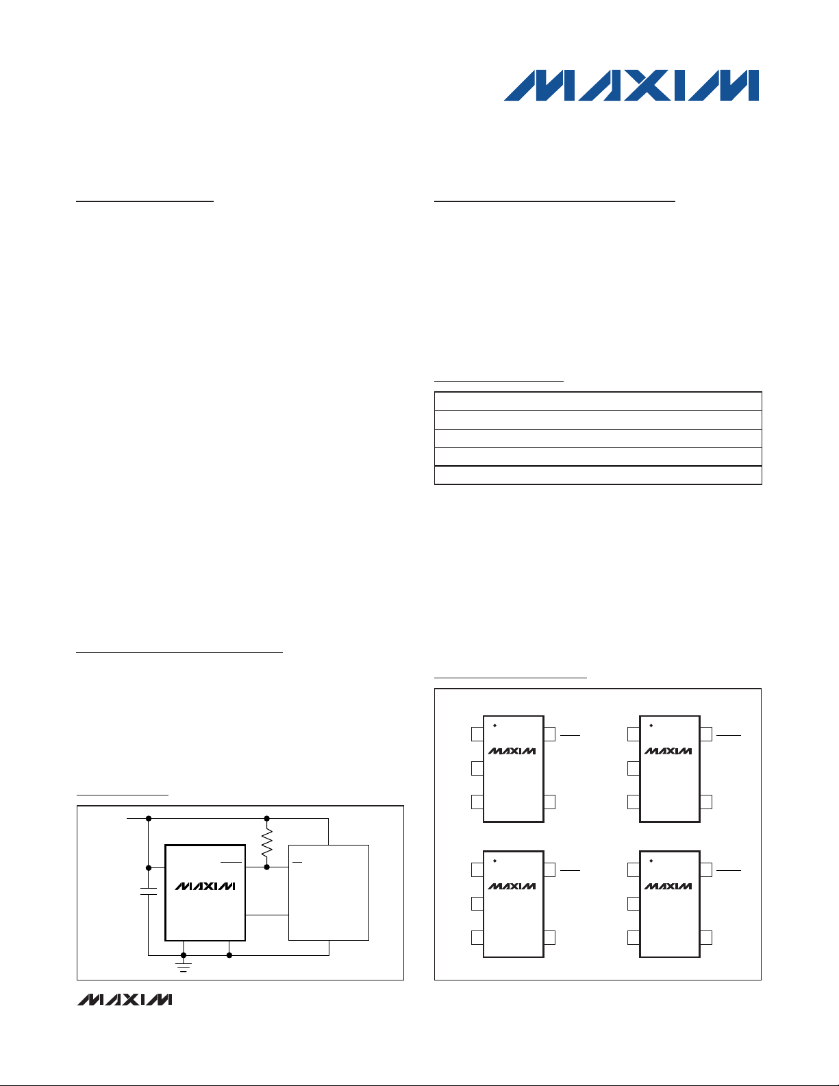
Ordering Information
MAX6517
V
CC
GND
MICROCONTROLLER
INT
ADC IN
V
CC
V
CC
GND HYST
OUT
TOVER
0.1μF
100kΩ
Typical Operating Circuit
19-3007; Rev 1; 2/11
For pricing, delivery, and ordering information, please contact Maxim Direct at 1-888-629-4642,
or visit Maxim’s website at www.maxim-ic.com.
Pin Configurations
Fan Control
Test Equipment
Temperature Control
Temperature Alarms
Over/Undertemperature
Protection
Notebook, Desktop PCs
RAID
Servers
Note: These parts are offered in 16 standard temperature versions with a minimum order of 2500 pieces. To complete the
suffix information, add P or N for positive or negative trip temperature, and select an available trip point in degrees centigrade. For example, the MAX6516UKP065+T describes a
MAX6516 in a 5-pin SOT23 package with a +65°C threshold.
Contact the factory for pricing and availability.
+
Denotes a lead(Pb)-free/RoHS-compliant package.
T = Tape and reel.
Functional Diagram appears at end of data sheet.
PART TEMP RANGE PIN-PACKAGE
MAX6516UK _ _ _ _ +T -55°C to +125°C 5 SOT23
MAX6517UK _ _ _ _ +T -55°C to +125°C 5 SOT23
MAX6518UK _ _ _ _ +T -55°C to +125°C 5 SOT23
MAX6519UK _ _ _ _ +T -55°C to +125°C 5 SOT23
TOP VIEW
GND
15OUT
2
(MAX6516)
MAX6517
(TOVER)
TOVER
GND
15OUT
2
(MAX6516)
MAX6517
(TUNDER)
TUNDER
HYST
34
SOT23
15HYST
(MAX6518)
2
GND
OUT
MAX6519
34
SOT23
V
CC
(TOVER)
TOVER
V
CC
HYST
34
SOT23
15HYST
(MAX6518)
2
GND
OUT
MAX6519
34
SOT23
V
CC
(TUNDER)
TUNDER
V
CC
Page 2

MAX6516–MAX6519
Low-Cost, 2.7V to 5.5V, Analog Temperature
Sensor Switches in a SOT23
2 _______________________________________________________________________________________
ABSOLUTE MAXIMUM RATINGS
ELECTRICAL CHARACTERISTICS
(VCC= 2.7V to 5.5V, R
PULLUP
= 100kΩ (open-drain output only), TA= -55°C to +125°C, unless otherwise noted. Typical values are at
T
A
= +25°C.) (Note 1)
Stresses beyond those listed under “Absolute Maximum Ratings” may cause permanent damage to the device. These are stress ratings only, and functional
operation of the device at these or any other conditions beyond those indicated in the operational sections of the specifications is not implied. Exposure to
absolute maximum rating conditions for extended periods may affect device reliability.
Note 1: 100% production tested at TA= +25°C. Specifications over temperature are guaranteed by design.
Note 2: The MAX6516–MAX6519 are available with internal factory-programmed temperature trip thresholds from -45°C to +115°C
in 10°C increments.
Note 3: V
CC
must be greater than 4.5V for a switching threshold of -45°C.
Note 4: Guaranteed by design.
All voltages are referenced to GND.
V
CC
...........................................................................-0.3V to +6V
TOVER, TUNDER (open drain)................................ -0.3V to +6V
TOVER, TUNDER (push-pull) .................... -0.3V to (V
CC
+ 0.3V)
OUT, HYST .................................................-0.3V to (V
CC
+ 0.3V)
OUT Short to GND .........................................................Indefinite
Continuous Power Dissipation (T
A
= +70°C)
SOT23 (derate 3.1mW/°C above +70°C).....................247mW
Operating Temperature Range ........................-55°C to +125°C
Junction Temperature..................................................... +150°C
Storage Temperature Range .............................-65°C to +150°C
Lead Temperature (soldering, 10s) ................................ +300°C
Soldering Temperature (reflow) .......................................+260°C
Supply Voltage Range V
Supply Current I
Temperature Threshold Accuracy
(Note 2)
Temperature Threshold
Hysteresis
HYST Input Logic Level (Note 4)
Logic Output Voltage High
(Push-Pull)
Logic Output Voltage Low
(Push-Pull and Open Drain)
Open-Drain Output Leakage
Current
OUT TEMPERATURE SENSITIVITY
Error to Equation:
OUT = 1.8015V - 10.62mV(T - 30)
- 1.1µV (T - 30)
Sensor Gain -10.62 mV/°C
OUT Capacitive Load (Note 4) 1000 pF
OUT Load Regulation
OUT Line Regulation 0.04 0.3 °C/V
PARAMETER SYMBOL CONDITIONS MIN TYP MAX UNITS
2
CC
Hot-temperature thresholds
(+35°C to +115°C)
Cold-temperature thresholds
(-45°C to +15°C)
-15°C to +65°C -1.5 +1.5
+75°C to +115°C -2.5 +2.5
TH
-45°C to -25°C (Note 3) -3 +3
HYST = V
HYST = GND 10
IH
IL
I
SOURCE
I
SOURCE
I
SINK
I
SINK
V
CC
-30°C to +125°C, VCC = 2.7V to 5.5V -2 +2
-55°C to -30°C (Note 3) -5 +2
0 < I
-1µA < I
CC
= 500µA, V
= 800µA, V
= 1.2mA, V
= 3.2mA, V
= 2.7V, open-drain output = 5.5V 10 nA
< 40µA 0.24
OUT
< 0 0.02
OUT
> 2.7V 0.8 x V
CC
> 4.5V VCC - 1.5
CC
> 2.7V 0.3
CC
> 4.5V 0.4
CC
ΔT
T
HYST
V
V
V
CC
V
OH
OL
2.7 5.5 V
22 40
40
2
0.8 x V
CC
0.2 x V
CC
CC
µA
°C
°C
V
V
V
°C
°C
Page 3
MAX6516–MAX6519
Low-Cost, 2.7V to 5.5V, Analog Temperature
Sensor Switches in a SOT23
_______________________________________________________________________________________
3
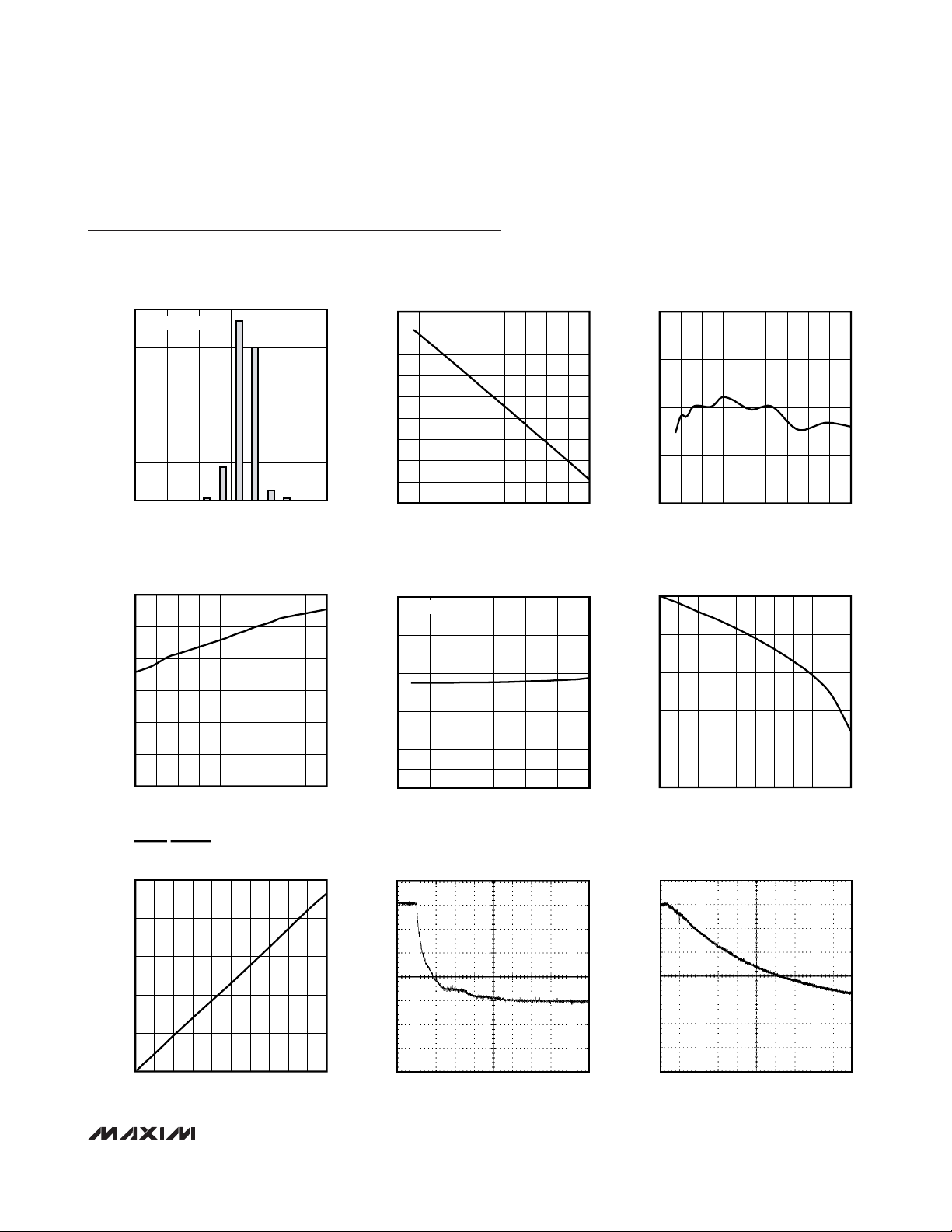
Typical Operating Characteristics
(VCC= 5V, TA = +25°C, unless otherwise noted.)
TRIP-THRESHOLD ACCURACY
50
SAMPLE SIZE = 147
1.0
TO 1.25
MAX6516 toc01
40
30
20
10
PERCENTAGE OF PARTS SAMPLED (%)
0
-1.25
TO -1.5
-0.75
TO -1.0
-0.25
TO 0.25
TO -0.5
ACCURACY (°C)
0.5
0
TO 0.75
SUPPLY CURRENT vs. TEMPERATURE
30
25
20
15
10
SUPPLY CURRENT (μA)
5
0
-55 125
TEMPERATURE (°C)
MAX6516 toc04
105856545255-15-35
OUTPUT VOLTAGE vs. TEMPERATURE
2.75
2.50
2.25
2.00
1.75
(V)
OUT
V
1.50
1.25
1.00
0.75
0.50
-55 125
TEMPERATURE (°C)
OUTPUT VOLTAGE vs. SUPPLY VOLTAGE
1.8300
TA = +30°C
1.8250
1.8200
1.8150
1.8100
(V)
1.8050
OUT
V
1.8000
1.7950
1.7900
1.7850
1.7800
2.5 5.5
SUPPLY VOLTAGE (V)
TEMPERATURE ERROR
2
MAX6516 toc02
1058545 65-15 5 25-35
1
0
TEMPERATURE ERROR (°C)
-1
-2
-55 125
TOVER/TUNDER OUTPUT VOLTAGE HIGH
5
MAX6516 toc05
5.04.54.03.53.0
4
3
(V)
OH
V
2
1
0
010
vs. TEMPERATURE
TEMPERATURE (°C)
vs. SOURCE CURRENT
I
(mA)
SINK
MAX6516 toc03
105856545255-15-35
MAX6516 toc06
987654321
TOVER/TUNDER OUTPUT VOLTAGE LOW
vs. SOURCE CURRENT
500
+25°C
400
300
(V)
OL
V
200
100
0
010
I
(mA)
SINK
MAX6516 toc07
987654321
THERMAL STEP RESPONSE IN
PERFLOURINATED FLUID
2s/div
MAX6516 toc08
+25°C
+18.5°C/div
+100°C
THERMAL STEP RESPONSE IN
STILL AIR
10s/div
MAX6516 toc09
+18.5°C/div
+100°C
Page 4
MAX6516–MAX6519
Low-Cost, 2.7V to 5.5V, Analog Temperature
Sensor Switches in a SOT23
4 _______________________________________________________________________________________
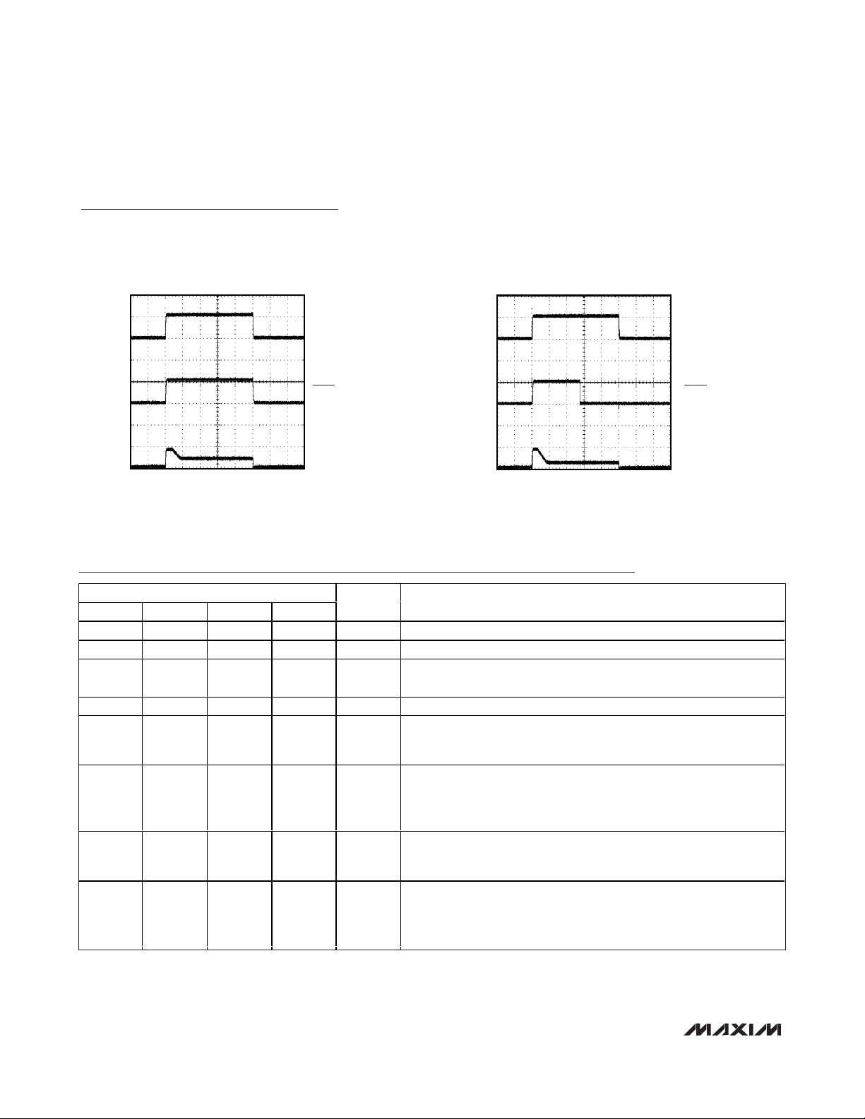
Pin Description
STARTUP AND POWER-DOWN
(TEMP < T
TH
)
MAX6516 toc10
VCC (5V/div)
TOVER (5V/div)
V
OUT
(5V/div)
200μs/div
MAX6516 toc11
STARTUP DELAY
(TEMP > T
TH
)
VCC (5V/div)
TOVER (5V/div)
V
OUT
(5V/div)
200μs/div
Typical Operating Characteristics (continued)
(VCC= 5V, TA = +25°C, unless otherwise noted.)
PIN
MAX6516 MAX6517 MAX6518 MAX6519
1 1 3 3 OUT Analog Output. Voltage represents the die’s temperature.
2 2 2 2 GND Ground
3 3 1 1 HYST
4444VCCInput Supply. Bypass to ground with a 0.1µF capacitor.
5 — 5 — TOVER
—5—5TOVER
5 — 5 — TUNDER
—5—5TUNDER
NAME FUNCTION
Hysteresis Input. Connect to V
10°C hysteresis.
Push-Pull Active-High Output (Hot Threshold). TOVER goes high when
the die temperature exceeds the factory-programmed hot temperature
threshold.
Open-Drain, Active-Low Output (Hot Threshold). TOVER goes low
when the die temperature exceeds the factory-programmed hot
temperature threshold. Connect to a 100kΩ pullup resistor. May be
pulled up to a voltage higher than V
Push-Pull Active-High Output (Cold Threshold). TUNDER goes high
when the die temperature falls below the factory-programmed cold
temperature threshold.
Open-Drain, Active-Low Output (Cold Threshold). TUNDER goes low
when the die temperature goes below the factory-programmed cold
temperature threshold. Connect to a 100kΩ pullup resistor. May be
pulled up to a voltage higher than V
for 2°C of hysteresis or to GND for
CC
.
CC
.
CC
Page 5

Detailed Description
The MAX6516–MAX6519 fully integrated temperature
switches incorporate a fixed reference, an analog temperature sensor, and a comparator. The temperature at
which the two reference voltages are equal determines
the temperature trip point. OUT is an analog voltage
that varies with the die’s temperature. Pin-selectable
2°C or 10°C hysteresis keeps the digital output from
oscillating when the die temperature approaches the
threshold temperature. The MAX6516 and MAX6518
have an active-high, push-pull output structure that can
sink or source current. The MAX6517 and MAX6519
have an active-low, open-drain output structure that
can only sink current. The internal power-on reset circuit guarantees the logic output is at its +25°C state for
at least 50µs.
Analog Output
OUT is an analog output that is proportional to the die
temperature. OUT voltage range is between 0.77V to
2.59V, within the temperature range of -45°C to
+125°C. For applications with a switching threshold of
-45°C, the supply voltage must be greater than 4.5V.
The temperature-to-voltage transfer function is approximately linear and can be described by the quadratic
equation:
V
OUT
= 1.8015 - 10.62mV (T - 30) + 1.1µV (T - 30)
2
where T = temperature in °C.
In most cases, a linear approximation can be applied:
V
OUT
= 1.8015 - 10.62mV (T - 30)
Therefore,
Hysteresis Input
The HYST input selects the devices’ temperature hysteresis and prevents the output from oscillating when the
temperature approaches the trip point. Connect HYST to
VCCfor 2°C hysteresis or to GND for 10°C hysteresis.
Logic Temperature Indicators
Overtemperature Indicator (Hot Thresholds)
TOVER and TOVER designations apply to thresholds
above TA= +25°C (+35°C, +45°C, +55°C, +65°C, +75°C,
+85°C, +95°C, +105°C, +115°C). All “hot” thresholds are
positive temperatures.
The overtemperature indicator output is open-drain
active low (TOVER) or push-pull active high (TOVER).
TOVER goes low when the die temperature exceeds
the factory-programmed temperature threshold. TOVER
should be pulled up to a voltage no greater than 5.5V
with a 100kΩ pullup resistor. TOVER is a push-pull
active-high CMOS output that goes high when the die
temperature exceeds the factory-programmed temperature threshold.
Undertemperature Indicator (Cold Thresholds)
TUNDER and TUNDER designations apply to thresholds
below TA= +25°C (+15°C, +5°C, -5°C, -15°C, -25°C,
-35°C, -45°C). The undertemperature indicator output is
open drain, active low (TUNDER), or push-pull active
high (TUNDER). TUNDER goes low when the die temperature goes below the factory-programmed temperature threshold. TUNDER should be pulled up to a
voltage no greater than 5.5V with a 100kΩ pullup resistor. TUNDER is a push-pull active-high CMOS output
that goes high when the die temperature falls below the
factory-programmed temperature threshold.
Applications Information
Temperature-Window Alarm
The MAX6516/MAX6518 logic outputs assert when the
die temperature is outside the factory-programmed
range. Combining the outputs of two devices creates
an over/undertemperature alarm. Two MAX6516s or
two MAX6518s are used to form two complementary
pairs, containing one cold trip-point output and one hot
trip-point output. The assertion of either output alerts
the system to an out-of-range temperature. The
MAX6516 push-pull output stages can be ORed to
produce a thermal out-of-range alarm (Figure 1).
More favorably, two MAX6517s or two MAX6519s can
be directly wire-ORed with a single external resistor to
accomplish the same task. The temperature window
alarms shown in Figure 2 can be used to accurately
determine when a device’s temperature falls out of the
-5°C to +75°C range. The thermal overrange signal can
be used to assert a thermal shutdown, power-up,
recalibration, or other temperature-dependent function.
MAX6516–MAX6519
Low-Cost, 2.7V to 5.5V, Analog Temperature
Sensor Switches in a SOT23
_______________________________________________________________________________________ 5
V
−1 8015
.
T
=+°
0 01062
.
OUT
30
C
Page 6
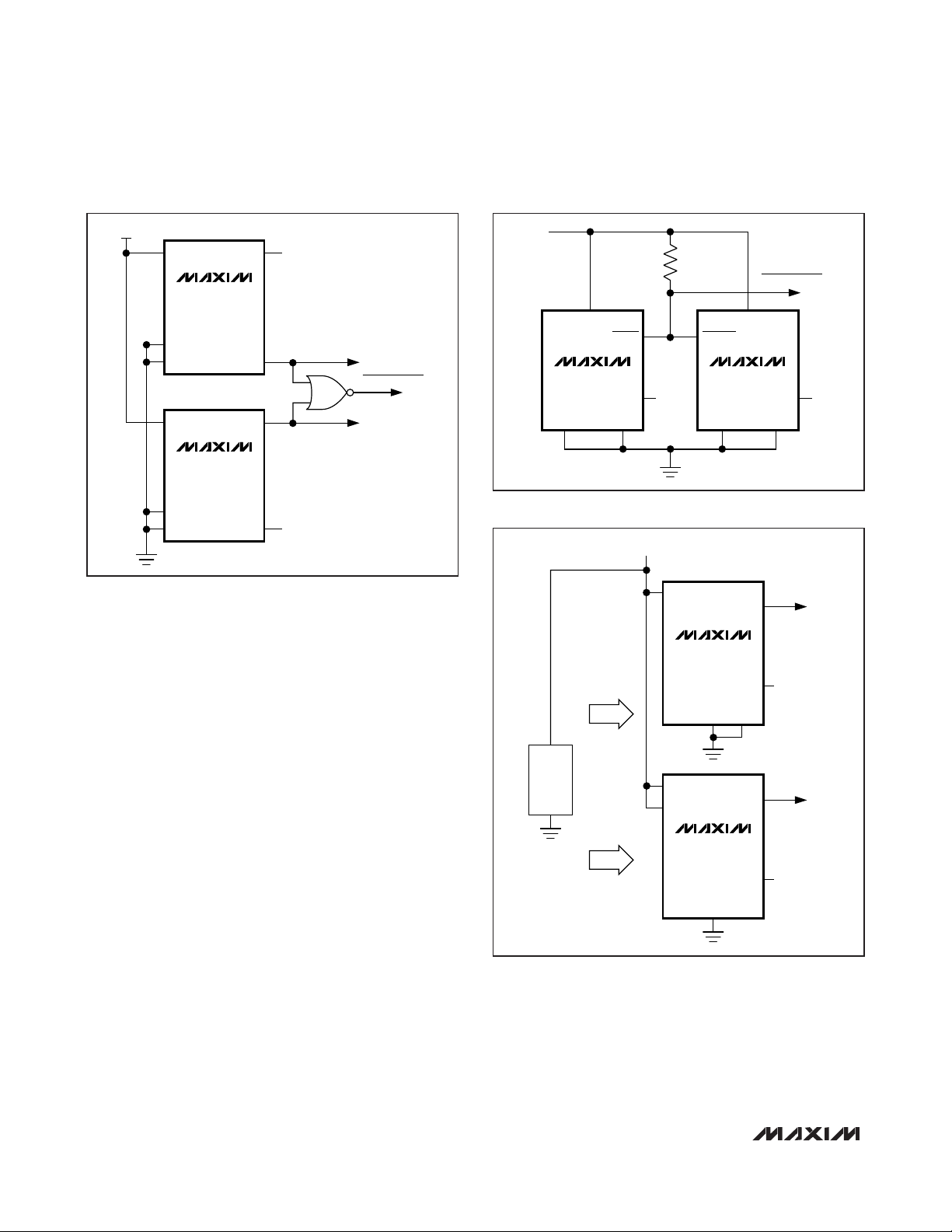
MAX6516–MAX6519
Low-Cost, Fail-Safe Temperature
In high-performance/high-reliability applications, multiple temperature monitoring is important. The high-level
integration and low cost of the MAX6516 and MAX6518
facilitate the use of multiple temperature monitors to
increase system reliability. The application in Figure 3
uses two MAX6516s with different hot temperature
thresholds to ensure that fault conditions that can
overheat the monitored device cause no permanent
damage. The first temperature monitor activates the fan
when the die temperature exceeds +45°C. The second
MAX6516 triggers a system shutdown if the die
temperature reaches +75°C, preventing damage from
a wide variety of destructive fault conditions, including
latchups, short circuits, and cooling-system failures.
PC Board Testing
The MAX6516–MAX6519 temp sensor devices can be
tested after PC board assembly using OUT. Testing
can be used to verify proper assembly and functionality
of the temperature protection circuitry. Since OUT has
a weak drive capability, the voltage at OUT can be
forced to cause the digital outputs to change states,
thereby verifying that the internal comparators and output circuitry function properly after assembly. Below is
a test procedure that can be used to test the
MAX6516–MAX6519:
• Power up the device, measure OUT, and observe the
state of the logic output.
Low-Cost, 2.7V to 5.5V, Analog Temperature
Sensor Switches in a SOT23
6 _______________________________________________________________________________________
Figure 1. Temperature-Window Alarms Using the MAX6516
Figure 2. Temperature Window Alarm Using the MAX6517
Figure 3. Low-Power, High-Reliability, Fail-Safe Temperature
Monitor
5V
V
CC
MAX6516UKP075
GND
HYST
V
CC
MAX6516UKN005
GND
HYST
OUT
TOVER
TUNDER
OUT
OVERTEMP
OUT OF RANGE
UNDERTEMP
5V
100kΩ
OUT OF RANGE
V
CC
TOVER
MAX6517UKP075 MAX6517UKN005
OUT
GND HYST HYST
TUNDER
GND
V
CC
OUT
SYSTEM
SHUTDOWN
OUT
FAN CONTROL
OUT
μP
GND
HEAT
HEAT
V
CC
MAX6516UKP075
GND5VHYST
V
CC
HYST
MAX6516UKP045
GND
TOVER
TOVER
Page 7

• Calculate the temperature using the formula:
• Verify that the temperature measured is within ±2°C
of the ambient board temperature. Measure the
ambient board temperature using an accurate calibrated temperature sensor.
• Connect OUT to ground (OUT to VCCfor cold
threshold versions) and observe the state change of
the logic output.
• Disconnect OUT from ground and observe that the
logic output reverts to its initial state.
Hysteresis Testing
The MAX6516–MAX6519 can be programmed with 2°C
or 10°C of hysteresis by pin strapping HYST to VCCor
GND, respectively. Below is a test feature that can be
used to measure the accuracy of the device’s hysteresis using a device with a +65°C threshold:
• Power up the device and observe the state of the
digital output.
• Drive the OUT voltage down gradually.
• When the digital output changes state, note V
OUT
.
•V
OUT
trip = V
OUT
at logic output change of state
(high to low or low to high).
• Calculate trip temperature (T1) using:
• Gradually raise V
OUT
until the digital output reverts to
its initial state and note V
OUT
.
• Calculate trip temperature (T2).
•T
HYST
= T2 - T1.
Thermal Considerations
The MAX6516–MAX6519 supply current is typically 22µA.
When used to drive high-impedance loads, the devices
dissipate negligible power. Therefore, the die temperature is essentially the same as the package temperature.
Accurate temperature monitoring depends on the thermal
resistance between the device being monitored and the
MAX6516–MAX6519 die. Heat flows in and out of plastic
packages, primarily through the leads. Pin 2 of the 5-pin
SOT23 package provides the lowest thermal resistance to
the die. Short, wide copper traces between the
MAX6516–MAX6519 and the object whose temperature
is being monitored ensures heat transfers occur quickly
and reliably. The rise in die temperature due to self-heating is given by the following formula:
ΔT
J
= P
DISSIPATION
✕ θ
JA
where P
DISSIPATION
is the power dissipated by the
MAX6516–MAX6519, and θJAis the thermal resistance
of the package.
The typical thermal resistance is 140°C/W for the
5-pin SOT23 package. To limit the effects of selfheating, minimize the output current. For example, if the
MAX6516–MAX6519 sink 1mA, the open-drain output
voltage is guaranteed to be less than 0.3V. Therefore,
an additional 0.3mW of power is dissipated within the
IC. This corresponds to a 0.042°C shift in the die temperature in the 5-pin SOT23 package.
Chip Information
PROCESS: BiCMOS
MAX6516–MAX6519
Low-Cost, 2.7V to 5.5V, Analog Temperature
Sensor Switches in a SOT23
_______________________________________________________________________________________ 7
V
−1 8015
.
T
=+
0 01062
.
OUT
30
.
T
=+
0 01062
.
V
−1 8015
OUT
30
Page 8

MAX6516–MAX6519
Low-Cost, 2.7V to 5.5V, Analog Temperature
Sensor Switches in a SOT23
8 _______________________________________________________________________________________
Table 1. Top Marks
Package Information
For the latest package outline information and land patterns
(footprints), go to www.maxim-ic.com/packages
. Note that a
“+”, “#”, or “-” in the package code indicates RoHS status only.
Package drawings may show a different suffix character, but
the drawing pertains to the package regardless of RoHS status.
PACKAGE
TYPE
PACKAGE
CODE
OUTLINE
NO.
LAND
PATTERN NO.
5 SOT23 U5+2
21-0057 90-0174
PART
MAX6516UKN045 AEHS MAX6518UKN045 AELL
MAX6516UKN035 AECZ MAX6518UKN035 AEDD
MAX6516UKN025 AEHR MAX6518UKN025 AELK
MAX6516UKN015 AEHQ MAX6518UKN015 AELJ
MAX6516UKN005 AEHP MAX6518UKN005 AELI
MAX6516UKP005 AEHT MAX6518UKP005 AELM
MAX6516UKP015 AEHU MAX6518UKP015 AELN
MAX6516UKP035 AEHV MAX6518UKP035 AELO
MAX6516UKP045 AEHW MAX6518UKP045 AELP
MAX6516UKP055 AEHX MAX6518UKP055 AELQ
MAX6516UKP065 AEHY MAX6518UKP065 AELR
MAX6516UKP075 AEDA MAX6518UKP075 AEDE
MAX6516UKP085 AEHZ MAX6518UKP085 AELS
MAX6516UKP095 AEIA MAX6518UKP095 AELT
MAX6516UKP105 AEIB MAX6518UKP105 AELU
MAX6516UKP115 AEIC MAX6518UKP115 AELV
MAX6517UKN045 AELZ MAX6519UKN045 AEIG
MAX6517UKN035 AEDB MAX6519UKN035 AEDF
MAX6517UKN025 AELY MAX6519UKN025 AEIF
MAX6517UKN015 AELX MAX6519UKN015 AEIE
MAX6517UKN005 AELW MAX6519UKN005 AEID
MAX6517UKP005 AEMA MAX6519UKP005 AEIH
MAX6517UKP015 AEMB MAX6519UKP015 AEII
MAX6517UKP035 AEMC MAX6519UKP035 AEIS
MAX6517UKP045 AEMD MAX6519UKP045 AEIK
MAX6517UKP055 AEME MAX6519UKP055 AEIL
MAX6517UKP065 AEMF MAX6519UKP065 AEIM
MAX6517UKP075 AEDC MAX6519UKP075 AEDG
MAX6517UKP085 AEMG MAX6519UKP085 AEIN
MAX6517UKP095 AEMH MAX6519UKP095 AEIO
MAX6517UKP105 AEMI MAX6519UKP105 AEIP
MAX6517UKP115 AEMJ MAX6519UKP115 AEIQ
TOP
MARK
PART
TOP
MARK
Page 9
MAX6516–MAX6519
Low-Cost, 2.7V to 5.5V, Analog Temperature
Sensor Switches in a SOT23
_______________________________________________________________________________________ 9
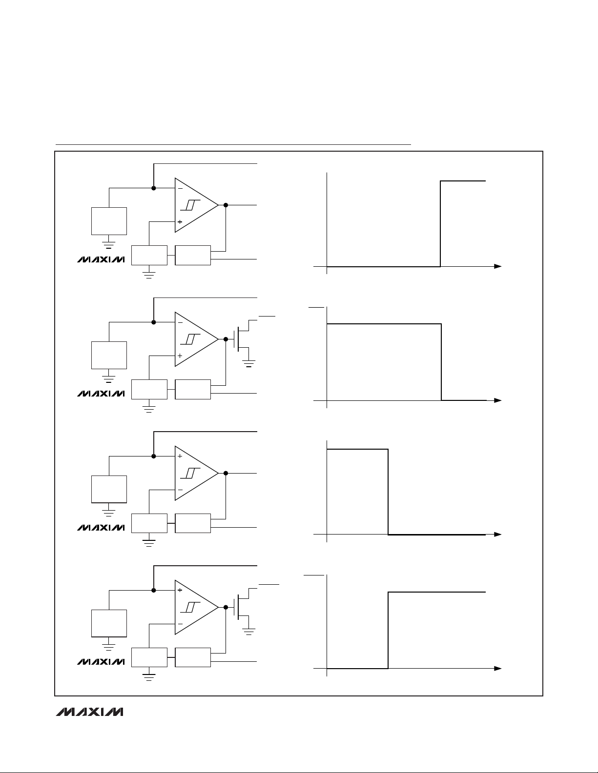
Functional Diagram
NEGATIVE
TEMPCO
REFERENCE
MAX6516/
MAX6518
NEGATIVE
TEMPCO
REFERENCE
MAX6517/
MAX6519
FIXED
REFERENCE
FIXED
REFERENCE
HYST
NETWORK
HYST
NETWORK
OUT
TOVER
HYST
OUT
TOVER
HYST
V
TOVER
TOVER
MAX6516/MAX6518 (HOT THRESHOLD)
COLD +25°CTTHHOT
V
COLD +25°CTTHHOT
MAX6517/MAX6519 (HOT THRESHOLD)
WITH 100kΩ PULLUP
TEMP
TEMP
NEGATIVE
TEMPCO
REFERENCE
MAX6516/
MAX6518
NEGATIVE
TEMPCO
REFERENCE
MAX6517/
MAX6519
FIXED
REFERENCE
FIXED
REFERENCE
HYST
NETWORK
HYST
NETWORK
OUT
TUNDER
HYST
OUT
TUNDER
HYST
V
TUNDER
COLD T
V
TUNDER
COLD T
MAX6516/MAX6518 (COLD THRESHOLD)
TH
MAX6517/MAX6519 (COLD THRESHOLD)
WITH 100kΩ PULLUP
TH
+25°C HOT
+25°C HOT
TEMP
TEMP
Page 10

MAX6516–MAX6519
Low-Cost, 2.7V to 5.5V, Analog Temperature
Sensor Switches in a SOT23
Maxim cannot assume responsibility for use of any circuitry other than circuitry entirely embodied in a Maxim product. No circuit patent licenses are
implied. Maxim reserves the right to change the circuitry and specifications without notice at any time.
10
____________________Maxim Integrated Products, 120 San Gabriel Drive, Sunnyvale, CA 94086 408-737-7600
© 2011 Maxim Integrated Products Maxim is a registered trademark of Maxim Integrated Products, Inc.
Revision History
REVISION
NUMBER
0 11/03 Initial release —
1 2/11
REVISION
DATE
DESCRIPTION
Changed the leaded parts to lead(Pb)-free parts in the Ordering Information table; in
the Absolute Maximum Ratings section changed the continuous power diss ipation
numbers (7.1mW/°C to 3.1mW/°C and 571mW to 247mW); added the Package
Informat ion table
PAGES
CHANGED
1, 2, 8
 Loading...