

Page 1
General Description
The MAX6514/MAX6515 low-cost, fully integrated temperature switches assert a logic signal when their die temperature crosses a factory-programmed threshold.
Operating from a 2.7V to 5.5V supply, these devices feature a fixed voltage reference, an analog temperature
sensor, and a comparator. They are available with factory-trimmed temperature trip thresholds from -45°C to
+15°C and +35°C to +115°C in 10°C increments, and are
accurate to ±1°C (typ). These devices require no external
components and typically consume 22µA of supply current. Hysteresis is pin selectable at 2°C or 10°C.
The MAX6514/MAX6515 are offered with hot-temperature thresholds (+35°C to +115°C), asserting when the
temperature is above the threshold or with cold-temperature thresholds (-45°C to +15°C), asserting when the
temperature is below the threshold. The MAX6514/
MAX6515 can be used over a -35°C to +125°C range
with a supply voltage of 2.7V to 5.5V. For applications
sensing temperature down to -45°C, a supply voltage
above 4.5V is required.
The MAX6514 has an active-high, push-pull output. The
MAX6515 has an active-low, open-drain output. These
devices are available in a space-saving 5-pin SOT23
package and operate over the -55°C to +125°C temperature range.
Applications
Over/Undertemperature Protection
Fan Control
Test Equipment
Temperature Control
Temperature Alarms
Notebook, Desktop PCs
RAID
Servers
Features
♦ High-Accuracy ±1.5°C (max) over -15°C to +65°C
Temperature Range
♦ Low-Power Consumption: 22µA Typical Current
♦ Factory-Programmed Thresholds from -45°C to
+115°C in 10°C Increments
♦ Open-Drain or Push-Pull Outputs
♦ Pin-Selectable 2°C or 10°C Hysteresis
MAX6514/MAX6515
Low-Cost, 2.7V to 5.5V Temperature Switches
in a SOT23
________________________________________________________________
Maxim Integrated Products
1
Ordering Information
19-3147; Rev 1; 2/11
For pricing, delivery, and ordering information, please contact Maxim Direct at 1-888-629-4642,
or visit Maxim’s website at www.maxim-ic.com.
Pin Configurations and Functional Diagram appear at end of
data sheet.
Note: These parts are offered in 16 standard temperature ver-
sions with a minimum order of 2500 pieces. To complete the
suffix information, add P or N for positive or negative trip temperature, and select an available trip point in degrees centigrade. For example, the MAX6514UKP065+T describes a
MAX6514 in a 5-pin SOT23 package with a +65°C threshold in
tape and reel (2.5k minimum order). Contact the factory for
pricing and availability.
+
Denotes a lead(Pb)-free/RoHS-compliant package.
T = Tape and reel.
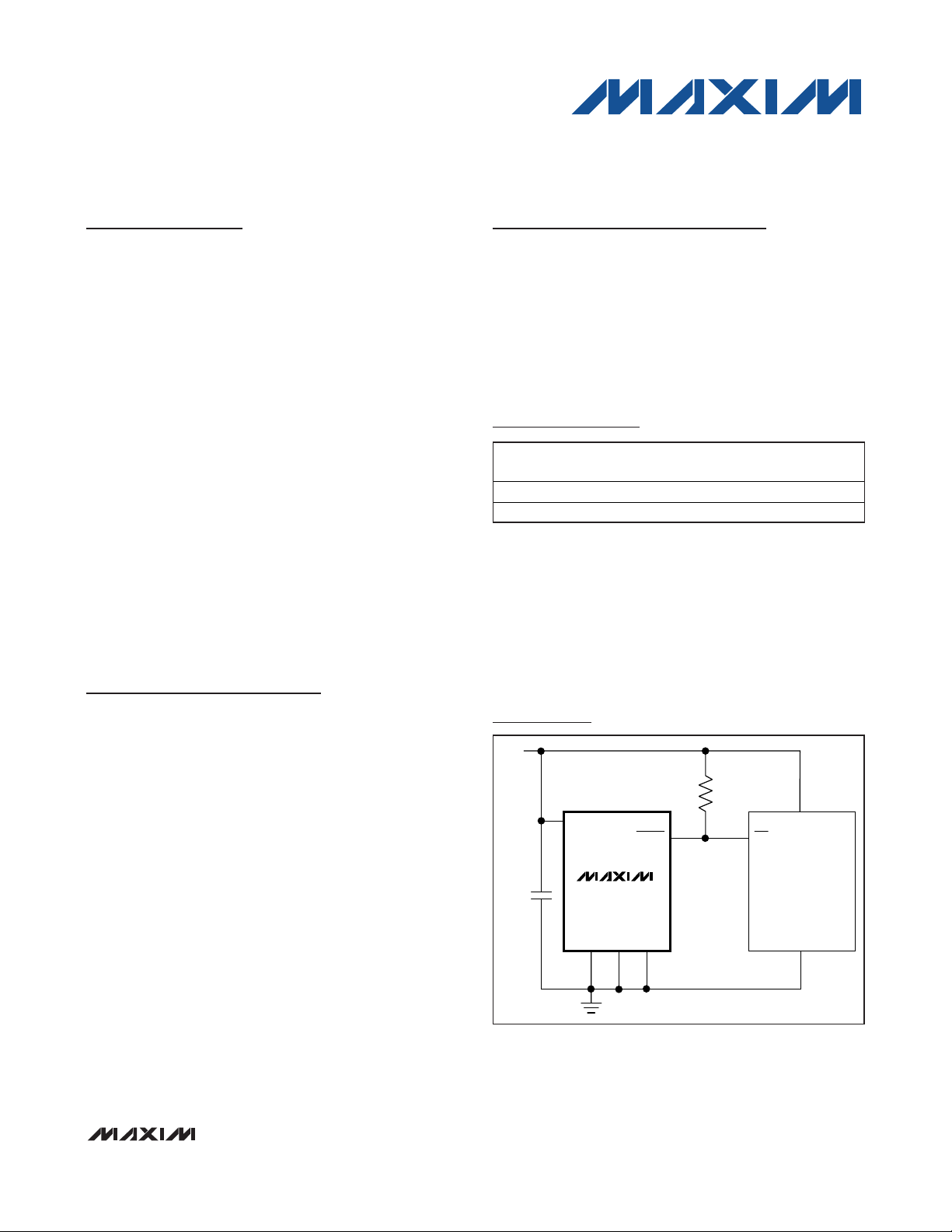
Typical Operating Circuit
PART TEMP RANGE
MAX6514UK_ _ _ _ +T -55°C to +125°C 5 SOT23
MAX6515UK_ _ _ _ +T -55°C to +125°C 5 SOT23
PINPACKAGE
V
CC
100kΩ
0.1μF
V
CC
TOVER
MAX6515
V
CC
INT
MICROCONTROLLER
GND
GND HYST
GND
Page 2
MAX6514/MAX6515
Low-Cost, 2.7V to 5.5V Temperature Switches
in a SOT23
2 _______________________________________________________________________________________
ABSOLUTE MAXIMUM RATINGS
ELECTRICAL CHARACTERISTICS
(V
CC
= 2.7V to 5.5V, R
PULLUP
= 100kΩ, (open-drain output only), TA= -55°C to +125°C, unless otherwise noted. Typical values are
at T
A
= +25°C.) (Note 1)
Stresses beyond those listed under “Absolute Maximum Ratings” may cause permanent damage to the device. These are stress ratings only, and functional
operation of the device at these or any other conditions beyond those indicated in the operational sections of the specifications is not implied. Exposure to
absolute maximum rating conditions for extended periods may affect device reliability.
Note 1: 100% production tested at TA = +25°C. Specifications over temperature are guaranteed by design.
Note 2: The MAX6514/MAX6515 are available with internal factory-programmed temperature trip thresholds from -45°C to +15°C
and +35°C to +115°C in 10°C increments.
Note 3: V
CC
must be greater than 4.5V for a switching threshold of -45°C.
Note 4: Guaranteed by design.
All Voltages Are Referenced to GND
V
CC
..........................................................................-0.3V to +6V
TOVER, TUNDER (open drain)................................ -0.3V to +6V
TOVER, TUNDER (push-pull)....................... -0.3V to V
CC
+ 0.3V
HYST.............................................................-0.3V to V
CC
+ 0.3V
Continuous Power Dissipation
SOT23 (derate 3.1mW/°C above +70°C).....................247mW
Operating Temperature Range ........................-55°C to +125°C
Junction Temperature..................................................... +150°C
Storage Temperature Range .............................-65°C to +150°C
Lead Temperature (soldering, 10s) ................................ +300°C
Soldering Temperature ....................................................+260°C
PARAMETER SYMBOL CONDITIONS MIN TYP MAX UNITS
Supply Voltage Range V
Supply Current I
Temperature Threshold Accuracy
(Note 2)
Temperature Threshold
Hysteresis
HYST Input Threshold (Note 4)
Logic Output Voltage High
(Push-Pull)
Logic Output Voltage Low
(Push-Pull and Open Drain)
Open-Drain Output Leakage
Current
CC
Hot-temperature thresholds
(+35°C to +115°C)
Cold-temperature thresholds
(-45°C to +15°C)
-15°C to +65°C -1.5 +1.5
+75°C to +115°C -2.5 +2.5
TH
-45°C to -25°C (Note 3) -3 +3
HYST = V
HYST = GND 10
IH
IL
I
SOURCE
I
SOURCE
I
SINK
I
SINK
V
CC
CC
= 500µA, V
= 800µA, V
= 1.2mA, V
= 3.2mA, V
= 2.7V, open-drain output = 5.5V 10 nA
ΔT
T
V
CC
HYST
V
V
OH
V
OL
2.7 5.5 V
22 40
40
2
0.8 x V
CC
0.2 x V
CC
> 2.7V 0.8 x V
CC
> 4.5V VCC - 1.5
CC
> 2.7V 0.3
CC
> 4.5V 0.4
CC
CC
µA
°C
°C
V
V
V
Page 3
MAX6514/MAX6515
Low-Cost, 2.7V to 5.5V Temperature Switches
in a SOT23
_______________________________________________________________________________________
3
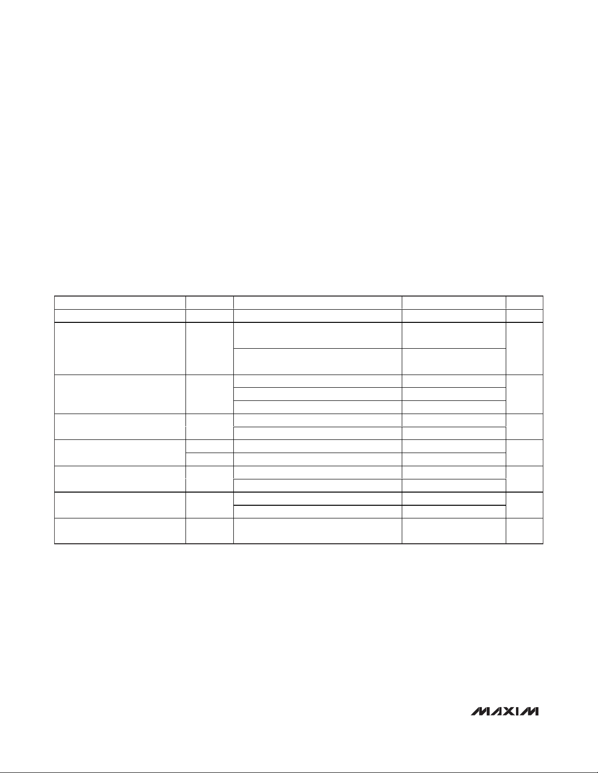
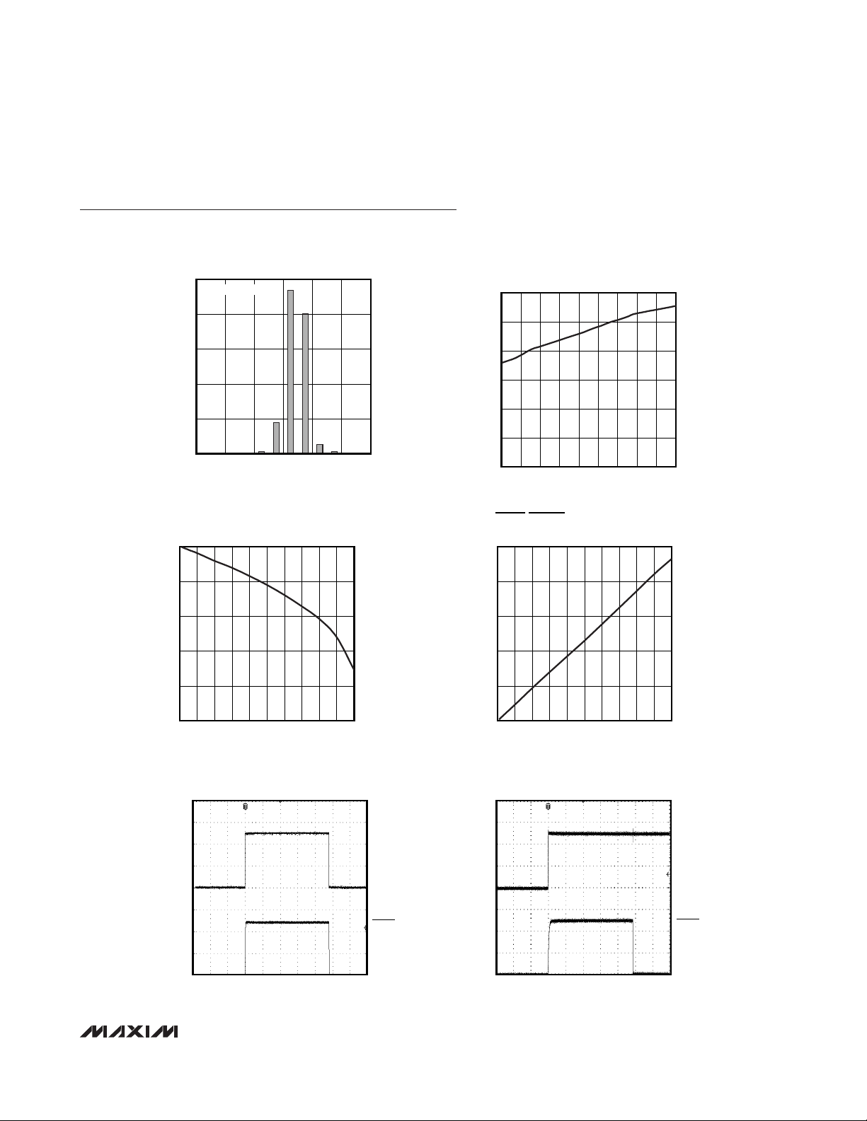
Typical Operating Characteristics
(VCC= 4.5V, TA = +25°C, unless otherwise noted.)
TRIP THRESHOLD ACCURACY
50
SAMPLE SIZE = 147
40
30
20
10
PERCENTAGE OF PARTS SAMPLED (%)
0
-1.25 TO
-1.5
-0.75 TO
-1.0
0.25 TO
-0.25 TO
-0.5
ACCURACY (°C)
0.75 TO
0.5
1.0
TOVER/TUNDER OUTPUT VOLTAGE HIGH
vs. SOURCE CURRENT
5
4
1.25 TO
1.5
MAX6514 toc03
MAX6514 toc01
SUPPLY CURRENT
30
25
20
15
10
SUPPLY CURRENT (μA)
5
0
-55 125
TOVER/TUNDER OUTPUT VOLTAGE LOW
500
400
vs. TEMPERATURE
MAX6514 toc02
105856545255-15-35
TEMPERATURE (°C)
vs. SINK CURRENT
MAX6514 toc04
3
(V)
OH
V
2
1
0
010
I
(mA)
SINK
STARTUP AND POWER-DOWN (TEMP < TTH)
TIME (400μs/div)
987654321
MAX6514 toc05
V
CC
(2V/div)
TOVER
(2V/div)
300
(V)
OL
V
200
100
0
010
I
(mA)
SINK
STARTUP DELAY (TEMP > TTH)
TIME = 100μs
987654321
MAX6514 toc06
V
CC
(2V/div)
TOVER
(2V/div)
Page 4

MAX6514/MAX6515
Low-Cost, 2.7V to 5.5V Temperature Switches
in a SOT23
4 _______________________________________________________________________________________
Pin Description
Detailed Description
The MAX6514/MAX6515 fully integrated temperature
switches incorporate a fixed reference, an analog temperature sensor, and a comparator. Pin-selectable 2°C
or 10°C hysteresis keeps the digital output from oscillating when the die temperature approaches the
threshold temperature. The MAX6514 has an activehigh, push-pull output structure that can sink or source
current. The MAX6515 has an active-low, open-drain
output structure that can only sink current. The internal
power-on reset circuit guarantees the logic output is at
its +25°C state for at least 50µs.
Hysteresis Input
The HYST input selects the devices’ temperature hysteresis and prevents the output from oscillating when the
temperature approaches the trip point. Connect HYST to
VCCfor 2°C hysteresis or to GND for 10°C hysteresis.
Logic Temperature Indicators
Overtemperature Indicator (Hot Thresholds)
TOVER and TOVER designations apply to thresholds
above TA= +25°C (+35°C, +45°C, +55°C, +65°C,
+75°C, +85°C, +95°C, +105°C, and +115°C). All “hot”
thresholds are positive temperatures.
The overtemperature indicator output is open drain
active low (TOVER) or push-pull active high (TOVER).
TOVER goes low when the die temperature exceeds
the factory-programmed temperature threshold. TOVER
should be pulled up to a voltage no greater than 5.5V
with a 100kΩ pullup resistor. TOVER is a push-pull
active-high CMOS output that goes high when the die
temperature exceeds the factory-programmed temperature threshold.
Undertemperature Indicator (Cold Thresholds)
TUNDER and TUNDER designations apply to thresholds below TA= +25°C (+15°C, +5°C, -5°C, -15°C,
-25°C, -35°C, -45°C). The undertemperature indicator
output is open-drain, active low (TUNDER) or push-pull,
active high (TUNDER). TUNDER goes low when the die
temperature goes below the factory-programmed temperature threshold. TUNDER should be pulled up to a
voltage no greater than 5.5V with a 100kΩ pullup resistor. TUNDER is a push-pull active-high CMOS output
that goes high when the die temperature falls below the
factory-programmed temperature threshold.
PIN
MAX6514 MAX6515
1, 2 1, 2 GND Ground
3 3 HYST Hysteresis Input. Connect to VCC for 2°C of hysteresis or to GND for 10°C hysteresis.
44VCCInput Supply. Bypass to ground with a 0.1µF capacitor.
5 — TOVER
—5TOVER
5 — TUNDER
—5TUNDER
NAME FUNCTION
Push-Pull Active-High Output (Hot Threshold). TOVER goes high when the die temperature
exceeds the factory-programmed hot-temperature threshold.
Open-Drain, Active-Low Output (Hot Threshold). TOVER goes low when the die temperature
exceeds the factory-programmed hot-temperature threshold. Connect to a 100kΩ pullup
resistor. Can be pulled up to a voltage higher than V
Push-Pull Active-High Output (Cold Threshold). TUNDER goes high when the die temperature
falls below the factory-programmed cold-temperature threshold.
Open-Drain, Active-Low Output (Cold Threshold). TUNDER goes low when the die
temperature goes below the factory-programmed cold-temperature threshold. Connect to a
100kΩ pullup resistor. Can be pulled up to a voltage higher than V
CC
.
.
CC
Page 5

Applications Information
Temperature-Window Alarm
The MAX6515 logic output asserts when the die temperature is outside the factory-programmed range.
Combining the outputs of two devices creates an
over/undertemperature alarm. Two MAX6515s are used
to form two complementary pairs, containing one cold
trip-point output and one hot trip-point output. The
assertion of either output alerts the system to an out-ofrange temperature (Figure 1).
The thermal overrange signal can be used to assert a
thermal shutdown, power-up, recalibration, or other
temperature-dependent function.
Low-Cost, Fail-Safe Temperature
In high-performance/high-reliability applications, multiple temperature monitoring is important. The high-level
integration and low cost of the MAX6514/MAX6515
facilitate the use of multiple temperature monitors to
increase system reliability. The Figure 2 application
uses two MAX6514s with different hot-temperature
thresholds to ensure that fault conditions that can overheat the monitored device cause no permanent damage. The first temperature monitor activates the fan
when the die temperature exceeds +45°C. The second
MAX6514 triggers a system shutdown if the die temperature reaches +75°C, preventing damage from a wide
variety of destructive fault conditions, including
latchups, short circuits, and cooling-system failures.
Thermal Considerations
The MAX6514/MAX6515 supply current is typically
22µA. When used to drive high-impedance loads, the
devices dissipate negligible power and self-heating
effects are minimized.
Accurate temperature monitoring depends on the thermal resistance between the device being monitored
and the MAX6514/MAX6515 die. Heat flows in and out
of plastic packages, primarily through the leads. Pin 2
of the 5-pin SOT23 package provides the lowest thermal resistance to the die. Short, wide copper traces
between the MAX6514/MAX6515 and the objects
whose temperature is being monitored ensure heat
transfers occur quickly and reliably. The rise in die temperature due to self-heating is given by the following
formula:
ΔTJ= P
DISSIPATION
x θ
JA
where P
DISSIPATION
is the power dissipated by the
MAX6514/MAX6515, and θJAis the thermal resistance
of the package.
The typical thermal resistance is +140°C/W for the 5pin SOT23 package. To limit the effects of self-heating,
minimize the output current. For example, if the
MAX6514/MAX6515 sink 1mA, the open-drain output
voltage is guaranteed to be less than 0.3V. Therefore,
an additional 0.3mW of power is dissipated within the
IC. This corresponds to a 0.042°C shift in the die temperature in the 5-pin SOT23 package.
MAX6514/MAX6515
Low-Cost, 2.7V to 5.5V Temperature Switches
in a SOT23
_______________________________________________________________________________________ 5
Figure 1. Temperature-Window Alarms Using the MAX6515
Figure 2. Low-Power, High-Reliability, Fail-Safe Temperature
Monitor
+5V
100kΩ
OUT OF RANGE
V
CC
TOVER
MAX6515UKP075
GND
GND HYST
+5V
V
CC
MAX6514UKP075
HEAT
μP
GND
HEAT
GND
V
CC
MAX6514UKP045
GND
V
CC
TUNDER
MAX6515UKN005
GND
GND HYST
TOVER
HYST
GND
TOVERHYST
GND
SYSTEM
SHUTDOWN
FAN
CONTROL
Page 6

MAX6514/MAX6515
Chip Information
PROCESS: BiCMOS
Low-Cost, 2.7V to 5.5V Temperature Switches
in a SOT23
6 _______________________________________________________________________________________
Table 1. Top Marks
Pin Configurations
Package Information
For the latest package outline information and land patterns
(footprints), go to www.maxim-ic.com/packages
. Note that a
“+”, “#”, or “-” in the package code indicates RoHS status only.
Package drawings may show a different suffix character, but
the drawing pertains to the package regardless of RoHS status.
PACKAGE
TYPE
PACKAGE
CODE
OUTLINE
NO.
LAND
PATTERN NO.
5 SOT23 U5+2
21-0057 90-0174
PART TOP MARK
MAX6514UKN005 AEKU
MAX6514UKN015 AEKV
MAX6514UKN025 AEKW
MAX6514UKN035 AECV
MAX6514UKN045 AEKX
MAX6514UKP005 AEKY
MAX6514UKP015 AEKZ
MAX6514UKP035 AELA
MAX6514UKP045 AELB
MAX6514UKP055 AELC
MAX6514UKP065 AELD
MAX6514UKP075 AECW
MAX6514UKP085 AELE
MAX6514UKP095 AELF
MAX6514UKP105 AELG
MAX6514UKP115 AELH
TOP VIEW
HOT THRESHOLDS (+35°C TO +115°C)
PART TOP MARK
MAX6515UKN005 AEMK
MAX6515UKN015 AEML
MAX6515UKN025 AEMM
MAX6515UKN035 AECX
MAX6515UKN045 AEMN
MAX6515UKP005 AEMO
MAX6515UKP015 AEMP
MAX6515UKP035 AEMQ
MAX6515UKP045 AEMR
MAX6515UKP055 AEMS
MAX6515UKP065 AEMT
MAX6515UKP075 AECY
MAX6515UKP085 AEMU
MAX6515UKP095 AEMV
MAX6515UKP105 AEMW
MAX6515UKP115 AEMX
COLD THRESHOLDS (-45°C TO +15°C)
15(TUNDER)
15(TOVER)
GND
TOVER
(MAX6514)
2
GND
HYST
MAX6515
34
SOT23
V
CC
GND
(MAX6514)
2
GND
HYST
MAX6515
34
SOT23
TUNDER
V
CC
Page 7

MAX6514/MAX6515
Low-Cost, 2.7V to 5.5V Temperature Switches
in a SOT23
_______________________________________________________________________________________ 7
MAX6514/MAX6515 Functional Diagram
NEGATIVE
TEMPCO
SENSOR
MAX6514
NEGATIVE
TEMPCO
SENSOR
MAX6515
NEGATIVE
TEMPCO
SENSOR
FIXED
REFERENCE
FIXED
REFERENCE
HYST
NETWORK
HYST
NETWORK
TOVER
HYST
TOVER
HYST
TUNDER
V
TOVER
COLD
V
TOVER
COLD
V
TUNDER
MAX6514 (HOT THRESHOLD)
+25°CT
MAX6515 (HOT THRESHOLD)
WITH 100kΩ PULLUP
+25°CT
MAX6514 (COLD THRESHOLD)
TH
TH
HOT
HOT
TEMP
TEMP
MAX6514
NEGATIVE
TEMPCO
SENSOR
MAX6515
FIXED
REFERENCE
FIXED
REFERENCE
HYST
NETWORK
HYST
NETWORK
HYST
TUNDER
HYST
TUNDER
V
COLD
COLD
T
TH
MAX6515 (COLD THRESHOLD)
WITH 100kΩ PULLUP
T
TH
+25°C
+25°C
HOT
HOT
TEMP
TEMP
Page 8
MAX6514/MAX6515
Low-Cost, 2.7V to 5.5V Temperature Switches
in a SOT23
Maxim cannot assume responsibility for use of any circuitry other than circuitry entirely embodied in a Maxim product. No circuit patent licenses are
implied. Maxim reserves the right to change the circuitry and specifications without notice at any time.
8
_____________________Maxim Integrated Products, 120 San Gabriel Drive, Sunnyvale, CA 94086 408-737-7600
© 2011 Maxim Integrated Products Maxim is a registered trademark of Maxim Integrated Products, Inc.
Revision History
REVISION
NUMBER
0 1/04 Initial release —
1 2/11
REVISION
DATE
DESCRIPTION
Changed the leaded parts to lead(Pb)-free parts in the Ordering Information table; in
the Absolute Maximum Ratings section changed the continuous power dissipation
numbers (7.1mW/°C to 3.1mW/°C and 571mW to 247mW); added the Package
Informat ion table
PAGES
CHANGED
1, 2, 6
 Loading...