

Page 1
MAX6509/MAX6510
Resistor-Programmable
SOT Temperature Switches
________________________________________________________________ Maxim Integrated Products 1
19-1617; Rev 2; 11/03
________________General Description
The MAX6509/MAX6510 are fully integrated, resistorprogrammable temperature switches with thresholds
set by an external resistor. They require only one external resistor to set the temperature threshold within a
wide -40°C to +125°C temperature range. The MAX6509
provides an open-drain output. The MAX6510 features
three selectable output options: active-low, active-high,
and open drain with an internal pull-up resistor.
These switches operate with a +2.7V to +5.5V single
supply while providing a temperature threshold accuracy of ±0.5°C (typ) or ±4.7°C (max). They typically consume 32µA supply current. Hysteresis is pin selectable
to 2°C or 10°C.
The MAX6509/MAX6510 are available in 5-pin and 6-pin
SOT23 packages, respectively.
________________________Applications
µP Temperature Monitoring in High-Speed
Computers
Temperature Control
Temperature Alarms
Fan Control
Automotive
____________________________Features
♦ ±0.5°C Threshold Accuracy
♦ ±4.7°C (max) Threshold Accuracy (-40°C to +125°C)
♦ Temperature Threshold Set by a 1% External
Resistor
♦ Set-Hot or Set-Cold Option
♦ Low 32µA Supply Current
♦ Open-Drain, Push-Pull Outputs;
Open-Drain with Internal Pull-Up Resistor
♦ Pin-Selectable 2°C or 10°C Hysteresis
♦ SOT23 Packages
Ordering Information
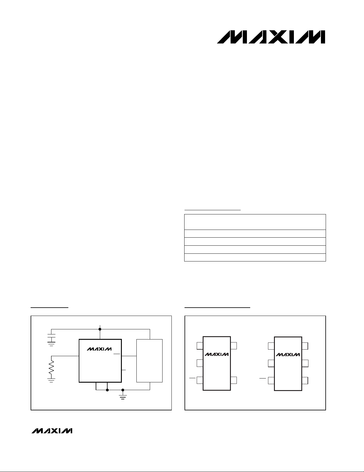
Pin ConfigurationsTypical Operating Circuit
*A minimum order of 2500 pc. is required for SOT packages.
**See Table 1 for selectable output options.
TOP
MARK
ADNT
ADNU
AAHA
AAHB6 SOT23-6-40°C to +125°C
MAX6510HAUT-T**
5 SOT23-5-40°C to +125°CMAX6509HAUK-T
6 SOT23-6-40°C to +125°C
MAX6510CAUT-T**
5 SOT23-5
PIN-
PACKAGE
TEMP. RANGE
-40°C to +125°C
MAX6509CAUK-T
PART*
For pricing, delivery, and ordering information, please contact Maxim/Dallas Direct! at
1-888-629-4642, or visit Maxim’s website at www.maxim-ic.com.
+2.7V TO +5.5V
0.1µF
V
R
SET
( ) ARE FOR MAX6510.
CC
MAX6509
SET
MAX6510
GND
OUT
(OUT)
GND(OUTSET)
HYST
INT
V
µP
GND
CC
TOP VIEW
15SET
MAX6509
2
GND
34
OUT
SOT23-5
V
CC
HYST
SET
16V
MAX6510
2
GND
34
SOT23-6
5
CC
OUTSET
HYSTOUT, OUT
Page 2
µA
MAX6509/MAX6510
Resistor-Programmable
SOT Temperature Switches
2 _______________________________________________________________________________________
ABSOLUTE MAXIMUM RATINGS
ELECTRICAL CHARACTERISTICS
(V
CC
= +2.7V to +5.5V, TA= T
MIN
to T
MAX
, unless otherwise noted. Typical values are at TA= +25°C.) (Note 1)
Stresses beyond those listed under “Absolute Maximum Ratings” may cause permanent damage to the device. These are stress ratings only, and functional
operation of the device at these or any other conditions beyond those indicated in the operational sections of the specifications is not implied. Exposure to
absolute maximum rating conditions for extended periods may affect device reliability.
Note 1: 100% production tested at TA= +25°C. Specifications over temperature limits are guaranteed by design.
Reference to GND Supply Voltage (V
CC
).................-0.3V to +6V
OUT (MAX6509) ....................................................-0.3V to +6V
OUT, OUT (MAX6510).............................-0.3V to (V
CC
+ 0.3V)
SET, HYST, OUTSET ..................................-0.3V to (V
CC
+ 0.3V)
Output Current (all pins) .....................................................20mA
Input Current (all pins) ........................................................20mA
Continuous Power Dissipation (T
A
= +70°C)
5-Pin SOT23 (derate 7.1mW/°C above +70°C).............571mW
6-Pin SOT23 (derate 8.7mW/°C above +70°C).............696mW
Operating Temperature Range .........................-40°C to +125°C
Junction Temperature......................................................+150°C
Storage Temperature Range .............................-65°C to +150°C
Lead Temperature (soldering, 10s) .................................+300°C
5.5
±0.1
V
OUTSET
= V
CC
OUTSET = unconnected
OUT, active high
OUT, open drain
V
OUTSET
= GND
OUT, active low
V
OUT
= V
CC
(MAX6509)
I
OUT
= 5mA
I
OUT
= 5mA, OUTSET = GND or V
CC
±0.5 ±3.7
TA= -40°C to 0°C
0.85 · V
CC
0.72 · V
CC
0.55 ·V
CC
V
OUTSET Current I
OUTSET
-5.5
µAMAX6510
OUTSET Voltage V
OUTSET
0.2 · V
CC
MAX6510
HYST Input Threshold
HYST Input Leakage
1
µA
V
IH
VCC- 0.4
V
Output Voltage High V
OH
VCC- 0.4
V
Open-Drain Output Leakage
Current
Output Voltage Low V
OL
0.3
V
I
OUT
10
µA
OUT Impedance to V
CC
V
IL
0.4
60 100 160
kΩOUTSET = unconnected (MAX6510)
Temperature Threshold
Hysteresis
T
HYST
2
°C
10
HYST = GND
HYST = V
CC
Temperature Threshold
Accuracy
Supply Current I
CC
32 50
µA
∆T
TH
±0.5 ±4.7
°C
MAX6509
TA= 0°C to +125°C
PARAMETER SYMBOL MIN TYP MAX UNITS
Supply Voltage Range V
CC
2.7 5.5
V
CONDITIONS
47 80
OUTSET = GND or VCC(MAX6510)
97 165
OUTSET = unconnected, OUT = low
Page 3
MAX6509/MAX6510
Resistor-Programmable
SOT Temperature Switches
_______________________________________________________________________________________ 3
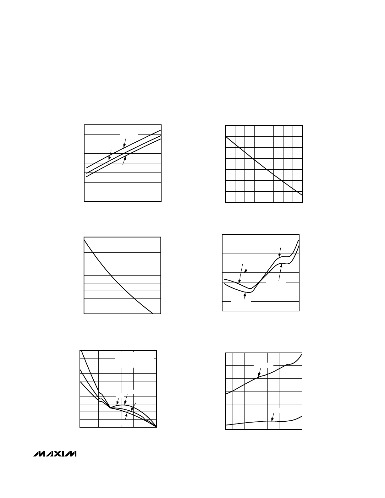
__________________________________________Typical Operating Characteristics
(VCC= +5V, R
PULL-UP
= 10kΩ (MAX6509 only), TA= +25°C, unless otherwise noted.)
SUPPLY CURRENT vs. TEMPERATURE
50
45
40
35
30
25
SUPPLY CURRENT (µA)
20
15
10
VCC = +3.3V
R
= 0
SET
OUTSET = GND (MAX6510)
-50 0-25 25 50 75 100 125
R
SET
(T
100
90
80
70
60
(kΩ)
50
SET
R
40
30
20
10
0
0 20406080100120140
VCC = +5V
VCC = +2.7V
TEMPERATURE (°C)
vs. TEMPERATURE
= 0°C TO +125°C)
A
TEMPERATURE (°C)
MAX6509/10 toc01
MAX6509/10 toc03
R
vs. TEMPERATURE
SET
= -40°C TO 0°C)
(T
160
150
140
130
(kΩ)
SET
R
120
110
100
90
-40 -30 -25-35 -20 -15 -10 -5 0
A
TEMPERATURE (°C)
TRIP THRESHOLD OFFSET
0.20
0.15
0.10
0.05
0
-0.05
SET POINT OFFSET (°C)
-0.10
-0.15
-0.20
-50 0-25 25 50 75 100 125
vs. TEMPERATURE
VCC = +2.7V
VCC = +3.3V
VCC = +5V
VCC = +3.3V
VCC = +2.7V
TEMPERATURE (°C)
MAX6509/10 toc02
MAX6509/10 toc04
TRIP POINT ERROR
vs. SET TEMPERATURE
1.0
0.9
0.8
0.7
0.6
0.5
0.4
ERROR (°C)
0.3
0.2
0.1
0
-40 -25 0 25 50 75 100 125
VCC = +5V
1% R
SET
SET RESISTOR TEMPCO
200ppm
R
SET
50ppm
TEMPERATURE (°C)
MAX6509/10 toc05
100ppm
HYSTERESIS vs. TEMPERATURE
12
HYST = V
10
8
6
HYSTERESIS (°C)
4
2
0
-40 25 50-25 0 75 100 125
TEMPERATURE (°C)
CC
HYST = GND
MAX6509/10 toc06
Page 4

MAX6509/MAX6510
Resistor-Programmable
SOT Temperature Switches
4 _______________________________________________________________________________________
Pin Description
2 2 GroundGND
3 — Open-Drain Output. Reset to high impedance during power-on.
OUT
— 3
Open-Drain with Internal Pull-Up Resistor, Active-High, or Active-Low Output.
See Table 1. Reset to deassert during power-on.
4 4 Hysteresis Selection. Hysteresis is 10°C for HYST = VCC, 2°C for HYST = GND.HYST
OUT,
OUT
5 6
Power-Supply Input
— 5
Trilevel Control Input:
OUTSET = VCCsets OUT to active high.
OUTSET = GND sets OUT to active low.
OUTSET = Unconnected sets OUT to open drain with internal pull-up resistor.
OUTSET
V
CC
11 SET Temperature Set Point. Connect an external 1% resistor from SET to GND to set trip point.
Detailed Description
The MAX6509/MAX6510 fully integrated temperature
switches incorporate two temperature-dependent references and one comparator. One reference exhibits a
positive temperature coefficient, and the other has a
negative temperature coefficient. The temperature at
which the two reference voltages are equal determines
the temperature trip point. Pin-selectable 2°C or 10°C
hysteresis keeps the output from oscillating when the
temperature is close to the threshold. The MAX6509
has an active-low, open-drain output structure that can
only sink current. The MAX6510 has three different output options from which to choose (Table 1).
The MAX6509/MAX6510 are programmable for a wide
range of temperature thresholds from -40°C to +125°C.
The temperature threshold is set by an external resistor
between SET and GND. The MAX6509 output easily
interfaces with a microprocessor (µP) reset input
(Figure 2). The MAX6510 output is intended for applications such as driving a fan control switch (Figure 3).
Hysteresis Input
The HYST pin is a CMOS-compatible input that selects
hysteresis at either a high level (10°C for HYST = V
CC
)
or a low level (2°C for HYST = GND). Hysteresis prevents the output from oscillating when the temperature
is near the trip point. Do not leave HYST unconnected.
Connect HYST to GND or VCC. Other input voltages
cause increased supply current.
Choose the set-hot temperature (H) or set-cold temperature (C) option to ensure that the trip point is accurate
and the hysteresis is in the right direction. A MAX6509
or MAX6510 with the H suffix will first trip at the correct
point when temperature is increasing. For example, a
MAX6509HAUK-T or MAX6510HAUT-T with its trip point
set to 100°C will assert when its temperature rises
above +100°C, and will not deassert until its temperature drops below +100°C minus the selected hysteresis
value (e.g., +98°C if 2°C hysteresis is chosen). Conversely, if the trip temperature of a MAX6509CAUK-T or
MAX6510CAUT-T is -40°C, the output asserts at
-40°C as temperature falls, and deasserts when temperature rises above -40°C plus the hysteresis value
(e.g., -38°C if 2°C hysteresis is chosen) as shown in
Figure 4.
Output Selection
The MAX6509 provides an open-drain output. The
MAX6510 features three output options selectable by
OUTSET (Table 1).
Table 1. OUTSET-Selectable Outputs
PIN
FUNCTION
MAX6509 MAX6510
NAME
OUTSET OUT
Connected to V
CC
Active high
Connected to GND Active low
Unconnected
Open drain with internal
pull-up resistor
Page 5

MAX6509/MAX6510
Resistor-Programmable
SOT Temperature Switches
_______________________________________________________________________________________ 5
Figure 1. Block and Functional Diagrams
NEGATIVE
TEMPCO
REFERENCE
NEGATIVE
TEMPCO
REFERENCE
OUTSET = V
NEGATIVE
TEMPCO
REFERENCE
MAX6509
OUT
V
POSITIVE
TEMPCO
REFERENCE
HYST
NETWORK
OUT
HYST
MAX6509HAUK-T
V
OUT
OUT
POSITIVE
TEMPCO
REFERENCE
CC
POSITIVE
TEMPCO
REFERENCE
HYST
NETWORK
MAX6510HAUT-T
HYST
NETWORK
HYST
OUT
HYST
OUT
V
MAX6509CAUK-T
WITH A PULL-UP RESISTOR
T
TH
HYSTERESIS*
MAX6510
T
TH
HYSTERESIS*
MAX6509
WITH A PULL-UP RESISTOR
T
TH
HYSTERESIS*
TEMP
TEMP
TEMP
NEGATIVE
TEMPCO
REFERENCE
POSITIVE
TEMPCO
REFERENCE
OUTSET = V
CC
MAX6510CAUT-T
HYST
NETWORK
*HYSTERESIS IS 10°C FOR HYST = V
OUT
HYST
OUT
AND 2°C FOR HYST = GND.
CC
T
TH
HYSTERESIS*
MAX6510
TEMP
Page 6

MAX6509/MAX6510
Resistor-Programmable
SOT Temperature Switches
6 _______________________________________________________________________________________
Applications Information
Thermal Considerations
The MAX6509/MAX6510 supply current is typically
32µA. When used to drive high-impedance loads, the
devices dissipate negligible power; therefore, the die
temperature is essentially the same as the package
temperature. The key to accurate temperature monitoring is good thermal contact between the MAX6509/
MAX6510 package and the device being monitored. In
some applications, the SOT23-5 and SOT23-6 packages may be small enough to fit underneath a socketed
µP, allowing the device to monitor the µP’s temperature
directly. Use the monitor’s output to reset the µP, assert
an interrupt, or trigger an external alarm. Accurate temperature monitoring depends on the thermal resistance
between the device being monitored and the
MAX6509/MAX6510 die.
The rise in die temperature due to self-heating is given
by the following formula:
∆TJ= P
DISS
· θ
JA
where P
DISS
is the power dissipated by the
MAX6509/MAX6510, and θ
JA
is the package’s thermal
resistance. The typical thermal resistance is 115°C/W
for the SOT23-6 package. To limit the effects of selfheating, minimize the output currents. For example, if
the MAX6510 sinks 5mA, the output voltage is guaranteed to be less than 0.3V; therefore, an additional
1.5mW of power is dissipated within the IC. This corresponds to a 0.173°C shift in the die temperature in the
SOT23-6.
Temperature-Window Detector
The MAX6509/MAX6510 temperature switch outputs
assert when the die temperature is outside the programmed range. Combining the outputs of a set-cold
and a set-hot device creates an over/undertemperature
detector. The MAX6509/MAX6510 are designed to form
two complementary pairs, each containing one cold trip
point output and one hot trip point output. The assertion
of either output alerts the system to an out-of-range temperature. The MAX6510 push-pull output stages can be
ORed to produce a thermal out-of-range alarm. More
favorably, a MAX6509HAUK-T and MAX6509CAUK-T
can be directly wire-ORed with a single external resistor to accomplish the same task (Figure 5).
The temperature window (alarms or detectors as in
Figure 5) can be used to accurately determine when a
device’s temperature falls out of a programmed range,
for example -3°C to +75°C as shown in Figure 5. The
thermal overrange signal can be used to assert a ther-
Figure 3. Overtemperature Fan Control
Figure 4. Temperature Response
Figure 2. Microprocessor Alarm/Reset
+3.3V
V
CC
µP
INT
SHUTDOWN
OR
RESET
R
PULL-UP
100k
HEAT
OUT
HYST
V
CC
MAX6509
SET
GND
+5V
V
CC
µPFAN
R
SET
TEMPERATURE
-38°C
-40°C
OUT
MAX6509H
OUT
MAX6510C
OUTSET = GND
HEAT
98°C
V
OUTSET SET
CC
MAX6510
HYST
OUTGND
98°C100°C
T THRESHOLD = 65°C100°C
R
SET
THYST = 2°C
THRESHOLD
SET HOT
SET COLD
-38°C-40°C
T
= -10°C
Page 7

mal shutdown, power-up, recalibration, or other temperature-dependent function.
Low-Cost, Fail-Safe Temperature Monitor
In high-performance/high-reliability applications, multiple temperature monitoring is important. The high-level
integration and low cost of the MAX6509/MAX6510
facilitate the use of multiple temperature monitors to
increase system reliability. Figure 6 shows two
MAX6510s with different temperature thresholds. This
ensures that fault conditions that can overheat the monitored device cause no permanent damage. The first
temperature monitor activates the fan when the die
temperature exceeds +45°C. The second MAX6510
triggers a system shutdown if the die temperature
reaches +75°C. The second temperature monitor’s output asserts when a wide variety of destructive fault conditions occur, including latchups, short circuits, and
cooling-system failures.
Set-Point Resistor
To set the trip-point temperature, connect a resistor
between SET and GND. The resistor’s value is determined either from the R
SET
vs. Temperature graphs
(see Typical Operating Characteristics) or from the
equations below.
To set the temperature trip point from -40°C to 0°C, use
the following equation:
R
SET(kΩ)
= [(1.3258 · 105) / (T+1.3)] - 310.1693 -
[(5.7797 · 106) / (T+1.3)2]
To set the temperature trip point from 0°C to +125°C,
use the following equation:
R
SET(kΩ)
= [(8.3793 · 104) / T] - 211.3569 +
[(1.2989 · 105) / T2]
where T is the trip temperature in Kelvin.
MAX6509/MAX6510
Resistor-Programmable
SOT Temperature Switches
_______________________________________________________________________________________ 7
+5V
Figure 5. Temperature-Window Detector
Figure 6. Low-Power, High-Reliability, Fail-Safe Temperature
Monitor
Chip Information
TRANSISTOR COUNT: 234
V
CC
MAX6510HAUT
GND
HYST
OUTSET
V
CC
MAX6509CAUT
HYST
+5V
V
GND
CC
OUT
OUT
OUTSET
SET
R
SET
30k
OVERTEMP
UNDERTEMP
V
CC
R
SET
100k
R
PULL-UP
100k
OUT OF RANGE
OUT OF RANGE
+5V
V
CC
HEAT
GND
P
µ
HEAT
R
55k
V
CC
HYST
SET
SET
OUTSET
MAX6510HAUT
HYST
OUTSET
MAX6510HAUT
GND
OUT
SET
OUT
V
TEMPERATURE
FAULT
R
SET
30k
FAN
CONTROL
V
CC
CC
V
CC
R
SET
30k
GND
OUT OUT
HYST
GND
V
CC
MAX6509CAUKMAX6509HAUK
SET
HYST
R
100k
SET
Page 8

MAX6509/MAX6510
Resistor-Programmable
SOT Temperature Switches
________________________________________________________Package Information
Maxim cannot assume responsibility for use of any circuitry other than circuitry entirely embodied in a Maxim product. No circuit patent licenses are
implied. Maxim reserves the right to change the circuitry and specifications without notice at any time.
8 _____________________Maxim Integrated Products, 120 San Gabriel Drive, Sunnyvale, CA 94086 408-737-7600
© 2003 Maxim Integrated Products Printed USA is a registered trademark of Maxim Integrated Products.
SOT-23 5L .EPS
PACKAGE OUTLINE, SOT-23, 5L
21-0057
PACKAGE OUTLINE, SOT-23, 6L
21-0058
1
E
1
6LSOT.EPS
1
F
1
 Loading...