

Maxim MAX6364PUT44-T, MAX6364PUT46-T, MAX6364PUT26-T, MAX6364PUT29-T, MAX6364LUT44-T Datasheet
...
For free samples and the latest literature, visit www.maxim-ic.com or phone 1-800-998-8800.
For small orders, phone 1-800-835-8769.
General Description
The MAX6361/MAX6363/MAX6364 supervisory circuits
reduce the complexity and number of components
required for power-supply monitoring and battery control
functions in microprocessor (µP) systems. The circuits significantly improve system reliability and accuracy compared to that obtainable with separate ICs or discrete
components. Their functions include µP reset, backupbattery switchover, and power failure warning.
The MAX6361/MAX6363/MAX6364 operate from supply
voltages as low as +1.2V. The factory preset reset
threshold voltage ranges from 2.32V to 4.63V (see
Ordering Information). These devices provide a manual
reset input (MAX6361), battery-on output (MAX6363),
and an auxiliary adjustable reset input (MAX6364). In
addition, each part type is offered in three reset output
versions: an active-low push-pull reset, an active-low
open-drain reset, and an active-high push-pull reset
(see Selector Guide at end of data sheet).
Applications
Features
♦ Low +1.2V Operating Supply Voltage
(V
CC
or V
BATT
)
♦ Precision Monitoring of +5.0V, +3.3V, +3.0V, and
+2.5V Power-Supply Voltages
♦ Debounced Manual Reset Input (MAX6361)
♦ Battery-On Output Indicator (MAX6363)
♦ Auxiliary User-Adjustable RESET IN (MAX6364)
♦ Three Available Output Structures
Push-Pull RESET, Open-Drain RESET,
Push-Pull RESET
♦ RESET/RESET Valid Down to 1.2V Guaranteed
(V
CC
or V
BATT
)
♦ Power-Supply Transient Immunity
♦ 150ms (min) Reset Timeout Period
♦ Small 6-Pin SOT23 Package
MAX6361/MAX6363/MAX6364
SOT23, Low-Power µP Supervisory Circuits
with Battery Backup
________________________________________________________________ Maxim Integrated Products 1
19-1615; Rev 0; 1/00
Ordering Information
Pin Configurations
Note: These parts offer a choice of reset threshold voltages.
From Table 1, select the suffix corresponding to the desired
threshold voltage and insert it into the part number to complete
it. When ordering from the factory, there is a 2500-piece minimum on the SOT package (tape-and-reel only).
GND
V
CC
MR
16BATT
5 OUT
RESET, RESET
MAX6361
TOP VIEW
2
34
SOT23-6
Computers
Controllers
Intelligent Instruments
Critical µP/µC
Power Monitoring
Fax Machines
Industrial Control
POS Equipment
Portable/Battery-Powered
Equipment
Selector Guide appears at end of data sheet.
Typical Operating Circuit appears at end of data sheet.
Pin Configurations continued at end of data sheet.
6 SOT23-6-40°C to +85°CMAX6364HUT_ _-T
6 SOT23-6-40°C to +85°CMAX6364PUT_ _-T
6 SOT23-6-40°C to +85°C
MAX6364LUT_ _-T
6 SOT23-6-40°C to +85°C
6 SOT23-6-40°C to +85°CMAX6363HUT_ _-T
MAX6363PUT_ _-T
6 SOT23-6-40°C to +85°C
6 SOT23-6-40°C to +85°C
MAX6363LUT_ _-T
6 SOT23-6
PIN-PACKAGETEMP. RANGE
-40°C to +85°C
MAX6361HUT_ _-T
6 SOT23-6-40°C to +85°CMAX6361PUT_ _-T
MAX6361LUT_ _-T
PART
MAX6361/MAX6363/MAX6364
SOT23, Low-Power µP Supervisory Circuits
with Battery Backup
2 _______________________________________________________________________________________
ABSOLUTE MAXIMUM RATINGS
ELECTRICAL CHARACTERISTICS
(VCC= +2.4V to +5.5V, V
BATT
= 3V, TA= -40°C to +85°C, reset not asserted, typical values are at TA= +25°C, unless otherwise
noted.) (Note 1)
Stresses beyond those listed under “Absolute Maximum Ratings” may cause permanent damage to the device. These are stress ratings only, and functional
operation of the device at these or any other conditions beyond those indicated in the operational sections of the specifications is not implied. Exposure to
absolute maximum rating conditions for extended periods may affect device reliability.
Terminal Voltages (with respect to GND)
VCC, BATT, OUT...................................................-0.3V to +6V
RESET (open drain)..............................................-0.3V to +6V
BATT ON, MR, RESET IN .....................-0.3V to (V
OUT
+ 0.3V)
RESET, RESET......................................-0.3V to (V
OUT
+ 0.3V)
Input Current
V
CC
Peak ............................................................................1A
V
CC
Continuous ............................................................250mA
BATT Peak ....................................................................250mA
BATT Continuous ............................................................40mA
GND ................................................................................75mA
Output Current
OUT................................Short-Circuit Protection for up to 10s
RESET, RESET, BATT ON ..............................................20mA
Continuous Power Dissipation (T
A
= +70°C)
6-Pin SOT23 (derate 8.70mW/°C above +70°C) .........696mW
Operating Temperature Range
MAX636_ .........................................................-40°C to +85°C
Storage Temperature Range .............................-65°C to +150°C
Lead Temperature (soldering, 10s) .................................+300°C
PARAMETER SYMBOL CONDITIONS MIN TYP MAX UNITS
V
0 5.5
No load (Note 2)
VCC,
V
BATT
Operating Voltage Range,
VCCor V
BATT
Supply Current
(excluding I
OUT
)
I
CC
No load, VCC> V
TH
VCC= 2.8V
VCC= 3.6V
VCC= 5.5V
10 30
11 35
15 50
µA
µA
1
3
TA= +25°C
TA= -40°C to +85°C
V
BATT
= 2.8V,
VCC= 0
I
SUPPLY
I
SUPPLY
in Battery-Backup
Mode (excluding I
OUT
)
BATT Standby Current I
BATT
5.5V > VCC>
(V
BATT
+ 0.2V)
TA= +25°C
TA= -40°C to +85°C
-0.1 0.02
-1.0 0.02
µA
Ω
1.25
2.25
4.6
VCC= 4.75V, I
OUT
≤ 150mA
VCC= 3.15V, I
OUT
≤ 65mA
VCC= 2.38V, I
OUT
≤ 25mA
R
ON
VCCto OUT On-Resistance
V
OUT
in Battery-Backup Mode
Battery-Switchover Threshold
(VCC- V
BATT
)
Reset Threshold
VCCFalling Reset Delay
Reset-Active Timeout Period t
RP
V
TH
V
BATT
= 4.5V, I
OUT
≤ 20mA
V
BATT
= 3.0V, I
OUT
≤ 10mA
V
BATT
= 2.25V, I
OUT
≤ 5mA
V
CC
< V
TH
MAX636_UT46
VCCfalling at 10V/ms
V
BATT
- 0.2
V
BATT
- 0.15
V
BATT
- 0.15
20
-20
4.50 4.63 4.75
4.25 4.38 4.50
3.00 3.08 3.15
2.85 2.93 3.00
2.55 2.63 2.70
2.25 2.32 2.38
35
150 280
ms
µs
V
mV
V
Power-up
Power-down
MAX636_UT23
MAX636_UT26
MAX636_UT29
MAX636_UT31
MAX636_UT44
V
MAX6361/MAX6363/MAX6364
SOT23, Low-Power µP Supervisory Circuits
with Battery Backup
_______________________________________________________________________________________ 3
ELECTRICAL CHARACTERISTICS (continued)
(VCC= +2.4V to +5.5V, V
BATT
= 3V, TA= -40°C to +85°C, reset not asserted, typical values are at TA= +25°C, unless otherwise
noted.) (Note 1)
Note 1: Overtemperature limits are guaranteed by design and not production tested.
Note 2: V
BATT
can be 0 anytime or VCCcan go down to 0 if V
BATT
is active (except at startup).
PARAMETER SYMBOL MIN TYP MAX UNITSCONDITIONS
Output Voltage V
OL
0.4
V
Output Short-Circuit Current
60
mA
I
SINK
= 3.2mA, V
BATT
= 2.1V
Sink current, VCC= 5V
RESET Output Leakage Current
I
LK
1
µA
MR Input Voltage
0.7 · V
CC
V
Pull-Up Resistance
20
kΩ
Minimum Pulse Width
1
µs
Glitch Immunity
100
ns
MR to Reset Delay
120
ns
MAX636_P only
VCC= 3.3V
VCC= 3.3V
RESET Output Voltage
V
OL
0.3
V
Reset asserted,
V
BATT
= 0
Input Threshold
1.185 1.235 1.285
V
RESET IN Leakage Current ±0.01 ±25 nA
1.5 µsOverdrive voltage = 50mV, RESET IN fallingRESET IN to Reset Delay
10 30 100
µASource current, V
BATT
≥ 2V
V
IH
V
IL
0.3 · V
CC
RESET Output Voltage
V
OH
0.7 · V
CC
V
Reset asserted,
V
BATT
= 0
V
OL
0.3
V
OH
0.8 · V
CC
Reset not asserted
Reset not asserted
(MAX636_L only)
I
SOURCE
= 500µA,
V
CC
≥ V
TH(MAX)
I
SINK
= 1.6mA,
VCC≥ V
TH(MAX)
0.8 · V
CC
0.4
I
SOURCE
= 1mA,
VCC≥ 1.8V
I
SOURCE
= 200µA,
VCC≥ 1.2V
I
SINK
= 100µA,
VCC≥ 1.2V
I
SINK
= 1.6mA,
VCC≥ 2.1V
MANUAL RESET (MAX6361 only)
BATT ON (MAX6363 only)
RESET IN (MAX6364 only)

MAX6361/MAX6363/MAX6364
SOT23, Low-Power µP Supervisory Circuits
with Battery Backup
4 _______________________________________________________________________________________
Typical Operating Characteristics
(TA= +25°C, unless otherwise noted.)
12
14
16
18
20
SUPPLY CURRENT vs. TEMPERATURE
(NO LOAD)
MAX6361 toc01
TEMPERATURE (°C)
SUPPLY CURRENT (µA)
-40 20 40-20 0 60 80
V
BATT
= 0
V
CC
= 5.0V
0
0.2
0.6
0.4
0.8
1.0
1.2
BATTERY SUPPLY CURRENT
(BACKUP MODE) vs. TEMPERATURE
MAX6361 toc02
TEMPERATURE (°C)
BATTERY SUPPLY CURRENT (µA)
-40 20 40-20 0 60 80
V
BATT
= 2.0V
VCC = 0
V
BATT
= 2.8V
0
1
4
3
2
5
6
7
BATTERY TO OUT ON-RESISTANCE
vs. TEMPERATURE
MAX6361 toc03
TEMPERATURE (°C)
BATT TO OUT ON-RESISTANCE (Ω)
-40 20 40-20 0 60 80
V
BATT
= 5.0V
I
OUT
= 25mA
V
CC
= 0
V
BATT
= 2.8V
V
BATT
= 2.0V
0
0.3
0.9
0.6
1.2
VCC TO OUT ON-RESISTANCE
vs. TEMPERATURE
MAX6361 toc04
TEMPERATURE (°C)
V
OUT
TO OUT ON-RESISTANCE (Ω)
-40 20 40-20 0 60 80
VCC = 3.0V
I
OUT
= 65mA
VCC = 4.5V
I
OUT
= 150mA
VCC = 2.3V
I
OUT
= 25mA
190
195
205
200
210
RESET TIMEOUT PERIOD
vs. TEMPERATURE
MAX6361 toc05
TEMPERATURE (°C)
RESET TIMEOUT PERIOD (ms)
-40 20 40-20 0 60 80
0
30
15
75
60
45
135
120
105
90
VCC TO RESET PROPAGATION DELAY
vs. TEMPERATURE
MAX6361 toc06
TEMPERATURE (°C)
PROGAGATION DELAY (µs)
-40 20 40-20 0 60 80
VCC FALLING
0.25V/ms
1V/ms
10V/ms
2.0
3.0
2.5
5.0
4.5
4.0
3.5
RESET THRESHOLD
vs. TEMPERATURE
MAX6361 toc07
TEMPERATURE (°C)
THRESHOLD (V)
-40 20 40-20 0 60 80
MAX636_46
MAX636_26
1 10010 1k 10k
MAXIMUM TRANSIENT DURATION
vs. RESET THRESHOLD OVERDRIVE
MAX6361 toc08
RESET THRESHOLD OVERDRIVE V
TH
- VCC (mV)
MAXIMUM TRANSIENT DURATION (µs)
400
300
350
250
200
0
50
150
100
MAX636_46
MAX636_26
RESET OCCURS
ABOVE CURVE
0
3
2
1
4
5
6
7
8
9
10
01234
BATTERY SUPPLY CURRENT
vs. SUPPLY VOLTAGE
MAX6361 toc09
V
CC
(V)
BATTERY SUPPLY CURRENT (µA)
V
BATT
= 2.8V
V
BATT
= 2.5V
V
TH
= 2.93V
V
BATT
= 2.3V
MAX6361/MAX6363/MAX6364
SOT23, Low-Power µP Supervisory Circuits
with Battery Backup
_______________________________________________________________________________________ 5
1.234
1.235
1.236
MAX6364
RESET IN THRESHOLD
vs. TEMPERATURE
MAX6361 toc10
TEMPERATURE (°C)
THRESHOLD (V)
-40 20 40-20 0 60 80
Typical Operating Characteristics (continued)
(TA= +25°C, unless otherwise noted.)
1.0
1.9
1.6
1.3
2.8
2.5
2.2
MAX6364
RESET IN TO RESET PROPAGATION DELAY
vs. TEMPERATURE
MAX6361 toc11
TEMPERATURE (°C)
PROPAGATION DELAY (µs)
-40 20 40-20 0 60 80
V
OD
= 50mV
Pin Description
Detailed Description
The Typical Operating Circuit shows a typical connec-
tion for the MAX6361/MAX6363/MAX6364 family. OUT
powers the static random-access memory (SRAM). OUT
is internally connected to VCCif VCCis greater than the
reset threshold, or to the greater of VCCor V
BATT
when
VCCis less than the reset threshold. OUT can supply up
to 150mA from V
CC
. When VCCis higher than V
BATT
, the
BATT ON (MAX6363) output is low. When VCCis lower
than V
BATT
, an internal MOSFET connects the backup
battery to OUT. The on-resistance of the MOSFET is a
function of backup-battery voltage and is shown in the
Battery to Out On-Resistance vs. Temperature graph in
the Typical Operating Characteristics section.
Backup-Battery Input. When VCCfalls below the reset threshold, BATT switches to OUT if V
BATT
is 20mV
greater than VCC. When VCCrises 20mV above V
BATT
, VCCswitches to OUT. The 40mV hysteresis
prevents repeated switching if V
CC
falls slowly.
BATT6
MAX6363 Battery-On Output. BATT ON goes high in battery backup mode.
BATT ON
MAX6364 Reset Input. When RESET IN falls below 1.235V, reset is asserted. Reset output remains
asserted as long as RESET IN is low and for at least 150ms (t
RP
) after RESET IN goes high.
RESET IN
Supply Voltage. Reset is asserted when VCCdrops below the reset threshold voltage (VTH). Reset
remains asserted until V
CC
rises above VTHand for at least 150ms after VCCrises above VTH.
V
CC
4
Output. OUT sources from VCCwhen it is above the reset threshold (VTH), and from the greater of VCCor
BATT when VCCis below VTH.
OUT5
MAX6361 Manual-Reset Input. Maintaining logic low on MR asserts a reset. Reset output remains assert-
ed for at least 150ms (t
RP
) after MR transitions from low to high. Leave unconnected or connected to V
CC
if not used.
MR
3
GroundGND2
PIN
Active-Low Reset Output (for L and P versions). RESET remains low while VCCis below the reset threshold and for at least 150ms (t
RP
) after VCCrises above the reset threshold. RESET also asserts when MR
or RESET IN is low.
RESET
Active-High Reset Output (for H versions). RESET remains high while VCCis below the reset threshold
and for at least 150ms (t
RP
) after VCCrises above the reset threshold. RESET also asserts when MR or
RESET IN is low.
RESET
1
FUNCTIONNAME

MAX6361/MAX6363/MAX6364
Backup-Battery Switchover
In a brownout or power failure, it may be necessary to
preserve the contents of the RAM. With a backup battery installed at BATT, the MAX6361/MAX6363/
MAX6364 automatically switch the RAM to backup
power when VCCfalls. The MAX6363 has a BATT ON
output that goes high when in battery-backup mode.
These devices require two conditions before switching
to battery-backup mode:
1) VCCmust be below the reset threshold.
2) VCCmust be below V
BATT
. Table 2 lists the status
of the inputs and outputs in battery-backup mode.
The device will not power up if the only voltage
source is on BATT. OUT will only power up from
VCCat startup.
Manual Reset Input (MAX6361 only)
Many µP-based products require manual reset capability, allowing the operator, a test technician, or external
logic circuitry to initiate a reset. For the MAX6361, a logic
low on MR asserts reset. Reset remains asserted while
MR is low, and for a minimum of 150ms (tRP) after it
returns high. MR has an internal 20kΩ pull-up resistor.
This input can be driven with TTL/CMOS logic levels or
with open-drain/collector outputs. Connect a normally
open momentary switch from MR to GND to create a
manual reset function; external debounce circuitry is not
required. If MR is driven from long cables or the device
is used in a noisy environment, connect a 0.1µF capacitor from MR to GND to provide additional noise immunity.
Reset In (MAX6364 only)
RESET IN is compared to an internal 1.235V reference.
If the voltage at RESET IN is less than 1.235V, reset is
asserted. The RESET IN comparator may be used as
an undervoltage detector to signal a failing power supply. It can also be used as a secondary power-supply
reset monitor.
Reset Output
A µP’s reset input starts the µP in a known state. The
MAX6361/MAX6363/MAX6364 µP supervisory circuits
assert a reset to prevent code-execution errors during
power-up, power-down, and brownout conditions.
RESET is guaranteed to be a logic low or high depending on the device chosen (see Ordering Information).
RESET or RESET asserts when VCCis below the reset
threshold and for at least 150ms (tRP) after VCCrises
above the reset threshold. RESET or RESET also
asserts when MR is low (MAX6361) and when RESET
IN is less than 1.235V (MAX6364).
Applications Information
Operation Without a Backup
Power Source
The MAX6361/MAX6363/MAX6364 were designed for
battery-backed applications. If a backup battery is not
used, connect VCCto OUT and connect BATT to GND.
Replacing the Backup Battery
If BATT is decoupled with a 0.1µF capacitor to ground,
the backup power source can be removed while V
CC
remains valid without danger of triggering a reset pulse.
The device does not enter battery-backup mode when
VCCstays above the reset threshold voltage.
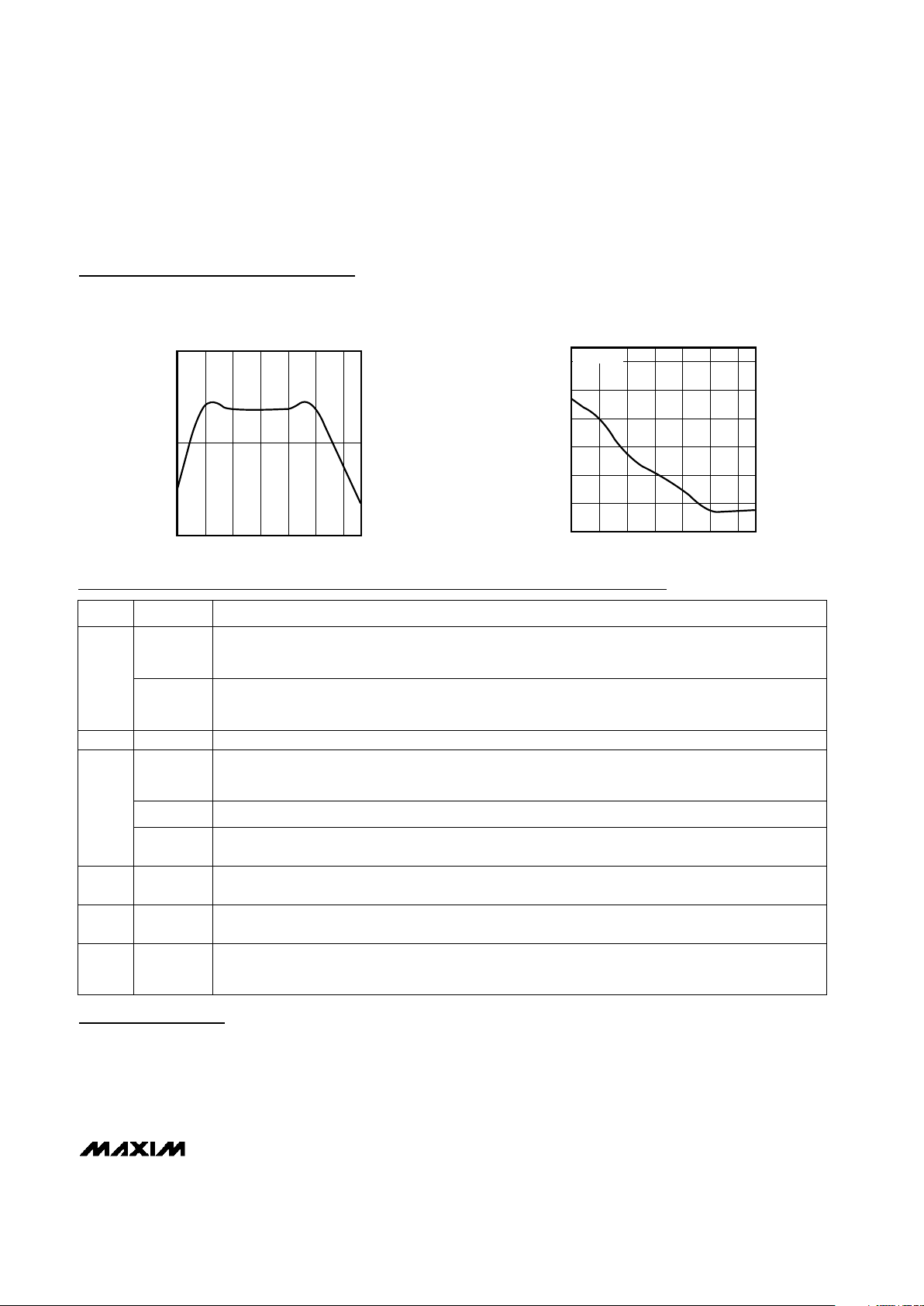
Negative-Going VCCTransients
These supervisors are relatively immune to short-duration, negative-going VCCtransients. Resetting the µP
when VCCexperiences only small glitches is usually not
desirable.
The Typical Operating Characteristics section shows a
graph of Maximum Transient Duration vs. Reset
Threshold Overdrive for which reset is not asserted.
The graph was produced using negative-going V
CC
pulses, starting at VCCand ending below the reset
threshold by the magnitude indicated (reset threshold
overdrive). The graph shows the maximum pulse width
SOT23, Low-Power µP Supervisory Circuits
with Battery Backup
6 _______________________________________________________________________________________
PIN STATUS
V
CC
Disconnected from OUT
OUT Connected to BATT
BATT
Connected to OUT. Current drawn from
the battery is less than 1µA (at V
BATT
=
2.8V, excluding I
OUT
) when VCC= 0.
RESET/RESET
Asserted
BATT ON High state
MR, RESET IN
Inputs ignored
Table 2. Input and Output Status in
Battery-Backup Mode
SUFFIX
46 4.50 4.63
44 4.25 4.38
31 3.00 3.08
4.75
4.50
3.15
23 2.25
29 2.85 2.93
2.32
26 2.55 2.63
2.38
3.00
2.70
RESET THRESHOLD RANGES (V)
Table 1. Reset Threshold Ranges
MIN MAXTYP

MAX6361/MAX6363/MAX6364
SOT23, Low-Power µP Supervisory Circuits
with Battery Backup
_______________________________________________________________________________________ 7
*Sample stock generally held on standard versions only. Contact factory for availability of nonstandard versions.
Device Marking Codes
Selector Guide
that a negative-going VCCtransient can typically have
without triggering a reset pulse. As the amplitude of the
transient increases (i.e., goes further below the reset
threshold), the maximum allowable pulse width
decreases. Typically, a VCCtransient that goes 100mV
below the reset threshold and lasts for 30µs will not
trigger a reset pulse.
A 0.1µF bypass capacitor mounted close to the V
CC
pin provides additional transient immunity.
✓
✓
RESET
PUSH-PULL
✓
✓
✓
RESET
IN
✓
✓
✓
RESET
PUSH-PULL
✓
✓
MAX6364PUT_ _
MAX6364HUT_ _
RESET
OPEN-DRAIN
✓
MAX6363LUT_ _
✓
MAX6363PUT_ _
✓
MAX6363HUT_ _
MAX6364LUT_ _
✓
MAX6361HUT_ _
PART
BATT
ON
MANUAL RESET INPUT,
MR
AAGO
AAGU
AAGT
AAGS
AAGR
AAGV
AAGG
AAGF
AAGW
AAGQ
AAGN
AAGP
AAGH
AAGL
AAGI
TOP MARK
AAGJ
AAGM
AAGK
MAX6364PUT29*
MAX6364HUT29
MAX6364HUT31
MAX6364HUT44
MAX6364HUT46*
MAX6364HUT26
MAX6364LUT44
MAX6364LUT46*
MAX6364HUT23
MAX6364PUT23
MAX6364PUT31
MAX6364PUT26
MAX6364LUT31
MAX6364PUT46*
MAX6364LUT29*
PART
MAX6364LUT26
MAX6364PUT44
MAX6364LUT23
AAFW
AAGC
AAGB
AAGA
AAFZ
AAGD
AAFO
AAFN
AAGE
AAFY
AAFV
AAFX
AAFP
AAFT
AAFQ
TOP MARK
AAFR
AAFU
AAFS
MAX6363PUT29*
MAX6363HUT29
MAX6363HUT31
MAX6363HUT44
MAX6363HUT46*
MAX6363HUT26
MAX6363LUT44
MAX6363LUT46*
MAX6363HUT23
MAX6363PUT23
MAX6363PUT31
MAX6363PUT26
MAX6363LUT31
MAX6363PUT46*
MAX6363LUT29*
PART
MAX6363LUT26
MAX6363PUT44
MAX6363LUT23
AAEM
AAES
AAER
AAEQ
AAEP
AAET
AAEE
AAED
AAEU
AAEO
AAEL
AAEN
AAEF
AAEJ
AAEG
TOP MARK
AAEH
AAEK
AAEI
MAX6361HUT29
MAX6361HUT31
MAX6361HUT44
MAX6361HUT46*
MAX6361HUT26
MAX6361HUT23
MAX6361PUT31
MAX6361PUT46*
MAX6361PUT44
MAX6361PUT29*
MAX6361LUT44
MAX6361LUT46*
MAX6361PUT23
MAX6361PUT26
MAX6361LUT31
MAX6361LUT29*
PART
MAX6361LUT26
MAX6361LUT23
✓✓
MAX6361PUT_ _
✓✓
MAX6361LUT_ _

MAX6361/MAX6363/MAX6364
SOT23, Low-Power µP Supervisory Circuits
with Battery Backup
Maxim cannot assume responsibility for use of any circuitry other than circuitry entirely embodied in a Maxim product. No circuit patent licenses are
implied. Maxim reserves the right to change the circuitry and specifications without notice at any time.
8 _____________________Maxim Integrated Products, 120 San Gabriel Drive, Sunnyvale, CA 94086 408-737-7600
© 2000 Maxim Integrated Products Printed USA is a registered trademark of Maxim Integrated Products.
Package Information
GND
V
CC
BATT ON
16BATT
5 OUT
RESET, RESET
MAX6363
TOP VIEW
2
34
GND
V
CC
RESET IN
16BATT
5 OUT
RESET, RESET
MAX6364
2
34
SOT23-6
SOT23-6
Pin Configurations (continued) Typical Operating Circuit
BUS
RESET
OUT
GND
BATT
RESET IN
V
CC
V
CC
V
CC
GND
µP
GND
SRAM
0.1µF
R2
R1
0.1µF
RESET
UNREGULATED
DC VOLTAGE
3.6V Li+
BATTERY
2.4V TO 5.5V
MAX6364
Chip Information
TRANSISTOR COUNT: 720
 Loading...