

General Description
The MAX6037 family of low-dropout, micropower voltage references offer fixed and adjustable output voltage options ranging from 1.184V to 5V. Connect an
external resistive-divider on the MAX6037_ADJ to
adjust the output voltage from 1.184V to 5V. The other
devices in the MAX6037 family feature fixed output voltages of 1.25V, 2.048V, 2.5V, 3.0V, 3.3V, and 4.096V.
The MAX6037 offers shutdown functionality with an
active-low shutdown (500nA, max).
These series-mode voltage references operate from a
2.5V to 5.5V supply and consume 275µA (max) quiescent current. The output is stable driving loads from
0.02µF to 1µF and can source and sink 5mA of load
current. The MAX6037 offers a low temperature coefficient of 25ppm/°C and initial accuracy of ±0.2% (max).
The low dropout voltage (100mV, max at 1mA) and
supply-independent, low supply current make the
MAX6037 ideal for battery-powered applications.
The MAX6037 is available in the miniature 5-pin SOT23
package and is specified over the -40°C to +125°C
automotive temperature range.
Applications
Medical Equipment Portable Equipment
Wireless LAN Precision Regulators
Features
♦ Adjustable V
OUT
: 1.184V to 5V
♦ Fixed Outputs: 1.25V, 2.048V, 2.5V, 3.0V, 3.3V,
and 4.096V
♦ Shutdown Current < 500nA (max)
♦ 25ppm/°C (max) Temperature Coefficient (A Grade)
♦ ±0.2% (max) Initial Accuracy (A Grade)
♦ Low 100mV (max) Dropout Voltage at 1mA Load
Current
♦ 2.5V to 5.5V Input Voltage Range
♦ 5mA Sink and Source Current Capability
♦ Available in 5-Pin SOT23 Package
♦ Operates Over the Automotive Temperature
Range: -40°C to +125°C
MAX6037
Low-Power, Fixed and Adjustable Reference
with Shutdown in SOT23
________________________________________________________________ Maxim Integrated Products 1
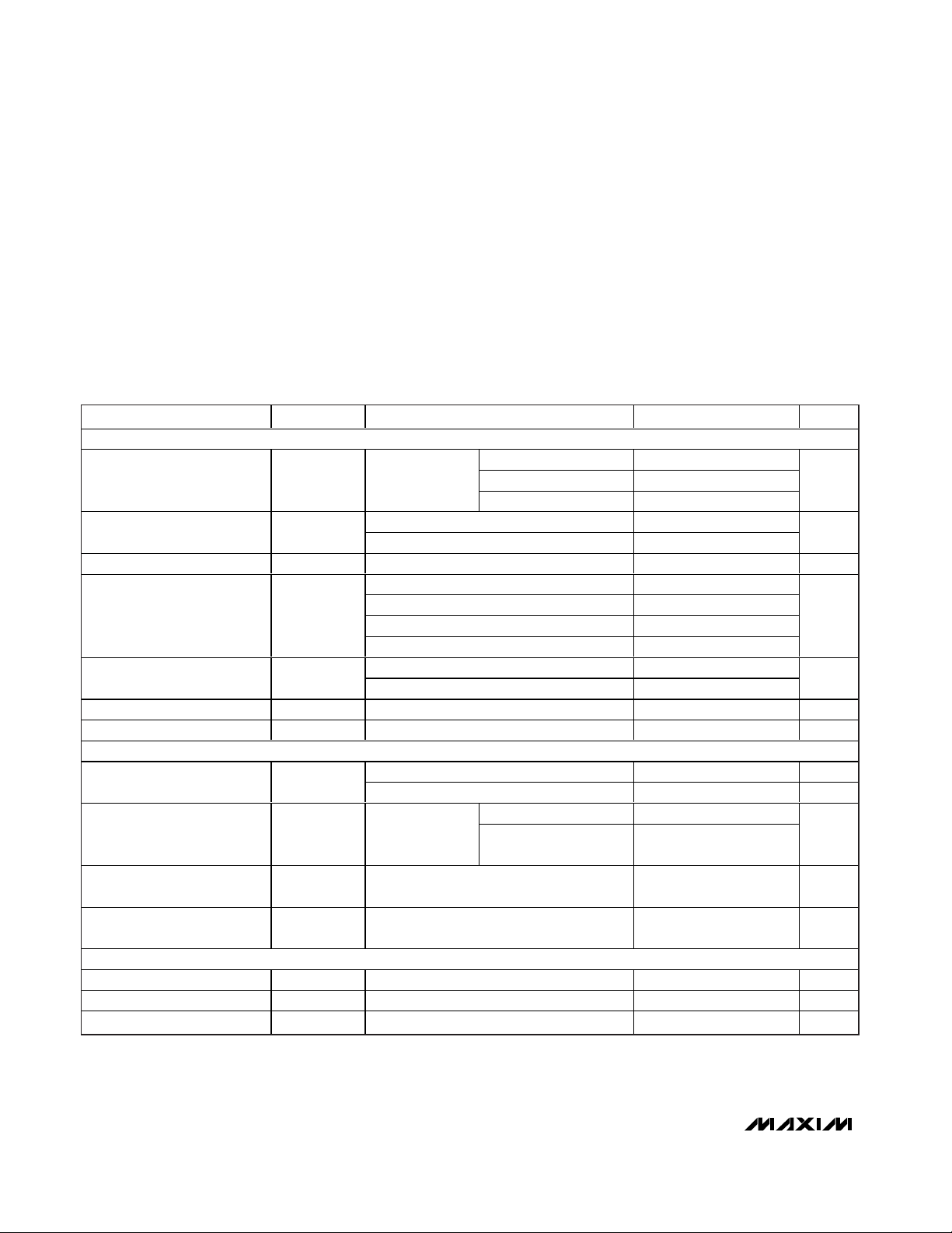
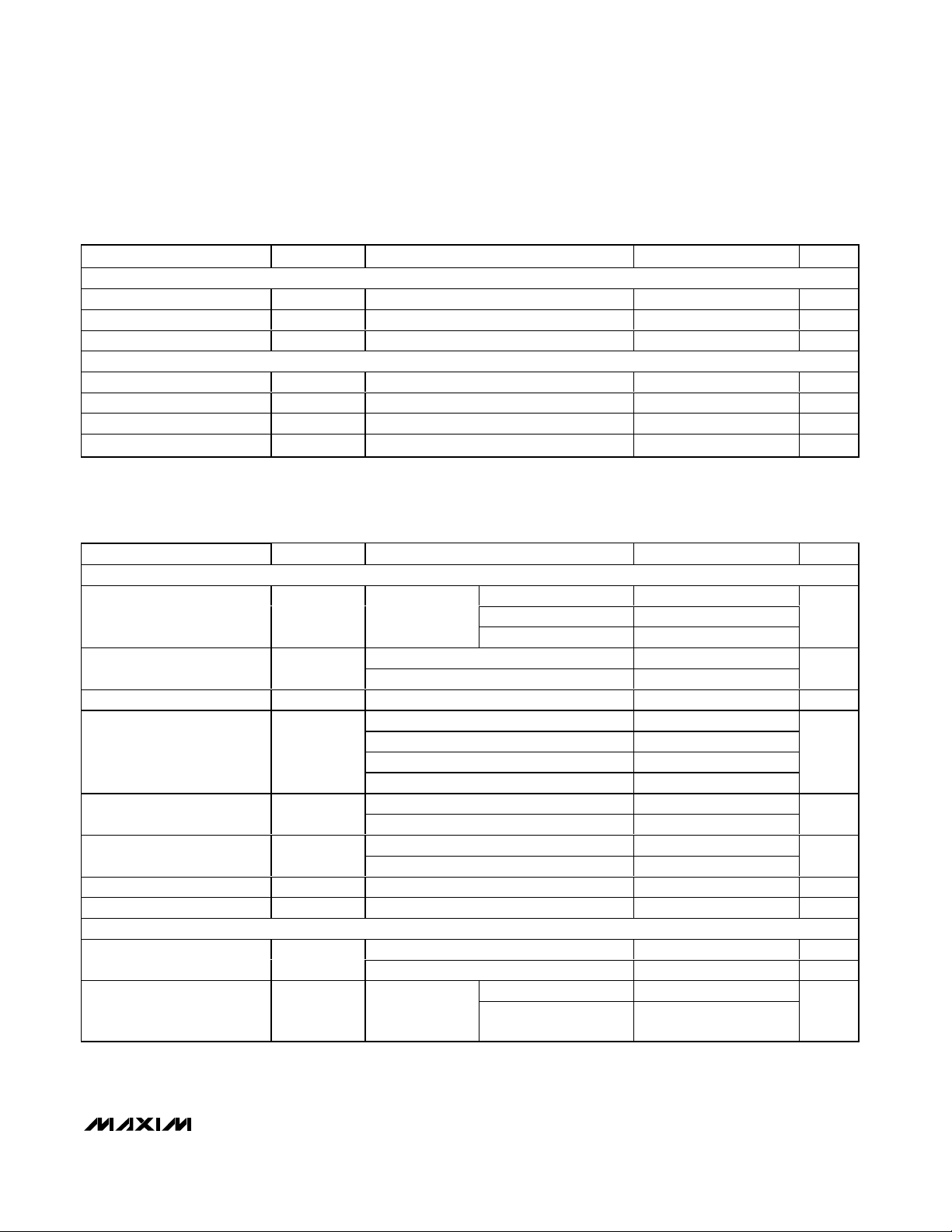
Ordering Information/Selector Guide
19-3192; Rev 1; 12/07
For pricing delivery, and ordering information please contact Maxim Direct at 1-888-629-4642,
or visit Maxim’s website at www.maxim-ic.com.
Ordering Information/Selector Guide continued at end of data sheet.
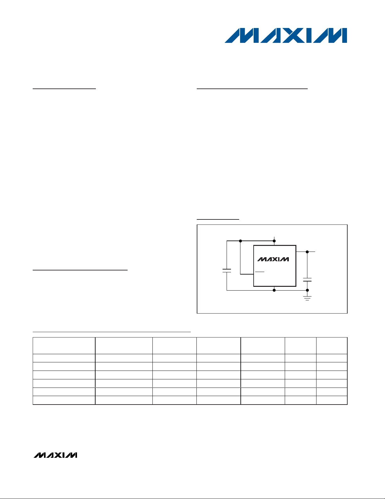
Typical Operating Circuit
OUT
*OPTIONAL
*
IN
2.5V TO 5.5V INPUT
GND
SHDN
REFERENCE
OUTPUT
0.02µF
TO 1µF
MAX6037
Pin Configuration appears at end of data sheet.
PART
OUTPUT
VOLTAGE (V)
INITIAL
MAX TEMPCO
(ppm/°C)
PIN-PACKAGE
PKG
CODE
TOP
MARK
MAX6037AAUK12+T 1.25 0.2 25 5 SOT23-5 U5-2 AEIV
MAX6037BAUK12+T 1.25 0.3 50 5 SOT23-5 U5-2 AEIW
MAX6037CAUK12+T 1.25 0.5 50 5 SOT23-5 U5-2 AEIX
MAX6037AAUK21+T 2.048 0.2 25 5 SOT23-5 U5-2 AEIY
MAX6037BAUK21+T 2.048 0.3 50 5 SOT23-5 U5-2 AEIZ
MAX6037CAUK21+T 2.048 0.5 50 5 SOT23-5 U5-2 AEJA
+Denotes a lead-free package.
T = Tape and reel.
Note: All devices are specified over the -40°C to +125°C operating temperature range.
ACCURACY %
MAX6037
Low-Power, Fixed and Adjustable Reference
with Shutdown in SOT23
2 _______________________________________________________________________________________
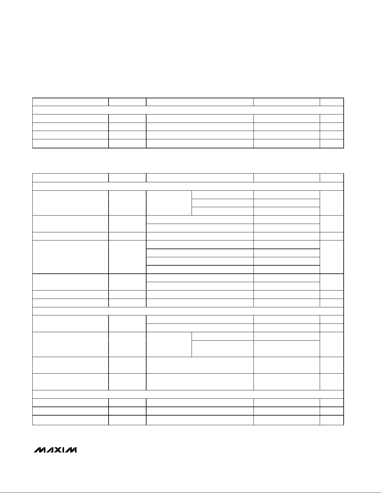
ABSOLUTE MAXIMUM RATINGS
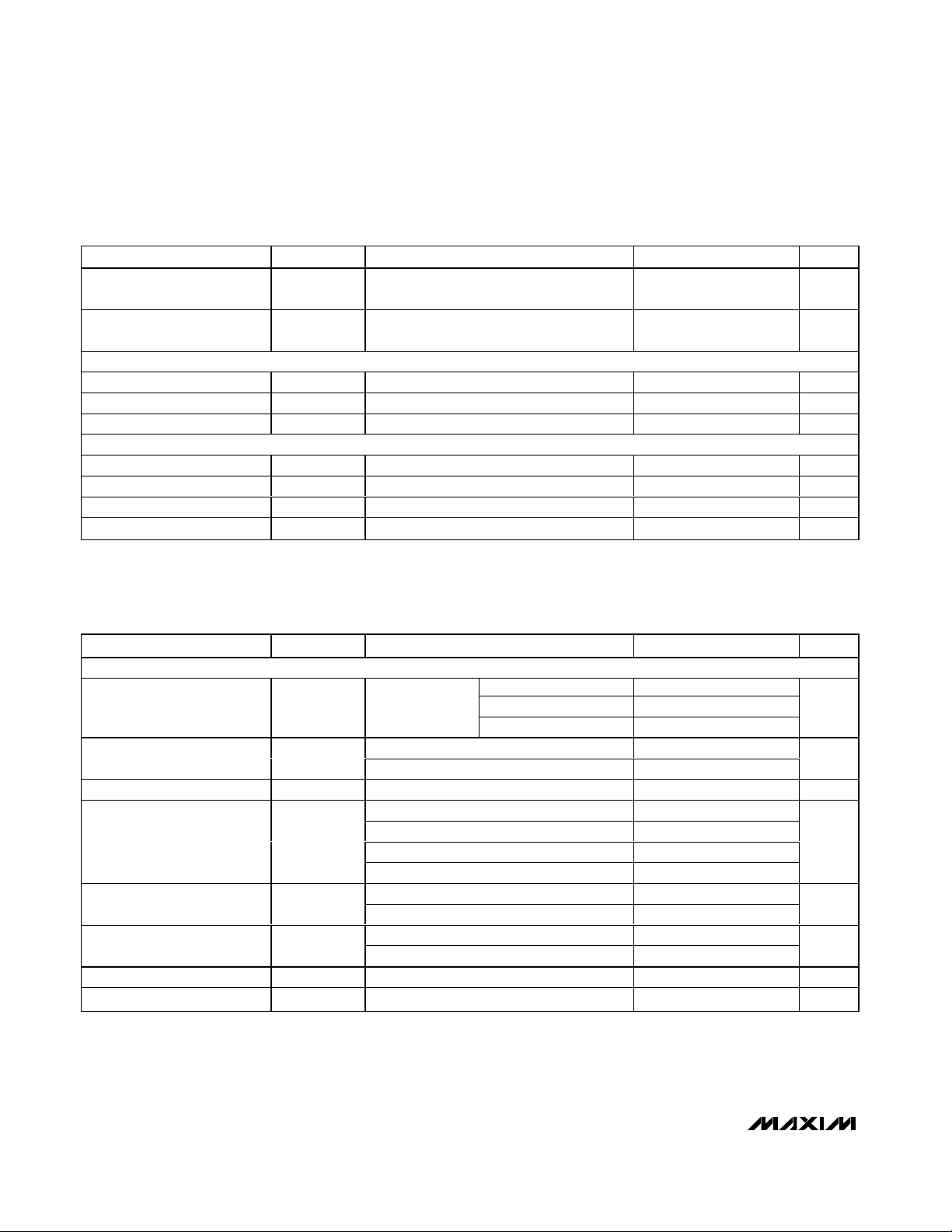
ELECTRICAL CHARACTERISTICS—MAX6037_12 (V
OUT
= 1.25V)
(V
IN
= V
SHDN
= +3V, I
OUT
= 0, C
OUT
= 0.1µF, TA= T
MIN
to T
MAX
, unless otherwise noted. Typical values are at TA= +25°C.) (Note 1)
Stresses beyond those listed under “Absolute Maximum Ratings” may cause permanent damage to the device. These are stress ratings only, and functional
operation of the device at these or any other conditions beyond those indicated in the operational sections of the specifications is not implied. Exposure to
absolute maximum rating conditions for extended periods may affect device reliability.
IN, OUT, SHDN, ADJ to GND...................................-0.3V to +6V
Output Short Circuit to GND or IN............................. Continuous
Continuous Power Dissipation (T
A
= +70°C)
5-Pin SOT23 (derate 7.1mW/°C above +70°C)............571mW
Operating Temperature Range .........................-40°C to +125°C
Junction Temperature......................................................+150°C
Storage Temperature Range .............................-65°C to +150°C
Lead Temperature (soldering, 10s) .................................+300°C
PARAMETER SYMBOL CONDITIONS
OUTPUT
MAX6037A_12 (0.2%)
MAX6037B_12 (0.3%)
Output Voltage V
OUT
TA = +25°C
MAX6037C_12 (0.5%)
V
MAX6037A_12 6 25
Output-Voltage Temperature
Coefficient (Note 2, 4)
TCV
OUT
MAX6037B/C_12 6 50
Line Regulation
2.5V ≤ VIN ≤ 5.5V
%/V
Sourcing: 0 ≤ I
OUT
≤ 1mA
Sourcing: 1mA ≤ I
OUT
≤ 5mA
Sinking: -1mA ≤ I
OUT
≤ 0
Load Regulation
Sinking: -5mA ≤ I
OUT
≤ -1mA
Short to GND 16
OUT Short-Circuit Current I
SC
Short to IN 32
mA
Thermal Hysteresis (Note 3)
Long-Term Stability
1000h at TA = +25°C
DYNAMIC
f = 0.1Hz to 10Hz 6
Noise Voltage e
OUT
f = 10Hz to 1kHz 15
Initial power-up
Turn-On Settling Time t
R
To V
OUT
= 0.1%
of final value,
C
OUT
= 0.02µF
V
IN
= 3V, SHDN pulled
from low to high
75
µs
Output Impedance when
Disabled
Z
OUT
VIN = 3V, V
SHDN
= 0V
kΩ
Capacitive-Load Stability
Range (Note 4)
C
OUT
1µF
INPUT
Supply Voltage Range V
IN
Guaranteed by line regulation test 2.5 5.5 V
Quiescent Supply Current I
IN
275 µA
Shutdown Supply Current I
SHDN
V
SHDN
= 0V
500 nA
∆V
/∆V
OUT
IN
∆V
/∆I
OUT
OUT
∆V
/cycle 485 ppm
OUT
∆V
/time
OUT
MIN TYP MAX UNITS
1.2475 1.250 1.2525
1.2462 1.250 1.2538
1.2438 1.250 1.2563
0.02
0.0006 0.0096
0.008 0.072
0.006 0.072
0.025 0.12
0.014 0.12
133 ppm
360
125
190
0.05
ppm/°C
%/mA
µV
P-P
µV
RMS
MAX6037
Low-Power, Fixed and Adjustable Reference
with Shutdown in SOT23
_______________________________________________________________________________________ 3
ELECTRICAL CHARACTERISTICS—MAX6037_12 (V
OUT
= 1.25V) (continued)
(V
IN
= V
SHDN
= +3V, I
OUT
= 0, C
OUT
= 0.1µF, TA= T
MIN
to T
MAX
, unless otherwise noted. Typical values are at TA= +25°C.) (Note 1)
PARAMETER SYMBOL CONDITIONS
MIN
TYP
MAX
UNITS
SHUTDOWN (SHDN)
Logic-High Input Voltage V
ENH
2.5V ≤ VIN ≤ 5.5V 2.0 V
Logic-Low Input Voltage V
ENL
2.5V ≤ VIN ≤ 5.5V 0.7 V
Logic-High Input Current I
ENH
2.5V ≤ VIN ≤ 5.5V, V
SHDN
= V
IN
nA
Logic-Low Input Current I
ENL
2.5V ≤ VIN ≤ 5.5V, V
SHDN
= 0V
nA
ELECTRICAL CHARACTERISTICS—MAX6037_21 (V
OUT
= 2.048V)
(V
IN
= V
SHDN
= +3V, I
OUT
= 0, C
OUT
= 0.1µF, TA = T
MIN
to T
MAX
, unless otherwise noted. Typical values are at TA = +25°C.) (Note 1)
PARAMETER SYMBOL CONDITIONS
OUTPUT
MAX6037A_21 (0.2%)
MAX6037B_21 (0.3%)
Output Voltage V
OUT
TA = +25°C
MAX6037C_21 (0.5%)
V
MAX6037A_21 6 25
Output-Voltage Temperature
Coefficient (Note 2, 4)
TCV
OUT
MAX6037B/C_21 6 50
Line Regulation
2.5V ≤ VIN ≤ 5.5V
%/V
Sourcing: 0 ≤ I
OUT
≤ 1mA
Sourcing: 1mA ≤ I
OUT
≤ 5mA
Sinking: -1mA ≤ I
OUT
≤ 0
Load Regulation
Sinking: -5mA ≤ I
OUT
≤ -1mA
Short to GND 16
OUT Short-Circuit Current I
SC
Short to IN 32
mA
Thermal Hysteresis (Note 3)
Long-Term Stability
1000h at TA = +25°C
DYNAMIC
f = 0.1Hz to 10Hz 11
Noise Voltage e
OUT
f = 10Hz to 1kHz 25
Initial power-up
Turn-On Settling Time t
R
To V
OUT
= 0.1%
of final value,
C
OUT
= 0.02µF
V
IN
= 3V, SHDN pulled
from low to high
2
ms
Output Impedance when
Disabled
Z
OUT
VIN = 3V, V
SHDN
= 0V
kΩ
Capacitive-Load Stability
Range (Note 4)
C
OUT
1µF
INPUT
Supply Voltage Range V
IN
Guaranteed by line regulation test 2.5 5.5 V
Quiescent Supply Current I
IN
275 µA
Shutdown Supply Current I
SHDN
V
SHDN
= 0V
500 nA
-1000 0.15 +1000
-1000 0.05 +1000
MIN TYP MAX UNITS
2.0439 2.0480 2.0521
2.0418 2.0480 2.0542
2.0378 2.0480 2.0582
∆V
/∆V
OUT
IN
∆V
/∆I
OUT
OUT
∆V
/cycle 458 ppm
OUT
∆V
/time
OUT
0.02
0.0008 0.0107
0.006 0.044
0.004 0.044
0.02 0.195
0.01 0.195
133 ppm
2.1
205
190
0.05
ppm/°C
%/mA
µV
P-P
µV
RMS
MAX6037
Low-Power, Fixed and Adjustable Reference
with Shutdown in SOT23
4 _______________________________________________________________________________________
ELECTRICAL CHARACTERISTICS—MAX6037_21 (V
OUT
= 2.048V) (continued)
(V
IN
= V
SHDN
= +3V, I
OUT
= 0, C
OUT
= 0.1µF, TA = T
MIN
to T
MAX
, unless otherwise noted. Typical values are at TA = +25°C.) (Note 1)
PARAMETER SYMBOL CONDITIONS
SHUTDOWN (SHDN)
Logic-High Input Voltage V
ENH
2.5V ≤ VIN ≤ 5.5V 2.0 V
Logic-Low Input Voltage V
ENL
2.5V ≤ VIN ≤ 5.5V 0.7 V
Logic-High Input Current I
ENH
2.5V ≤ VIN ≤ 5.5V, V
SHDN
= V
IN
nA
Logic-Low Input Current I
ENL
2.5V ≤ VIN ≤ 5.5V, V
SHDN
= 0V
nA
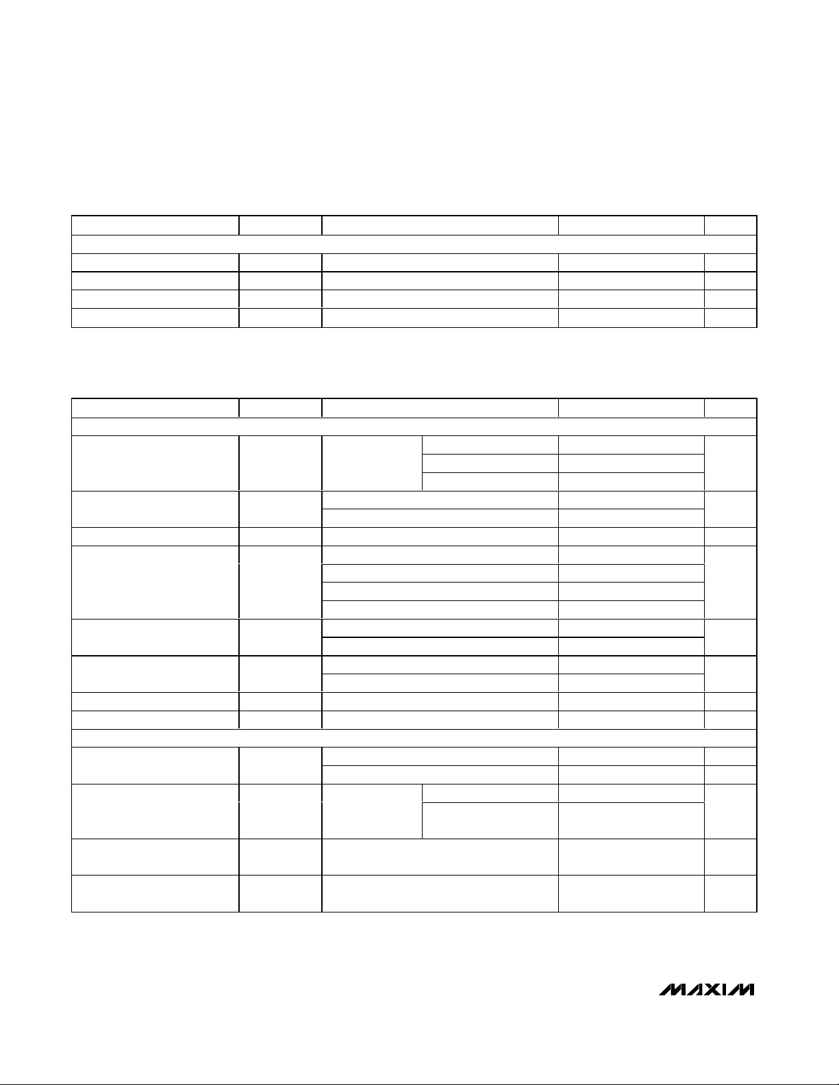
ELECTRICAL CHARACTERISTICS—MAX6037_25 (V
OUT
= 2.500V)
(V
IN
= V
SHDN
= +5V, I
OUT
= 0, C
OUT
= 0.1µF, TA = T
MIN
to T
MAX
, unless otherwise noted. Typical values are at TA = +25°C.) (Note 1)
PARAMETER SYMBOL CONDITIONS
MIN
TYP
MAX
UNITS
OUTPUT
MAX6037A_25 (0.2%)
MAX6037B_25 (0.3%)
Output Voltage V
OUT
TA = +25°C
MAX6037C_25 (0.5%)
V
MAX6037A_25 6 25
Output-Voltage Temperature
Coefficient (Note 2, 4)
TCV
OUT
MAX6037B/C_25 6 50
Line Regulation
(V
OUT
+ 0.2V) ≤ VIN ≤ 5.5V
%/V
Sourcing: 0 ≤ I
OUT
≤ 1mA
Sourcing: 1mA ≤ I
OUT
≤ 5mA
Sinking: -1mA ≤ I
OUT
≤ 0
0.2
Load Regulation
Sinking: -5mA ≤ I
OUT
≤ -1mA
0.2
Short to GND 33
OUT Short-Circuit Current I
SC
Short to IN 32
mA
I
SOURCE
= 1mA 40 100
Dropout Voltage (Note 5)
I
SOURCE
= 5mA
410
mV
Thermal Hysteresis (Note 3)
Long-Term Stability
1000h at TA = +25°C
DYNAMIC
f = 0.1Hz to 10Hz 14
Noise Voltage e
OUT
f = 10Hz to 1kHz 30
Initial power-up 2.2
Turn-On Settling Time t
R
To V
OUT
= 0.1%
of final value,
C
OUT
= 0.02µF
V
IN
= 5V, SHDN pulled
from low to high
2
ms
Output Impedance when
Disabled
Z
OUT
VIN = 5V, V
SHDN
= 0V
kΩ
Capacitive-Load Stability
Range (Note 4)
C
OUT
1µF
MIN TYP MAX UNITS
-1000 0.15 +1000
-1000 0.05 +1000
2.4950 2.500 2.5050
2.4925 2.500 2.5075
2.4875 2.500 2.5125
∆V
OUT
/∆V
IN
0.0004 0.012
0.005 0.036
∆V
/∆I
OUT
OUT
0.003 0.036
0.02
0.01
VIN - V
OUT
∆V
/cycle 514 ppm
OUT
∆V
/time
OUT
0.02
190
133 ppm
250
ppm/°C
%/mA
µV
P-P
µV
RMS
MAX6037
Low-Power, Fixed and Adjustable Reference
with Shutdown in SOT23
_______________________________________________________________________________________ 5
ELECTRICAL CHARACTERISTICS—MAX6037_30 (V
OUT
= 3.000V)
(V
IN
= V
SHDN
= +5V, I
OUT
= 0, C
OUT
= 0.1µF, TA = T
MIN
to T
MAX
, unless otherwise noted. Typical values are at TA = +25°C.) (Note 1)
PARAMETER SYMBOL CONDITIONS
OUTPUT
MAX6037A_30 (0.2%)
MAX6037B_30 (0.3%)
Output Voltage V
OUT
TA = +25°C
MAX6037C_30 (0.5%)
V
MAX6037A_30 6 25
Output-Voltage Temperature
Coefficient (Note 2, 4)
TCV
OUT
MAX6037B/C_30 6 50
Line Regulation
(V
OUT
+ 0.2V) ≤ VIN ≤ 5.5V
%/V
Sourcing: 0 ≤ I
OUT
≤ 1mA
Sourcing: 1mA ≤ I
OUT
≤ 5mA
Sinking: -1mA ≤ I
OUT
≤ 0
0.2
Load Regulation
Sinking: -5mA ≤ I
OUT
≤ -1mA
0.2
Short to GND 33
OUT Short-Circuit Current I
SC
Short to IN 32
mA
I
SOURCE
= 1mA 40 100
Dropout Voltage (Note 5)
I
SOURCE
= 5mA
410
mV
Thermal Hysteresis (Note 3)
Long-Term Stability
1000h at TA = +25°C
DYNAMIC
f = 0.1Hz to 10Hz 17
Noise Voltage e
OUT
f = 10Hz to 1kHz 40
Initial power-up 2.4
Turn-On Settling Time t
R
To V
OUT
= 0.1%
of final value,
C
OUT
= 0.02µF
V
IN
= 5V, SHDN pulled
from low to high
2.1
ms
ELECTRICAL CHARACTERISTICS—MAX6037_25 (V
OUT
= 2.500V) (continued)
(V
IN
= V
SHDN
= +5V, I
OUT
= 0, C
OUT
= 0.1µF, TA = T
MIN
to T
MAX
, unless otherwise noted. Typical values are at TA = +25°C.) (Note 1)
PARAMETER SYMBOL CONDITIONS
INPUT
Supply Voltage Range V
IN
Guaranteed by line regulation test 2.7 5.5 V
Quiescent Supply Current I
IN
275 µA
Shutdown Supply Current I
SHDN
V
SHDN
= 0V
500 nA
SHUTDOWN (SHDN)
Logic-High Input Voltage V
ENH
2.7V ≤ VIN ≤ 5.5V 2.0 V
Logic-Low Input Voltage V
ENL
2.7V ≤ VIN ≤ 5.5V
V
Logic-High Input Current I
ENH
2.7V ≤ VIN ≤ 5.5V, V
SHDN
= V
IN
nA
Logic-Low Input Current I
ENL
2.7V ≤ VIN ≤ 5.5V, V
SHDN
= 0V
nA
MIN TYP MAX UNITS
-1000 0.15 +1000
-1000 0.05 +1000
MIN TYP MAX UNITS
2.9940 3.000 3.0060
2.9910 3.000 3.0090
2.9850 3.000 3.0150
210
0.05
0.75
∆V
OUT
/∆V
IN
0.0004 0.0133
0.005 0.035
∆V
/∆I
OUT
OUT
0.008 0.03
0.02
0.01
VIN - V
OUT
∆V
/cycle 501 ppm
OUT
∆V
/time
OUT
190
133 ppm
ppm/°C
%/mA
µV
P-P
µV
RMS
MAX6037
Low-Power, Fixed and Adjustable Reference
with Shutdown in SOT23
6 _______________________________________________________________________________________
ELECTRICAL CHARACTERISTICS—MAX6037_30 (V
OUT
= 3.000V) (continued)
(V
IN
= V
SHDN
= +5V, I
OUT
= 0, C
OUT
= 0.1µF, TA = T
MIN
to T
MAX
, unless otherwise noted. Typical values are at TA = +25°C.) (Note 1)
PARAMETER SYMBOL CONDITIONS
Output Impedance when
Disabled
Z
OUT
VIN = 5V, V
SHDN
= 0V
kΩ
Capacitive-Load Stability
Range (Note 4)
C
OUT
1µF
INPUT
Supply Voltage Range V
IN
Guaranteed by line regulation test 3.2 5.5 V
Quiescent Supply Current I
IN
275 µA
Shutdown Supply Current I
SHDN
V
SHDN
= 0V
500 nA
SHUTDOWN (SHDN)
Logic-High Input Voltage V
ENH
3.2V ≤ VIN ≤ 5.5V 2.0 V
Logic-Low Input Voltage V
ENL
3.2V ≤ VIN ≤ 5.5V 0.8 V
Logic-High Input Current I
ENH
3.2V ≤ VIN ≤ 5.5V, V
SHDN
= V
IN
nA
Logic-Low Input Current I
ENL
3.2V ≤ VIN ≤ 5.5V, V
SHDN
= 0V
nA
ELECTRICAL CHARACTERISTICS—MAX6037_33 (V
OUT
= 3.300V)
(V
IN
= V
SHDN
= +5V, I
OUT
= 0, C
OUT
= 0.1µF, TA = T
MIN
to T
MAX
, unless otherwise noted. Typical values are at TA = +25°C.) (Note 1)
PARAMETER SYMBOL CONDITIONS
OUTPUT
MAX6037A_33 (0.2%)
MAX6037B_33 (0.3%)
Output Voltage V
OUT
TA = +25°C
MAX6037C_33 (0.5%)
V
MAX6037A_33 6 25
Output-Voltage Temperature
Coefficient (Note 2, 4)
TCV
OUT
MAX6037B/C_33 6 50
Line Regulation
(V
OUT
+ 0.2V) ≤ V
IN
≤ 5.5V
%/V
Sourcing: 0 ≤ I
OUT
≤ 1mA
Sourcing: 1mA ≤ I
OUT
≤ 5mA
Sinking: -1mA ≤ I
OUT
≤ 0
Load Regulation
Sinking: -5mA ≤ I
OUT
≤ -1mA
Short to GND 33
OUT Short-Circuit Current I
SC
Short to IN 32
mA
I
SOURCE
= 1mA 40 100
Dropout Voltage (Note 5)
I
SOURCE
= 5mA
410
mV
Thermal Hysteresis (Note 3)
Long-Term Stability
1000h at TA = +25°C
MIN TYP MAX UNITS
0.02
-1000 0.15 +1000
-1000 0.05 +1000
MIN TYP MAX UNITS
300
210
0.05
3.2934 3.300 3.3066
3.2901 3.300 3.3099
3.2855 3.300 3.3165
∆V
/∆V
OUT
IN
∆V
/∆I
OUT
OUT
VIN - V
OUT
∆V
/cycle 514 ppm
OUT
∆V
OUT
/time
0.0003 0.0133
0.005 0.027
0.002 0.027
0.02 0.212
0.01 0.212
190
133 ppm
ppm/°C
%/mA

MAX6037
Low-Power, Fixed and Adjustable Reference
with Shutdown in SOT23
_______________________________________________________________________________________ 7
ELECTRICAL CHARACTERISTICS—MAX6037_41 (V
OUT
= 4.096V)
(V
IN
= V
SHDN
= +5V, I
OUT
= 0, C
OUT
= 0.1µF, TA = T
MIN
to T
MAX
, unless otherwise noted. Typical values are at TA = +25°C.) (Note 1)
PARAMETER SYMBOL CONDITIONS
UNITS
OUTPUT
MAX6037A_41 (0.2%)
MAX6037B_41 (0.3%)
Output Voltage V
OUT
TA = +25°C
MAX6037C_41 (0.5%)
V
MAX6037A_41 6 25
Output-Voltage Temperature
Coefficient (Note 2, 4)
TCV
OUT
MAX6037B/C_41 6 50
ppm/°C
Line Regulation
(V
OUT
+ 0.2V) ≤ V
IN
≤ 5.5V
%/V
Sourcing: 0 ≤ I
OUT
≤ 1mA
Sourcing: 1mA ≤ I
OUT
≤ 5mA
Sinking: -1mA ≤ I
OUT
≤ 0
Load Regulation
Sinking: -5mA ≤ I
OUT
≤ -1mA
%/mA
ELECTRICAL CHARACTERISTICS—MAX6037_33 (V
OUT
= 3.300V) (continued)
(V
IN
= V
SHDN
= +5V, I
OUT
= 0, C
OUT
= 0.1µF, TA = T
MIN
to T
MAX
, unless otherwise noted. Typical values are at TA = +25°C.) (Note 1)
PARAMETER SYMBOL CONDITIONS
DYNAMIC
f = 0.1Hz to 10Hz 19
Noise Voltage e
OUT
f = 10Hz to 1kHz 45
Initial power-up 2.6
Turn-On Settling Time t
R
To V
OUT
= 0.1%
of final value,
C
OUT
= 0.02µF
V
IN
= 5V, SHDN pulled
from low to high
2.4
ms
Output Impedance when
Disabled
Z
OUT
VIN = 5V, V
SHDN
= 0V
kΩ
Capacitive-Load Stability
Range (Note 4)
C
OUT
1µF
INPUT
Supply Voltage Range V
IN
Guaranteed by line regulation test 3.5 5.5 V
Quiescent Supply Current I
IN
275 µA
Shutdown Supply Current I
SHDN
V
SHDN
= 0V
500 nA
SHUTDOWN (SHDN)
Logic-High Input Voltage V
ENH
3.5V ≤ VIN ≤ 5.5V 2.0 V
Logic-Low Input Voltage V
ENL
3.5V ≤ VIN ≤ 5.5V 0.8 V
Logic-High Input Current I
ENH
3.5V ≤ VIN ≤ 5.5V, V
SHDN
= V
IN
nA
Logic-Low Input Current I
ENL
3.5V ≤ VIN ≤ 5.5V, V
SHDN
= 0V
nA
MIN TYP MAX UNITS
0.02
-1000 0.15 +1000
-1000 0.05 +1000
330
210
0.05
µV
µV
P-P
RMS
∆V
/∆V
OUT
OUT
/∆I
IN
OUT
∆V
MIN TYP MAX
4.0878 4.096 4.1042
4.0837 4.096 4.1083
4.0755 4.096 4.1165
0.0003 0.0105
0.004 0.35
0.002 0.027
0.02 0.212
0.01 0.212

MAX6037
Low-Power, Fixed and Adjustable Reference
with Shutdown in SOT23
8 _______________________________________________________________________________________
ELECTRICAL CHARACTERISTICS—MAX6037_41 (V
OUT
= 4.096V) (continued)
(V
IN
= V
SHDN
= +5V, I
OUT
= 0, C
OUT
= 0.1µF, TA = T
MIN
to T
MAX
, unless otherwise noted. Typical values are at TA = +25°C.) (Note 1)
PARAMETER SYMBOL CONDITIONS
MIN
TYP
MAX
UNITS
Short to GND 33
OUT Short-Circuit Current I
SC
Short to IN 32
mA
I
SOURCE
= 1mA 40 100
Dropout Voltage (Note 5)
I
SOURCE
= 5mA
410
mV
Thermal Hysteresis (Note 3)
ppm
Long-Term Stability
1000h at TA = +25°C
ppm
DYNAMIC
f = 0.1Hz to 10Hz 24
µV
P-P
Noise Voltage e
OUT
f = 10Hz to 1kHz 50
µV
RMS
Initial power-up 3.2
Turn-On Settling Time t
R
To V
OUT
= 0.1%
of final value,
C
OUT
= 0.02µF
V
IN
= 5V, SHDN pulled
from low to high
3.2
ms
Output Impedance when
Disabled
Z
OUT
VIN = 5V, V
SHDN
= 0
kΩ
Capacitive-Load Stability
Range (Note 4)
C
OUT
1µF
INPUT
Supply Voltage Range V
IN
Guaranteed by line regulation test 4.3 5.5 V
Quiescent Supply Current I
IN
275 µA
Shutdown Supply Current I
SHDN
V
SHDN
= 0V
500 nA
SHUTDOWN (SHDN)
Logic-High Input Voltage V
ENH
4.3V ≤ VIN ≤ 5.5V 2.0 V
Logic-Low Input Voltage V
ENL
4.3V ≤ VIN ≤ 5.5V 0.8 V
Logic-High Input Current I
ENH
4.3V ≤ VIN ≤ 5.5V, V
SHDN
= V
IN
nA
Logic-Low Input Current I
ENL
4.3V ≤ VIN ≤ 5.5V, V
SHDN
= 0V
nA
VIN - V
∆V
OUT
∆V
OUT
OUT
/cycle 524
/time
0.02
190
133
410
210
0.05
-1000 0.15 +1000
-1000 0.05 +1000

MAX6037
Low-Power, Fixed and Adjustable Reference
with Shutdown in SOT23
_______________________________________________________________________________________ 9
ELECTRICAL CHARACTERISTICS—MAX6037_ADJ (V
OUT
= 1.184V to 5V)
(V
IN
= V
SHDN
= +5V, I
OUT
= 0, TA = T
MIN
to T
MAX
, ADJ shorted to OUT unless otherwise noted. Typical values are at TA = +25°C.)
(Note 1)
PARAMETER SYMBOL CONDITIONS
OUTPUT
MAX6037A_ADJ (0.2%)
MAX6037B_ADJ (0.3%)
Initial Output Voltage (Note 6)
V
OUT
TA = +25°C
MAX6037C_ADJ (0.5%)
V
Output Voltage Range V
OUT
V
MAX6037A_ADJ 6 25
Output-Voltage Temperature
Coefficient (Notes 2, 4, 7)
TCV
OUT
MAX6037B/C_ADJ 6 50
Line Regulation (Note 8)
2.5V ≤ VIN ≤ 5.5V
%/V
Sourcing: 0 ≤ I
OUT
≤ 1mA
Sourcing: 1mA ≤ I
OUT
≤ 5mA
0.1
Sinking: -1mA ≤ I
OUT
≤ 0
Load Regulation
Sinking: -5mA ≤ I
OUT
≤ -1mA
Short to GND 33
OUT Short-Circuit Current I
SC
Short to IN 32
mA
I
SOURCE
= 1mA, V
OUT
= 5V 40 100
Dropout Voltage (Notes 5, 9)
I
SOURCE
= 5mA, V
OUT
= 5V
410
mV
Thermal Hysteresis (Note 3)
Long-Term Stability
1000h at TA = +25°C
DYNAMIC
f = 0.1Hz to 10Hz 6
Noise Voltage (Note 10) e
OUT
f = 10Hz to 1kHz 15
Initial power-up
Turn-On Settling Time t
R
To V
OUT
= 0.1%
of final value,
C
OUT
= 0.02µF
V
IN
= 5V, SHDN pulled
from low to high
75
µs
Output Impedance when
Disabled (Note 11)
Z
OUT
VIN = 5V, V
SHDN
= 0V
MΩ
Capacitive-Load Stability
Range (Note 4)
C
OUT
1µF
INPUT
Supply Voltage Range V
IN
Guaranteed by line regulation test 2.5 5.5 V
Quiescent Supply Current I
IN
250 µA
Shutdown Supply Current I
SHDN
V
SHDN
= 0V
500 nA
ADJ Input Bias Current
(Note 4)
I
ADJ
-50 0.5 +50 nA
MIN TYP MAX UNITS
1.1816 1.1840 1.1864
1.1805 1.1840 1.1875
1.1781 1.1840 1.1899
1.184 VIN - 0.15
∆V
OUT
/∆V
IN
0.0008 0.013
0.012 0.078
∆V
OUT
/∆I
OUT
0.014
0.005 0.12
0.005 0.12
VIN - V
OUT
∆V
/cycle 421 ppm
OUT
∆V
/time
OUT
0.02
190
133 ppm
360
>10
200
0.15
ppm/°C
%/mA
µV
P-P
µV
RMS

MAX6037_25 OUTPUT VOLTAGE
vs. TEMPERATURE (V
OUT
= 2.500V)
MAX6037 toc01
TEMPERATURE (°C)
OUTPUT VOLTAGE (V)
10075-25 0 25 50
2.4925
2.4950
2.4975
2.5000
2.5025
2.5050
2.5075
2.5100
2.4900
-50 125
MAX6037_12 SUPPLY CURRENT
vs. INPUT VOLTAGE (V
OUT
= 1.25V)
MAX6037 toc02
INPUT VOLTAGE (V)
SUPPLY CURRENT (µA)
5.04.54.03.53.0
180
190
200
210
220
230
170
2.5 5.5
TA = +125°C
TA = +25°C
TA = -40°C
MAX6037_12 SUPPLY CURRENT
vs. TEMPERATURE (V
OUT
= 1.25V)
MAX6037 toc03
TEMPERATURE (°C)
SUPPLY CURRENT (µA)
1007550250-25
175
200
225
250
150
-50 125
VIN = +2.5V
VIN = +5.5V
Typical Operating Characteristics
(VIN= +3V for the MAX6037_12 and MAX6037_21; VIN= +5V for the MAX6037_25, MAX6037_30, MAX6037_33, and MAX6037_41;
I
OUT
= 0, C
OUT
= 0.1µF, CIN= 0.1µF, TA= +25°C, unless otherwise specified.)
MAX6037
Low-Power, Fixed and Adjustable Reference
with Shutdown in SOT23
10 ______________________________________________________________________________________
Note 1: All devices are 100% tested at TA= +25°C and are guaranteed by design for TA= T
MIN
to T
MAX
, as specified.
Note 2: Temperature coefficient is measured by the “box” method, i.e., the maximum ∆V
OUT
/ V
OUT
is divided by the maximum ∆T.
Note 3: Thermal hysteresis is defined as the change in +25°C output voltage before and after cycling the device from T
MAX
to
T
MIN
.
Note 4: Not production tested. Guaranteed by design.
Note 5: Dropout voltage is defined as the minimum differential voltage (V
IN
- V
OUT
) at which V
OUT
decreases by 1% from its origi-
nal value at V
IN
= +5.0V.
Note 6: V
OUT
initial accuracy for the MAX6037_ADJ is tested with ADJ shorted to OUT. Actual accuracy will be affected by matching and the temperature coefficient of the external resistors used. Use 1% resistors with low temperature coefficient for
best overall accuracy.
Note 7: The temperature coefficient for the MAX6037_ADJ is specified for the case where ADJ is connected to OUT. For the case
where an external resistive network is used to set the output voltage, actual change in reference output over temperature
will be affected by the temperature coefficient and matching of the external resistors used.
Note 8: The minimum V
IN
is the greater of +2.5V and (V
OUT
+ 0.2V).
Note 9: V
OUT
set to +5V with an external resistive-divider.
Note 10: Noise for the MAX6037_ADJ is specified for a +1.25V output. Noise is proportional to V
OUT
and is greater for higher output
voltages. In addition, external resistors used to set the output voltage can contribute to noise.
PARAMETER SYMBOL CONDITIONS
UNITS
SHUTDOWN (SHDN)
Logic-High Input Voltage V
ENH
2.5V ≤ VIN ≤ 5.5V 2.0 V
Logic-Low Input Voltage V
ENL
2.5V ≤ VIN ≤ 5.5V 0.7 V
Logic-High Input Current I
ENH
2.5V ≤ VIN ≤ 5.5V, V
SHDN
= V
IN
nA
Logic-Low Input Current I
ENL
2.5V ≤ VIN ≤ 5.5V, V
SHDN
= 0V
nA
ELECTRICAL CHARACTERISTICS—MAX6037_ADJ (V
OUT
= 1.184V to 5V) (continued)
(V
IN
= V
SHDN
= +5V, I
OUT
= 0, TA = T
MIN
to T
MAX
, ADJ shorted to OUT unless otherwise noted. Typical values are at TA = +25°C.)
(Note 1)
MIN TYP MAX
-1000 0.15 +1000
-1000 0.05 +1000

MAX6037
Low-Power, Fixed and Adjustable Reference
with Shutdown in SOT23
______________________________________________________________________________________ 11
MAX6037_25 DROPOUT VOLTAGE
vs. SOURCE CURRENT (V
OUT
= 2.500V)
MAC6037 toc04
SOURCE CURRENT (mA)
DROPOUT VOLTAGE (mV)
8642
100
200
300
400
500
600
0
010
TA = +125°C
TA = +25°C
TA = -40°C
MAX6037_12
LOAD REGULATION (V
OUT
= 1.25V)
MAX6037 toc05
OUTPUT CURRENT (mA)
OUTPUT VOLTAGE CHANGE (mV)
50-5
-1
0
1
2
3
4
-2
-10 10
TA = +125°C
TA = +125°C
TA = +25°C
TA = -40°C
TA = -40°C
SINKING CURRENT
SOURCING CURRENT
MAX6037_41
LOAD REGULATION (V
OUT
= 4.096V)
MAX6037 toc06
OUTPUT VOLTAGE CHANGE (mV)
-2
-1
0
1
2
3
4
5
6
-3
OUTPUT CURRENT (mA)
50-5-10 10
TA = +125°C
TA = +125°C
TA = +25°C
TA = -40°C
TA = -40°C
SINKING CURRENT
SOURCING CURRENT
MAX6037_12 LINE REGULATION
vs. TEMPERATURE (V
OUT
= 1.25V)
MAX6037 toc07
INPUT VOLTAGE (V)
OUTPUT VOLTAGE CHANGE (µV)
5.04.54.03.53.0
-60
-40
-20
0
-80
2.5 5.5
TA = +125°C
TA = +25°C
TA = -40°C
MAX6037_25
POWER-SUPPLY REJECTION RATIO
vs. FREQUENCY (V
OUT
= 2.500V)
MAX6037 tpc08
FREQUENCY (kHz)
PSRR (dB)
1001010.10.01
-100
-80
-60
-40
-20
0
-120
0.001 1000
MAX6037_41 SHUTDOWN CURRENT
vs. TEMPERATURE (V
OUT
= 4.096V)
MAX6037 toc09
TEMPERATURE (C)
SHUTDOWN CURRENT (nA)
1007550250-25
0
0.5
1.0
1.5
2.0
2.5
3.0
-0.5
-50 125
MAX6037_12 LINE TRANSIENT
(V
OUT
= 1.25V)
MAX6037 toc10
400µs/div
V
OUT
AC-COUPLED
10mV/div
+3V
V
IN
+3.3V
C
OUT
= 0.1µF
C
IN
= 0
MAX6037_41 LINE TRANSIENT
(V
OUT
= 4.096V)
MAX6037 toc11
400µs/div
V
OUT
AC-COUPLED
10mV/div
5V
V
IN
5.5V
C
OUT
= 0.1µF
C
IN
= 0
MAX6037_12 LOAD TRANSIENT
(V
OUT
= 1.25V)
MAX6037 toc12
1ms/div
V
OUT
AC-COUPLED
2mV/div
-10µA
I
OUT
+10µA
C
OUT
= 1µF
Typical Operating Characteristics (continued)
(VIN= +3V for the MAX6037_12 and MAX6037_21; VIN= +5V for the MAX6037_25, MAX6037_30, MAX6037_33, and MAX6037_41;
I
OUT
= 0, C
OUT
= 0.1µF, CIN= 0.1µF, TA= +25°C, unless otherwise specified.)

MAX6037
Low-Power, Fixed and Adjustable Reference
with Shutdown in SOT23
12 ______________________________________________________________________________________
MAX6037_12 LOAD TRANSIENT
(V
OUT
= 1.25V)
MAX6037 toc13
400µs/div
V
OUT
AC-COUPLED
2mV/div
-10µA
I
OUT
+10µA
C
OUT
= 0.02µF
MAX6037_12 LOAD TRANSIENT
(V
OUT
= 1.25V)
MAX6037 toc14
1ms/div
V
OUT
AC-COUPLED
200mV/div
-5mA
I
OUT
+5mA
C
OUT
= 1µF
MAX6037_12 LOAD TRANSIENT
(V
OUT
= 1.25V)
MAX6037 toc15
1ms/div
V
OUT
AC-COUPLED
200mV/div
-5mA
I
OUT
+5mA
C
OUT
= 0.02µF
MAX6037_41 LOAD TRANSIENT
(V
OUT
= 4.096V)
MAX6037 toc16
1ms/div
V
OUT
AC-COUPLED
2mV/div
-10µA
I
OUT
+10µA
C
OUT
= 1µF
MAX6037_41 LOAD TRANSIENT
(V
OUT
= 4.096V)
MAX6037 toc17
1ms/div
V
OUT
AC-COUPLED
5mV/div
-10µA
I
OUT
+10µA
C
OUT
= 0.02µF
MAX6037_41 LOAD TRANSIENT
(V
OUT
= 4.096V)
MAX6037 toc18
1ms/div
V
OUT
AC-COUPLED
200mV/div
-5mA
I
OUT
+5mA
C
OUT
= 1µF
MAX6037_41 LOAD TRANSIENT
(V
OUT
= 4.096V)
MAX6037 toc19
1ms/div
V
OUT
AC-COUPLED
200mV/div
-5mA
I
OUT
+5mA
C
OUT
= 0.02µF
MAX6037_12 TURN-ON TRANSIENT
(V
OUT
= 1.25V)
MAX6037 toc20
40µs/div
V
OUT
500mV/div
GND
GND
V
IN
+3V
+1.25V
C
OUT
= 0.02µF
MAX6037_41 TURN-ON TRANSIENT
(V
OUT
= 4.096V)
MAX6037 toc21
400µs/div
V
OUT
2V/div
GND
GND
V
IN
+5V
4.096V
C
OUT
= 0.02µF
Typical Operating Characteristics (continued)
(VIN= +3V for the MAX6037_12 and MAX6037_21; VIN= +5V for the MAX6037_25, MAX6037_30, MAX6037_33, and MAX6037_41;
I
OUT
= 0, C
OUT
= 0.1µF, CIN= 0.1µF, TA= +25°C, unless otherwise specified.)

MAX6037
Low-Power, Fixed and Adjustable
Reference with Shutdown in SOT23
______________________________________________________________________________________ 13
MAX6037_12 SHUTDOWN TRANSIENT
(V
OUT
= 1.25V)
MAX6037 toc22
2ms/div
V
OUT
500mV/div
GND
GND
V
SHDN
+3V
1.25V
C
OUT
= 0.02µF
MAX6037_12
EXITING SHUTDOWN TRANSIENT
(V
OUT
= 1.25V)
MAX6037 toc23
10µs/div
V
OUT
500mV/div
GND
GND
V
SHDN
+3V
1.25V
C
OUT
= 0.02µF
MAX6037_41 SHUTDOWN TRANSIENT
(V
OUT
= 4.096V)
MAX6037 toc24
10ms/div
V
OUT
2V/div
GND
GND
V
SHDN
+5V
+4.096V
C
OUT
= 0.02µF
MAX6037_41
EXITING SHUTDOWN TRANSIENT
(V
OUT
= 4.096V)
MAX6037 toc25
400µs/div
V
OUT
2V/div
GND
GND
V
SHDN
+5V
+4.096V
C
OUT
= 0.02µF
Typical Operating Characteristics (continued)
(VIN= +3V for the MAX6037_12 and MAX6037_21; VIN= +5V for the MAX6037_25, MAX6037_30, MAX6037_33, and MAX6037_41;
I
OUT
= 0, C
OUT
= 0.1µF, CIN= 0.1µF, TA= +25°C, unless otherwise specified.)
MAX6037_25 LONG-TERM STABILITY
vs. TIME (V
OUT
= 2.500V)
MAX6037 toc26
TIME (HOURS)
V
OUT
(V)
800600200 400
2.4985
2.4990
2.4995
2.5000
2.5005
2.5010
2.5015
2.5020
2.4980
0 1000
TWO TYPICAL PARTS

MAX6037
Low-Power, Fixed and Adjustable Reference
with Shutdown in SOT23
14 ______________________________________________________________________________________
Pin Description
PIN
FUNCTION
I.C.
Internally connected. (All fixed output
voltage options.) Do not connect anything
to this pin.
1
ADJ
Output Voltage Adjustment Connection.
Connect a resistor-divider between OUT,
ADJ and GND to set the output voltage.
(MAX6037_ADJ only).
2 GND Ground
3
Active-Low Shutdown Input. Pull SHDN
low to disable the device. Connect SHDN
to IN for normal operation.
4IN
Supply Voltage Input. Bypass with a 0.1µF
to 1µF capacitor to GND.
5 OUT
Reference-Voltage Output. Connect an
output capacitor to GND in the 0.02µF to
1µF range.
Typical Operating Characteristics (continued)
(VIN= +3V for the MAX6037_12 and MAX6037_21; VIN= +5V for the MAX6037_25, MAX6037_30, MAX6037_33, and MAX6037_41;
I
OUT
= 0, C
OUT
= 0.1µF, CIN= 0.1µF, TA= +25°C, unless otherwise specified.)
Note 12: Many of the MAX6037 family Typical Operating Characteristics are extremely similar. The extremes of these characteristics
are found in the MAX6037_12 (1.25V output) and the MAX6037_41 (4.096V output). The Typical Operating Characteristics of
the remainder of the MAX6037 family typically lie between those two extremes and can be estimated based on their output
voltages.
MAX6037_41 OUTPUT NOISE
(0.1Hz TO 10Hz)
MAX6037 toc27
1s/div
V
OUT
10µV/div
V
OUT
= 4.096V
MAX6037_12 OUTPUT NOISE
(0.1Hz TO 10Hz)
MAX6037 toc28
1s/div
V
OUT
2µV/div
V
OUT
= 1.25V
GND
INSHDN
( ) MAX6037_AUKADJ.
1 5 OUTI.C. (ADJ)
MAX6037
SOT23
+
TOP VIEW
2
34
Pin Configuration
NAME
SHDN

Detailed Description
The MAX6037 is a family of low-dropout, micropower
voltage references. These devices all feature a shutdown mode by forcing SHDN low, dropping the quiescent current to less than 500nA. The MAX6037 can sink
and source up to 5mA with less than 410mV of dropout
voltage, making them attractive for use in low-voltage
applications. The MAX6037 is available in six fixed output voltages of 1.25V, 2.048V, 2.5V, 3.0V, 3.3V and
4.096V, and an adjustable output version for voltages
between the range of 1.184V and 5V.
Shutdown
The MAX6037 features an active-low shutdown mode.
Pulling SHDN low disables the output and forces the
quiescent current to less than 500nA (typically 50pA).
Connect SHDN to IN for normal operation.
MAX6037_ADJ Adjustable Output Voltage
Set the output voltage on the MAX6037_ADJ by placing
a resistor-divider network between OUT, ADJ, and GND
(See Figure 1). Use the following formula to calculate
the output voltage:
where V
ADJ
= 1.184V. Set R2 = 1MΩ or less. Currents
through Resistor R1 and R2 add to the quiescent supply
current.
Supply Current
The quiescent supply current of the series-mode
MAX6037 family is typically 190µA to 210µA. When the
supply voltage is below the minimum-specified input
voltage during turn-on, the device can draw up to
250µA beyond the nominal supply current. The input
voltage source must be capable of providing this current to ensure reliable turn-on.
Thermal Hysteresis
Output voltage hysteresis is the change of output voltage at TA= +25°C before and after the device is
cycled over its entire operating temperature range. The
typical thermal hysteresis value is 500ppm.
V
R
R
V
OUT ADJ
=+
⎛
⎝
⎜
⎞
⎠
⎟
1
1
2
MAX6037
Low-Power, Fixed and Adjustable Reference
with Shutdown in SOT23
______________________________________________________________________________________ 15
OUT
R2
ADJ
* OPTIONAL
*
IN
2.5V TO 5.5V INPUT
GND
SHDN
R1
REFERENCE
OUTPUT
0.02µF
TO 1µF
MAX6037_ADJ
Figure 1. MAX6037_ADJ Typical Operating Circuit
TEMPERATURE
COEFFICIENT
(ppm/°C)
110
100
16-BIT
14-BIT
12-BIT
10-BIT
8-BIT
0.01
0.1
10
100
1000
1
10,000
18-BIT
20-BIT
OPERATING TEMPERATURE RANGE (T
MAX
- T
MIN
) (°C)
Figure 2. Temperature Coefficient vs. Operating Temperature Range for a 1 LSB Maximum Error

MAX6037
Low-Power, Fixed and Adjustable Reference
with Shutdown in SOT23
16 ______________________________________________________________________________________
Chip Information
TRANSISTOR COUNT: 372
PROCESS: BiCMOS
Turn-On Time
These devices typically turn on and settle to within
0.1% of their final value in 360µs to 3.2ms, depending
on the device. The turn-on time can increase up to
10ms with the device operating at the minimum
dropout voltage and the maximum capacitive load.
Applications Information
Input Bypassing
For the best transient performance, decouple the input
with a 0.1µF to 1µF ceramic capacitor as shown in the
Typical Operating Circuit. Locate the capacitor as
close to IN as possible. No capacitor is necessary if
transient performance is less important.
Output/Load Capacitance
Devices in the MAX6037 family require an output capacitance in the range of 0.02µF to 1µF for frequency stability.
Temperature Coefficient vs. Operating
Temperature Range for a 1 LSB
Maximum Error
In a data converter application, the reference voltage of
the converter must stay within a certain limit to keep the
error in the data converter smaller than the resolution
limit throughout the operating temperature range.
Figure 2 shows the maximum allowable reference voltage temperature coefficient to keep the conversion
error to less than 1 LSB, as a function of the operating
temperature range (T
MAX
- T
MIN
) with the converter
resolution as a parameter. The graph assumes the reference voltage temperature coefficient as the only
parameter affecting accuracy.
In reality, the absolute static accuracy of a data converter is dependent on the combination of many parameters such as integral nonlinearity, differential
nonlinearity, offset error, gain error, as well as voltage
reference changes.
PART
OUTPUT
VOLTAGE (V)
INITIAL
MAX TEMPCO
(ppm/°C)
PIN-PACKAGE
PKG
CODE
TOP
MARK
MAX6037AAUK25+T 2.5 0.2 25 5 SOT23-5 U5-2 AEJB
MAX6037BAUK25+T 2.5 0.3 50 5 SOT23-5 U5-2 AEJC
MAX6037CAUK25+T 2.5 0.5 50 5 SOT23-5 U5-2 AEJD
MAX6037AAUK30+T 3.0 0.2 25 5 SOT23-5 U5-2 AEJE
MAX6037BAUK30+T 3.0 0.3 50 5 SOT23-5 U5-2 AEJF
MAX6037CAUK30+T 3.0 0.5 50 5 SOT23-5 U5-2 AEJG
MAX6037AAUK33+T 3.3 0.2 25 5 SOT23-5 U5-2 AEJH
MAX6037BAUK33+T 3.3 0.3 50 5 SOT23-5 U5-2 AEJI
MAX6037CAUK33+T 3.3 0.5 50 5 SOT23-5 U5-2 AEJJ
MAX6037AAUK41+T 4.096 0.2 25 5 SOT23-5 U5-2 AEJK
MAX6037BAUK41+T 4.096 0.3 50 5 SOT23-5 U5-2 AEJL
MAX6037CAUK41+T 4.096 0.5 50 5 SOT23-5 U5-2 AEJM
0.2 25 5 SOT23-5 U5-2 AEIS
0.3 50 5 SOT23-5 U5-2 AEIT
0.5 50 5 SOT23-5 U5-2 AEIU
Ordering Information/Selector Guide (continued)
**The accuracy of the MAX6037_ADJ is dependent on the accuracy of the external resistors. Use 1% resistors with low temperature
coefficient for best overall accuracy.
+Denotes a lead-free package.
T = Tape and reel.
Note: All devices are specified over the -40°C to +125°C operating temperature range.
ACCURACY %
MAX6037AAUKADJ+T** 1.184 to 5, adjustable
MAX6037BAUKADJ+T** 1.184 to 5, adjustable
MAX6037CAUKADJ+T** 1.184 to 5, adjustable

MAX6037
Low-Power, Fixed and Adjustable Reference
with Shutdown in SOT23
______________________________________________________________________________________ 17
Package Information
(The package drawing(s) in this data sheet may not reflect the most current specifications. For the latest package outline information
go to www.maxim-ic.com/packages
.)
SOT-23 5L .EPS

MAX6037
Low-Power, Fixed and Adjustable Reference
with Shutdown in SOT23
Maxim cannot assume responsibility for use of any circuitry other than circuitry entirely embodied in a Maxim product. No circuit patent licenses are
implied. Maxim reserves the right to change the circuitry and specifications without notice at any time.
18 ____________________Maxim Integrated Products, 120 San Gabriel Drive, Sunnyvale, CA 94086 408-737-7600
© 2007 Maxim Integrated Products is a registered trademark of Maxim Integrated Products, Inc.
Revision History
REVISION
NUMBER
REVISION
DATE
DESCRIPTION
PAGES
CHANGED
0 2/04 Initial release —
1 12/07 Updating selector table 1–7, 9, 16
 Loading...