

General Description
The MAX5091 high-voltage linear regulator is designed
to operate from a +5V to +28V input voltage, and withstands up to 40V transients. The device consumes only
45µA of quiescent current at 100µA output current. The
MAX5091 delivers up to 100mA of output current with
low 50mV maximum dropout voltage. The MAX5091
provides an active-low open-drain microprocessor
RESET output. The reset timeout period is programmable and can be set with an external capacitor. The
MAX5091 includes an uncommitted comparator for
input voltage monitoring/power-fail indication. The
device is available with a fixed +5V (MAX5091A) or
+3.3V (MAX5091B) output. The MAX5091 is short-circuit protected and includes thermal shutdown.
The MAX5091 operates over the -40°C to +125°C automotive temperature range and is available in 8-pin,
thermally enhanced TDFN and SO-EP packages.
Applications
Features
♦ +5V to +28V Wide Operating Input Voltage Range
♦ Withstands 40V Input Voltage Transients
♦ Guaranteed 100mA Output Current
♦ 45µA Typical Quiescent Current at 100µA Output
Current
♦ Preset +5V (MAX5091A) or +3.3V (MAX5091B)
Output Voltage
♦ Stable with Only 10µF Output Capacitance
♦ RESET Output with Adjustable Timeout Period
♦ Uncommitted Comparator for Voltage
Monitoring/Power-Fail Indication
♦ Output Overload and Short-Circuit Protection
♦ Thermal Shutdown
♦ Available in 8-Pin TDFN (1.95W at T
A
= +70°C) and
8-Pin SO (1.5W at T
A
= +70°C)
♦ Operates Over -40°C to +125°C Automotive
Temperature Range
MAX5091
28V, 100mA, Low-Quiescent-Current LDO
with Reset and Power-Fail Input/Output
________________________________________________________________ Maxim Integrated Products 1
Pin Configurations
Ordering Information
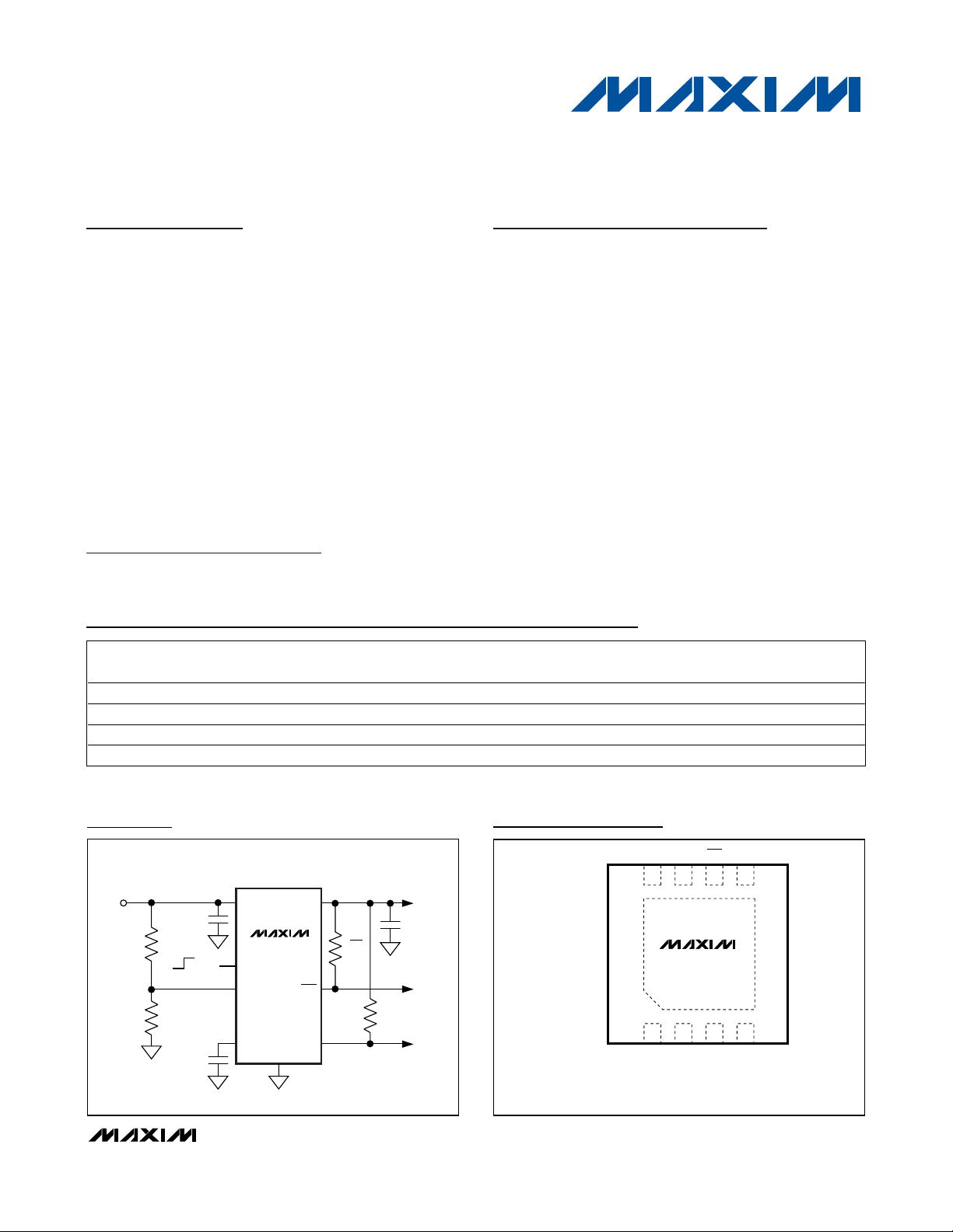
μC
RESET
CT
SI
+5V TO +28V
R
H
288kΩ
C
IN
10μF
C
CT
0.1μF
C
OUT
10μF
R
L
100kΩ
+5V (MAX5091A)/
+3.3V (MAX5091B)
100mA
SO
GND
EN
R
RES
10kΩ
V
OUT
RES
POWERFAIL
V
S
ON
OFF
V
IN
MAX5091
R
SO
10kΩ
Typical Application Circuit
19-0654; Rev 0; 11/06
For pricing, delivery, and ordering information, please contact Maxim/Dallas Direct! at
1-888-629-4642, or visit Maxim’s website at www.maxim-ic.com.
Note: All devices specified for -40°C to +125°C operating temperature range.
+Denotes lead-free package. *EP = Exposed paddle.
Pin Configurations continued at end of data sheet.
Automotive
Industrial
Home Security/Safety
Telecom/Networking
PART
MAX5091AATA+T 8 TDFN-8 5
MAX5091AASA+ 8 SO-EP* 5
MAX5091BATA+T 8 TDFN-8 3.3
MAX5091BASA+ 8 SO-EP* 3.3
PINPACKAGE
PRESET V
(V)
OUT
PKG
CODE
T833-2
S8E-14
T833-2
S8E-14
TOP
MARK
+APB
—
+APC
—
TOP VIEW
SO
V
OUT
8
+
134
V
S
(3mm x 3mm)
RES GND
7
MAX5091
EXPOSED PADDLE
2
EN CTSI
TDFN
65
MAX5091
28V, 100mA, Low-Quiescent-Current LDO
with Reset and Power-Fail Input/Output
2 _______________________________________________________________________________________
ABSOLUTE MAXIMUM RATINGS
ELECTRICAL CHARACTERISTICS (MAX5091A)
(VS= +14V, V
OUT
= 5V, EN unconnected, TA = TJ = -40°C to +125°C, C
IN
= 10µF, C
OUT
= 10µF, unless otherwise noted. Typical
specifications are at T
A
= +25°C.) (Note 1)
Stresses beyond those listed under “Absolute Maximum Ratings” may cause permanent damage to the device. These are stress ratings only, and functional
operation of the device at these or any other conditions beyond those indicated in the operational sections of the specifications is not implied. Exposure to
absolute maximum rating conditions for extended periods may affect device reliability.
VSto GND ..............................................................-0.3V to +28V
V
S
to GND (t ≤ 1s) ..................................................-0.3V to +40V
V
OUT
to GND ..........................................................-0.3V to +20V
V
S
to OUT ...............................................................-0.3V to +28V
RES, SO to GND.....................................................-0.3V to +20V
RES, SO Output Sink Current................................................5mA
V
OUT
Short Circuit (VS≤ 16V)………… ......................Continuous
EN, SI to GND.........................................................-0.3V to +12V
CT to GND.............................-0.3V to the lower of V
OUT
or +12V
Continuous Power Dissipation (T
A
= +70°C)
8-Pin SO-EP (derate 19.2mW/°C above +70°C) .........1538mW*
Thermal Resistance (θ
JA
)................................................52°C/W
Thermal Resistance (θ
JC
)..................................................6°C/W
8-Pin TDFN-EP (derate 24.4mW/°C above +70°C).....1951mW**
Thermal Resistance (θ
JA
)................................................41°C/W
Thermal Resistance (θ
JC
)...............................................8.3°C/W
Operating Junction Temperature Range...........-40°C to +125°C
Maximum Junction Temperature .....................................+150°C
Storage Temperature Range .............................-60°C to +150°C
Lead Temperature (soldering, 10s) .................................+300°C
)
)
*As per JEDEC51 Standard (single-layer board).
**As per JEDEC51 Standard (multilayer board).
PARAMETER SYMBOL CONDITIONS MIN TYP MAX UNITS
Output Voltage V
Dropout Voltage V
VS to V
OUT
Undervoltage
Line Regulation V
Load Regulation V
Current Limit I
Quiescent Current I
TA = +25°C, I
OUT
5.6V ≤ VS ≤ 28V, I
OUT
5.6V ≤ VS ≤ 40V, t ≤ 1s, I
(Note 2)
VS = +8V, I
= 1mA to 100mA 4.9 5 5.1
OUT
I
DP
VS = +4.75V
I
I
Difference in
V
OLO
LIM
VS = +4V, I
IO
+5.5V ≤ VS ≤ +28V, I
OL
1mA ≤ I
I
OUT
I
Q
OUT
I
OUT
= 35mA 0.4 V
OUT
≤ 100mA 17 50 mV
OUT
= 100µA 46 100
= 300µA 45 100
= 100mA 4.5 10 mA
= 1mA 4.95 5 5.05
OUT
OUT
OUT
OUT
= 1mA to 50mA (Note 2) 4.90 5 5.10
= 1mA to 30mA
OUT
4.9 5 5.1
= 10mA 0.1 0.25
= 50mA 0.2 0.4
= 100mA 0.3 0.5
= 1mA 0.6 5 mV
OUT
160 260 400 mA
V
V
µA
Shutdown Supply Current I
Thermal-Shutdown
Temperature
Thermal-Shutdown
Hysteresis
T
ΔT
SHDN
J(SHDN
J(SHDN
VEN ≤ +0.4V 17 30 µA
Temperature rising +165 °C
20 °C
MAX5091
28V, 100mA, Low-Quiescent-Current LDO
with Reset and Power-Fail Input/Output
_______________________________________________________________________________________ 3
ELECTRICAL CHARACTERISTICS (MAX5091A) (continued)
(VS= +14V, V
OUT
= 5V, EN unconnected, TA = TJ = -40°C to +125°C, C
IN
= 10µF, C
OUT
= 10µF, unless otherwise noted. Typical
specifications are at T
A
= +25°C.) (Note 1)
PARAMETER SYMBOL CONDITIONS MIN TYP MAX UNITS
RESET
Reset Threshold Voltage V
Reset Threshold
Hysteresis
Reset Pulse Delay t
RES Output Low Voltage V
RES Output High
Leakage Current
Delay Comparator
Threshold
Delay Comparator
Threshold Hysteresis
SENSE
Sense Threshold V
Sense Threshold
Hysteresis
Sense Output
Low Voltage
Sense Output
Leakage Current
Sense Input Current I
ENABLE
Enable Voltage V
Enable Internal
Pullup Current
RT
V
RTH
RD
RL
I
RH
V
CTTH
ST
V
SL
I
SH
SI
EN
I
EN
V
falling 85 90 94.5 %V
OUT
CCT = 100nF, tR ≥ 100µs 55 110 180 ms
VS ≥ +1.5V,R
V
= 5V 1.0 µA
RES
VCT rising 1.9 2.1 2.4 V
V
falling 1.10 1.16 1.24 V
SI
VSI ≤ 1.10V, VS ≥ 4V, RSO = 10kΩ to V
VSO = 5V, VSI ≥ 1.5V 1 µA
VSI = 3.3V -1 +1 µA
EN = high, regulator on 2.4
EN = low, regulator off 0.4
EN is internally pulled up to 3.6V (max) 3 µA
= 10kΩ to V
RES
OUT
OUT
30 65 100 mV
100 mV
50 100 150 mV
OUT
0.4 V
0.4 V
V
MAX5091
28V, 100mA, Low-Quiescent-Current LDO
with Reset and Power-Fail Input/Output
4 _______________________________________________________________________________________
ELECTRICAL CHARACTERISTICS (MAX5091B)
(VS= +14V, V
OUT
= 3.3V, EN unconnected, TA= TJ= -40°C to +125°C, C
IN
= 10µF, C
OUT
= 10µF, unless otherwise noted. Typical
specifications are at T
A
= +25°C.) (Note 1)
)
)
PARAMETER SYMBOL CONDITIONS MIN TYP MAX UNITS
Output Voltage V
VS to V
OUT
Undervoltage
Line Regulation V
Load Regulation V
Current Limit I
Quiescent Current I
Shutdown Supply
Current
Thermal-Shutdown
Temperature
Thermal-Shutdown
Hysteresis
RESET CIRCUIT
OUT
TA = +25°C, I
5V ≤ VS ≤ 28V, I
= 1mA 3.267 3.3 3.333
OUT
OUT
5V ≤ VS ≤ 40V, t < 1s, I
(Note 2)
Difference in
ΔT
T
J
V
IO
OL
OLO
LIM
Q
I
SHDN
( SHDN
J(SHDN
VS = +8V, I
VS = 3.5V, I
5V ≤ VS ≤ 28V, I
1mA ≤ I
I
= 100µA 45 100
OUT
I
= 300µA 45 100
OUT
I
= 100mA 4.4 10 mA
OUT
VEN ≤ 0.4V 17 30 µA
Temperature rising +165 °C
= 1mA to 100mA 3.234 3.3 3.366
OUT
= 35mA 0.2 0.4 V
OUT
OUT
≤ 100mA 11 40 mV
OUT
= 1mA to 50mA (Note 2) 3.234 3.3 3.366
= 1mA to 30mA
OUT
3.234 3.3 3.366
= 1mA 0.6 5 mV
160 260 400 mA
V
µA
20 °C
Reset Threshold Voltage V
Reset Threshold
Hysteresis
Reset Pulse Delay t
RES Output-Low Voltage V
RES Output-High
Leakage Current
Delay Comparator
Threshold
V
Delay Comparator
Threshold Hysteresis
RT
V
RTH
RD
RL
I
RH
CTTH
falling 85 90 94.5 %V
V
OUT
20 45 80 mV
CCT = 100nF, tR ≥ 100µs 55 105 180 ms
VS ≥ 1.5V, R
V
= 3.3V 1.0 µA
RES
= 4kΩ to V
RES
OUT
VCT rising 1.9 2.1 2.4 V
100 mV
OUT
0.4 V
MAX5091
28V, 100mA, Low-Quiescent-Current LDO
with Reset and Power-Fail Input/Output
_______________________________________________________________________________________ 5
Note 1: Limits at TA= -40°C are guaranteed by design and not production tested.
Note 2: Maximum output current is limited by the power dissipation capability of the package.
ELECTRICAL CHARACTERISTICS (MAX5091B) (continued)
(VS= +14V, V
OUT
= 3.3V, EN unconnected, TA= TJ= -40°C to +125°C, C
IN
= 10µF, C
OUT
= 10µF, unless otherwise noted. Typical
specifications are at T
A
= +25°C.) (Note 1)
Typical Operating Characteristics
(Typical Application Circuit, VS= +14V, CIN= 10µF, C
OUT
= 10µF, VSI= 0V, VEN= +2.4V, V
OUT
= +5V, TA= +25°C, unless other-
wise noted.)
OUTPUT VOLTAGE vs. INPUT VOLTAGE
MAX5091 toc01
VS (V)
V
OUT
(V)
10
5
15
3
4
5
6
2
0
MAX5091AV
OUT
AT NO LOAD, 100μA,
1mA, 10mA, 100mA
OUTPUT VOLTAGE vs. INPUT VOLTAGE
MAX5091 toc02
VS (V)
V
OUT
(V)
54321
1
2
3
4
0
06
MAX5091BV
OUT
AT NO LOAD, 100μA,
1mA, 10mA, 100mA
OUTPUT VOLTAGE vs. OUTPUT CURRENT
MAX5091 toc03
I
OUT
(mA)
V
OUT
(V)
1010.1
4.92
4.94
4.96
4.98
5.00
5.02
5.04
4.90
0.01 100
MAX5091A
VS = 14V
VS = 6V
PARAMETER SYMBOL CONDITIONS MIN TYP MAX UNITS
SENSE
Sense Threshold V
Sense Threshold
Hysteresis
Sense Output-Low
Voltage
Sense Output
Leakage Current
Sense Input Current I
ENABLE
Enable Voltage V
Enable Internal
Pullup Current
ST
V
SL
I
SH
SI
EN
I
EN
VSI falling 1.09 1.15 1.23 V
VSI ≤ 1.09V, VS ≥ 4V, RSO = 10kΩ to V
VSO = 3.3V, VSI ≥ 1.5V 1 µA
VSI = 3.3V -1 +1 µA
EN = high, regulator on 2.4
EN = low, regulator off 0.4
EN is internally pulled up to 3.6V (max) 3 µA
OUT
50 100 150 mV
0.4 V
V
MAX5091
28V, 100mA, Low-Quiescent-Current LDO
with Reset and Power-Fail Input/Output
6 _______________________________________________________________________________________
Typical Operating Characteristics (continued)
(Typical Application Circuit, VS= +14V, CIN= 10µF, C
OUT
= 10µF, VSI= 0V, VEN= +2.4V, V
OUT
= +5V, TA= +25°C, unless other-
wise noted.)
OUTPUT VOLTAGE
vs. TEMPERATURE
MAX5091 toc04
TEMPERATURE (°C)
V
OUT
(V)
11085603510-15
4.925
4.950
4.975
5.000
5.025
5.050
4.900
-40 135
MAX5091A
I
OUT
= 100μA
I
OUT
= 1mA
I
OUT
= 10mA
I
OUT
= 100mA
QUIESCENT CURRENT
vs. INPUT VOLTAGE
MAX5091 toc05
VS (V)
I
Q
(μA)
26221814106
10
100
1000
1
2303834
EN = OPEN
I
OUT
= NO LOAD
TA = +25°C, +85°C
TA = +125°C
TA = -40°C
QUIESCENT CURRENT
vs. INPUT VOLTAGE
MAX5091 toc06
VS (V)
I
Q
(μA)
26221814106
10
100
1000
1
2303834
EN = OPEN
I
OUT
= 100μA
TA = +25°C, +85°C
TA = +125°C
TA = -40°C
RESET OUTPUT LOW
vs. TEMPERATURE
MAX5091 toc07
TEMPERATURE (°C)
RESET OUTPUT LOW (V)
1109580655035205-10-25
0.05
0.10
0.15
0.20
0.25
0
-40 125
R
RES
= 4kΩ
R
RES
= 10kΩ
QUIESCENT CURRENT
vs. OUTPUT CURRENT
MAX5091 toc08
I
OUT
(mA)
I
Q
(mA)
110
0.1
1
10
0.01
0.1 100
VS = 14V
T
A
= +25°C
SHUTDOWN SUPPLY CURRENT
vs. INPUT VOLTAGE
MAX5091 toc09
VS (V)
I
SHDN
(μA)
302010
10
20
30
40
0
040
VS = 14V
T
A
= +25°C
EN = 0V
SHUTDOWN SUPPLY CURRENT
vs. TEMPERATURE
MAX5091 toc10
TEMPERATURE (°C)
I
SHDN
(μA)
10065-30-5
15
16
17
18
19
20
14
-40 135
VS = 14V
EN = 0V
DROPOUT VOLTAGE
vs. LOAD CURRENT
MAX5091 toc11
I
OUT
(mA)
DROPOUT VOLTAGE (mV)
101
25
50
75
100
125
150
175
200
225
250
275
300
325
0
0.1 100
MAX5091A
V
S
= 4.75V
DROPOUT VOLTAGE
vs. LOAD CURRENT
MAX5091 toc12
I
OUT
(mA)
DROPOUT VOLTAGE (mV)
101
25
50
75
100
125
150
175
200
225
250
275
300
0
0.1 100
MAX5091B
V
S
= 3.3V

MAX5091
28V, 100mA, Low-Quiescent-Current LDO
with Reset and Power-Fail Input/Output
_______________________________________________________________________________________ 7
Typical Operating Characteristics (continued)
(Typical Application Circuit, VS= +14V, CIN= 10µF, C
OUT
= 10µF, VSI= 0V, VEN= +2.4V, V
OUT
= +5V, TA= +25°C, unless other-
wise noted.)
DROPOUT VOLTAGE
vs. TEMPERATURE
400
MAX5091A
= 4.75V
V
S
350
300
250
200
150
DROPOUT VOLTAGE (mV)
100
50
0
-40 135
TEMPERATURE (°C)
I
I
OUT
OUT
= 100mA
= 10mA
SENSE THRESHOLD
vs. TEMPERATURE
1.50
1.45
1.40
1.35
1.30
1.25
1.20
1.15
SENSE THRESHOLD (V)
1.10
1.05
1.00
-40 135
SI INPUT RISING
SI INPUT FALLING
TEMPERATURE (°C)
10065-5 30
1006530-5
4.60
4.58
MAX5091 toc13
4.56
4.54
4.52
4.50
4.48
4.46
RESET THRESHOLD VOLTAGE (V)
4.44
4.42
4.40
-40 135
5
MAX5091 toc16
4
3
2
SENSE OUTPUT (V)
1
0
1.0 1.4
RESET THRESHOLD
vs. TEMPERATURE
MAX5091A
V
RISING
OUT
V
FALLING
OUT
1006530-5
TEMPERATURE (°C)
SENSE OUTPUT
vs. SENSE INPUT
VSI RISING
VSI FALLING
1.31.21.1
SENSE INPUT (V)
MAX5091 toc14
MAX5091 toc17
RESET VOLTAGE
vs. OUTPUT VOLTAGE
MAX5091A
5
= 10kΩ TO OUT
R
RES
4
(V)
3
RES
V
V
FALLING
OUT
2
1
0
4.3 4.7
V
OUT
V
(V)
POWER-SUPPLY REJECTION RATIO
vs. SUPPLY CURRENT
0
-10
-20
-30
-40
PSRR (dB)
-50
-60
-70
-80
0.01 100
FREQUENCY (kHz)
RISING
OUT
4.64.54.4
VIN = 14V
= 10mA
I
OUT
500mV
1010.1
MAX5091 toc15
MAX5091 toc18
P-P
LOAD-TRANSIENT RESPONSE
CIN = 10μF
= 10μF/10mΩ ESR
C
OUT
= 100μA TO 50mA
I
STEP
200μs/div
MAX5091 toc19
V
OUT
5V AC-COUPLED
100mV/div
50mA
I
OUT
20mA/div
100μA
LINE-TRANSIENT RESPONSE
200μs/div
MAX5091 toc20
V
OUT
5V AC-COUPLED
200mV/div
= 1mA
I
OUT
40V
V
S
10V/div
14V

MAX5091
28V, 100mA, Low-Quiescent-Current LDO
with Reset and Power-Fail Input/Output
8 _______________________________________________________________________________________
Pin Description
PIN
FUNCTION
1V
S
Regulator Input. Operating supply range is from +5V to +28V and withstands 40V transients. Bypass
V
S
to GND with a 10µF capacitor.
2SI
Voltage Sense/Power-Fail Comparator Input. SI is the noninverting input of an uncommitted comparator. SO
asserts low if V
SI
drops below the reference level, VST.
3EN
Enable Input. Leave unconnected (or pull EN high) to turn on the regulator. Pull EN low to place the device in
shutdown mode. EN is internally pulled up to 3.6V.
4CT
Reset Timeout Delay Capacitor Connection. Connect a capacitor from CT to GND to program the reset
timeout period/reset pulse delay. During regulation, CT is pulled up to V
OUT
. CT is pulled low during reset,
when EN is low, or when in thermal shutdown.
5 GND
Ground. Bypass the input and output capacitors to the GND plane. Solder to large pads or the circuit-board
ground plane to maximize thermal dissipation.
6 RES
Active-Low Reset Output. Pull up externally to V
OUT
. Open-drain RES goes low when V
OUT
is below the reset
threshold. Once output voltage is in regulation, RES goes high after the programmed reset timeout period is
over. RES is low when EN is low or in thermal shutdown.
7SO
Voltage Sense/Power-Fail Comparator Output. Pull up externally to V
OUT
. Open-drain SO asserts
low when V
SI
drops below the reference level, VST. SO also asserts low when EN is low or in thermal
shutdown.
8
Regulator Output. Fixed at +5V (MAX5091A) or +3.3V (MAX5091B). Bypass with a 10µF ceramic capacitor to
GND.
EP EP
E xp osed P ad d l e. E P i s i nter nal l y connected to GN D . C onnect E P to GN D to p r ovi d e a l ow ther m al - r esi stance
p ath fr om the IC j uncti on to the P C b oar d . D o not use as the onl y el ectr i cal connecti on to G N D .
Typical Operating Characteristics (continued)
(Typical Application Circuit, VS= +14V, CIN= 10µF, C
OUT
= 10µF, VSI= 0V, VEN= +2.4V, V
OUT
= +5V, TA= +25°C, unless other-
wise noted.)
V
OUT
STARTUP RESPONSE
MAX5091 toc21
10ms/div
V
OUT
2V/div
V
S
5V/div
0V
0V
I
OUT
= 10mA
ENABLE RESPONSE
MAX5091 toc22
200μs/div
V
OUT
5V/div
EN
5V/div
0V
0V
I
OUT
= 100mA
SHUTDOWN RESPONSE
MAX5091 toc23
200μs/div
V
OUT
2V/div
EN
2V/div
0V
0V
I
OUT
= 100mA
NAME
V
OUT

MAX5091
28V, 100mA, Low-Quiescent-Current LDO
with Reset and Power-Fail Input/Output
_______________________________________________________________________________________ 9
Figure 1. Functional Diagram
LDO
ENABLE
V
REF
1.25V
PASS
ELEMENT
0.9 x V
REF
V
OUT
MAX5091
V
REF
GND
V
OUT
I
CT
2μA
N
V
REF
2.1V
V
REF
DELAY
COMPARATOR
FAULT
DETECTION
(TEMP AND SC)
RES
N
SCLIM
SD
SO
N
V
S
V
INT
3μA
MAX
EN
PREREGULATOR
ALWAYS-ON
CT
SI
ALWAYS-ON
V
INT
3.6V (MAX)

MAX5091
28V, 100mA, Low-Quiescent-Current LDO
with Reset and Power-Fail Input/Output
10 ______________________________________________________________________________________
Detailed Description
Regulator
The MAX5091 high-voltage, LDO regulator operates
from +5V to +28V input voltage. The device withstands
up to 40V transients, providing protection against temporary overvoltage conditions like load dump. The
MAX5091 incorporates internal feedback resistors for
factory-preset voltages of either +5V (MAX5091A) or
+3.3V (MAX5091B). The regulator is capable of driving
up to 100mA of load current and features a typical current limit of 260mA. The regulator uses a pnp pass element and provides low 0.5V dropout while delivering
100mA load current. The output of the regulator follows
closely to the input during turn-on. See the Output
Voltage vs. Input Voltage graph in the Typical
Operating Characteristics. This makes the usable input
voltage range for 3.3V and 5V output down to 3.7V and
5.5V, respectively. The MAX5091 is designed to operate with very low quiescent current during always-on
operation when not in dropout. The regulator is stable
with a wide variety of capacitors including low-ESR
ceramic 10µF (0603 case size). The load-transient
response curves depict the stability of the LDO when
using different capacitance and ESR ranges. See the
Capacitor Selection and Regulator Stability section in
the Applications Information.
Reset Output (
RES
)
The MAX5091 integrates a power-on-reset circuit. RES
is an open-drain output that requires a pullup resistor to
V
OUT
. The open-drain MOSFET can sink up to 825µA
current while keeping the RES voltage below 0.4V. The
internal reset circuit monitors the regulator output voltage and RES asserts an active-low output when the
regulator output falls below a reset threshold of typically 0.9 x V
OUT
. The RES output remains low when V
OUT
is below the reset threshold, and remains low for the
duration of the reset timeout period (tRD). The reset
timeout period is programmable and can be set with an
external capacitor connected from CT to ground. The
duration of the delay as a function of CT is:
The default reset timeout period is 35µs when no
capacitor is connected from CT to ground.
SI/SO Comparator
The MAX5091 includes an uncommitted comparator for
monitoring the input voltage or for detecting power-fail
conditions. The input SI is the noninverting input of the
comparator. The open-drain output SO asserts low
when voltage at the input SI drops below the threshold
voltage, V
ST
(see Figure 1). The sense comparator typically has a hysteresis of 100mV. Use the following
equation to calculate the resistor-divider for programming the trip voltage (V
TRIP
) during power-fail. See the
Typical Application Circuit.
where V
ST
= 1.16V (typ). Choose RLbetween 100kΩ to
300kΩ.
Enable Input
The enable (EN) is a TTL-compatible logic input. Logic
low at EN turns off the regulator and reduces the current consumption to 17µA (typ). It is internally pulled up
to a logic-high voltage (3.6V max) by an internal resistor. Thus, the MAX5091 is enabled by default when V
S
is applied and EN is left unconnected. The regulator,
reset supervisor circuit, and the sense comparator can
be manually shut down by pulling EN low. For shutdown operation, the pulldown network must be capable
of sinking 3µA max, since the internal pullup resistor
sets the maximum pullup current at 3µA. The external
pulldown device should not leak more than 1µA current
when it is in the off-state.
Current Limit
The MAX5091 features a current limiter that monitors
the output current and controls the pass transistor’s
gate voltage, limiting the output current to typically
260mA. The output can be continuously shorted to
ground without damaging the device at VS≤ 16V. Note
that the output short-circuit current may increase the
power dissipation significantly and raise the junction
temperature to its thermal-shutdown threshold. In such
a case, the MAX5091 is temporarily turned off.
Thermal Shutdown
When the junction temperature exceeds TJ= +165°C
(typ), an internal thermal sensor signals the shutdown
logic to turn off the pass transistor and allow the IC to
cool. The thermal sensor turns the pass transistor on
again after the IC’s junction temperature cools by
+20°C (typ), resulting in a cycled output during continuous thermal-overload conditions. Thermal shutdown
protects the MAX5091 in the event of fault conditions.
For continuous operation, do not exceed the absolute
maximum junction temperature of TJ= +150°C.
V
(V R )
TRIP
ST H
=
×+
RV
L
ST
t
CV
I
I
RD
CT CCTH
CT
CT
=
×
+×
==×
−
−
( )
. .
35 10
21 2 10
6
6
where V V and A
CCTH

MAX5091
28V, 100mA, Low-Quiescent-Current LDO
with Reset and Power-Fail Input/Output
______________________________________________________________________________________ 11
Applications Information
Available Output Current Calculation
The MAX5091 high-voltage regulator provides up to
100mA of output current. The input voltage extends to
+28V. Package power dissipation limits the amount of
output current available for a given input/output voltage
and ambient temperature. Figure 2 depicts the maximum power dissipation curve for the 8-pin SO-EP package. The graph assumes that the exposed metal back
of the MAX5091 package is soldered to copper on a
single layer PCB according to the JEDEC51 standard.
Use Figure 2 to determine the allowable package dissipation for a given ambient temperature. Alternately, use
the following formula to calculate the allowable package dissipation:
After determining the allowable package dissipation, calculate the maximum output current using the following
formula:
The above equations do not include the power dissipation
from self-heating due to the IC ground current.
The junction-to-ambient thermal impedance depends
on the area of the copper plane, its thickness, and the
number of copper layers on PCB. For the higher power
dissipation requirement, use multiple-layered PCBs
with 2oz copper and a large copper area.
Capacitor Selection and
Regulator Stability
For stable operation over the full temperature range and
with load currents up to 100mA, use a 10µF output
capacitor with a low ESR. Table 1 shows a list of recommended output capacitor ESR for various load conditions.
I
P
VV
OUT(MAX)
D
S OUT
≅−
P
1.538W For T 70 C
1.538 0.01923 T C For 70 C T 125 C
D
A
AA
()
=
≤+ °
−−+<≤+°
⎧
⎨
⎩
°°
70
Figure 2. 8-Pin SO-EP Maximum Power Dissipation vs.
Temperature
Table 1. Recommended Output Capacitor
ESR
(W)
D
P
2.0
1.8
1.6
1.4
1.2
1.0
0.8
0.6
0.4
0.2
1.538W
0
20
TEMPERATURE (°C)
8-PIN SO-EP
DERATE
19.23mW/°C
130
1103040506070809010
120100
140
MAX5091 fig02
150
I
OUT
I
≤ 10mA C
OUT
I
≤ 50mA C
OUT
I
≤ 100mA C
OUT
RECOMMENDED C
V
= 3.3V V
OUT
< 0.66Ω C
ESR
< 0.132Ω C
ESR
< 66mΩ C
ESR
OUT
ESR
OUT
ESR
ESR
ESR
= 5.0V
< 1Ω
< 0.2Ω
< 0.1Ω

MAX5091
28V, 100mA, Low-Quiescent-Current LDO
with Reset and Power-Fail Input/Output
12 ______________________________________________________________________________________
Chip Information
PROCESS: BiCMOS
RES
GND
EXPOSED PADDLE
CT
1
+
2
87V
OUT
SOSI
EN
V
S
SO-EP
TOP VIEW
3
4
6
5
MAX5091
Pin Configurations (continued)

MAX5091
28V, 100mA, Low-Quiescent-Current LDO
with Reset and Power-Fail Input/Output
______________________________________________________________________________________ 13
Package Information
(The package drawing(s) in this data sheet may not reflect the most current specifications. For the latest package outline information,
go to www.maxim-ic.com/packages
.)
8L, SOIC EXP. PAD.EPS
PACKAGE OUTLINE
8L SOIC, .150" EXPOSED PAD
21-0111
1
C
1

MAX5091
28V, 100mA, Low-Quiescent-Current LDO
with Reset and Power-Fail Input/Output
14 ______________________________________________________________________________________
Package Information (continued)
(The package drawing(s) in this data sheet may not reflect the most current specifications. For the latest package outline information,
go to www.maxim-ic.com/packages
.)
6, 8, &10L, DFN THIN.EPS
PACKAGE OUTLINE, 6,8,10 & 14L,
TDFN, EXPOSED PAD, 3x3x0.80 mm
21-0137
1
H
2

MAX5091
28V, 100mA, Low-Quiescent-Current LDO
with Reset and Power-Fail Input/Output
Maxim cannot assume responsibility for use of any circuitry other than circuitry entirely embodied in a Maxim product. No circuit patent licenses are
implied. Maxim reserves the right to change the circuitry and specifications without notice at any time.
Maxim Integrated Products, 120 San Gabriel Drive, Sunnyvale, CA 94086 408-737-7600 ____________________ 15
© 2006 Maxim Integrated Products is a registered trademark of Maxim Integrated Products, Inc.
Heaney
Package Information (continued)
(The package drawing(s) in this data sheet may not reflect the most current specifications. For the latest package outline information,
go to www.maxim-ic.com/packages
.)
COMMON DIMENSIONS
SYMBOL
MIN. MAX.
A 0.70 0.80
D 2.90 3.10
E 2.90 3.10
0.00 0.05
A1
L 0.20 0.40
0.25 MIN.k
A2 0.20 REF.
PACKAGE VARIATIONS
PKG. CODE N D2 E2 e JEDEC SPEC b [(N/2)-1] x e
2.30±0.101.50±0.106T633-1 0.95 BSC MO229 / WEEA 1.90 REF0.40±0.05
T633-2 6 1.50±0.10 2.30±0.10
1.50±0.10
T833-2 8 1.50±0.10 2.30±0.10 0.65 BSC MO229 / WEEC 0.30±0.05 1.95 REF
T833-3 8 1.50±0.10 2.30±0.10 0.65 BSC MO229 / WEEC 0.30±0.05 1.95 REF
1.50±0.10
1.50±0.1010T1033-2
2.30±0.10
0.95 BSC MO229 / WEEA
MO229 / WEEC
MO229 / WEED-3
0.50 BSC
0.40 BSC - - - - 0.20±0.05 2.40 REFT1433-2 14 2.30±0.101.70±0.10
MO229 / WEED-3
0.40±0.05 1.90 REF
1.95 REF0.30±0.050.65 BSC2.30±0.108T833-1
2.00 REF0.25±0.050.50 BSC2.30±0.1010T1033-1
2.00 REF0.25±0.05
2.40 REF0.20±0.05- - - - 0.40 BSC1.70±0.10 2.30±0.1014T1433-1
PACKAGE OUTLINE, 6,8,10 & 14L,
TDFN, EXPOSED PAD, 3x3x0.80 mm
-DRAWING NOT TO SCALE-
21-0137
2
H
2
 Loading...