

19-1143; Rev 0; 10/96
EVALUATION KIT
AVAILABLE
Quad/Triple, SPDT, RGB Switches
with 250MHz Video Buffer Amplifiers
_______________General Description
The MAX498/MAX499 are high-speed, quad/triple, single-pole/double-throw video switches with on-board
closed-loop buffer amplifiers. The buffer amplifiers feature +6dB gain (A
= 2V/V), 250MHz -3dB band-
VCL
width, 70MHz 0.1dB gain flatness, and 1250V/µs slew
rate. Fast switching time (3ns) and fast settling time
(12ns for a 4V step) make these devices excellent
choices for a wide variety of video applications. The low
differential gain/phase errors (0.03%/0.06°) and wide
bandwidth make them ideal for both composite-video
and RGB applications. The amplifiers are capable of
delivering ±2.5V into back-terminated 50Ω or 75Ω
cables, and they deliver ±2V to a 75Ω load, allowing
multiple cables to be driven from a single output.
For implementation of large switch arrays, a low-power
disable mode places the amplifier outputs in a highimpedance state. Channel selection and output
enable/disable are controlled by four TTL/CMOScompatible logic inputs. Each video input is isolated by
an AC-ground pin, which minimizes channel-to-channel
capacitance and reduces crosstalk to 90dB at 10MHz.
The four-channel MAX498 dissipates 390mW (typical)
from ±5VDC power supplies with all output buffers
enabled. Power consumption is reduced to 130mW with
all buffers disabled. The corresponding dissipation for
the three-channel MAX499 is 300mW enabled and
100mW disabled.
________________________Applications
Video Switching and Routing
Broadcast-Quality Composite-Video Multiplexing
Workstations
Video Editing
Broadcast and High-Definition TV Systems
Multimedia Products
Medical Imaging
____________________________Features
♦ High Speed:
250MHz Small-Signal -3dB Bandwidth
135MHz Full-Power -3dB Bandwidth
♦ 70MHz 0.1dB Gain Flatness
♦ 1250V/µs Slew Rate
♦ 12ns to 0.1% Settling Time
♦ 0.03°/0.06% Differential Phase/Gain Error
♦ 2pF Input Capacitance
♦ 3ns Channel-Switching Time
♦ 120mVp-p Channel-Switching Transient
♦ Three-State Output Allows Large Switch Arrays
♦ Directly Drives 50Ω or 75Ω Back-Terminated
Cables
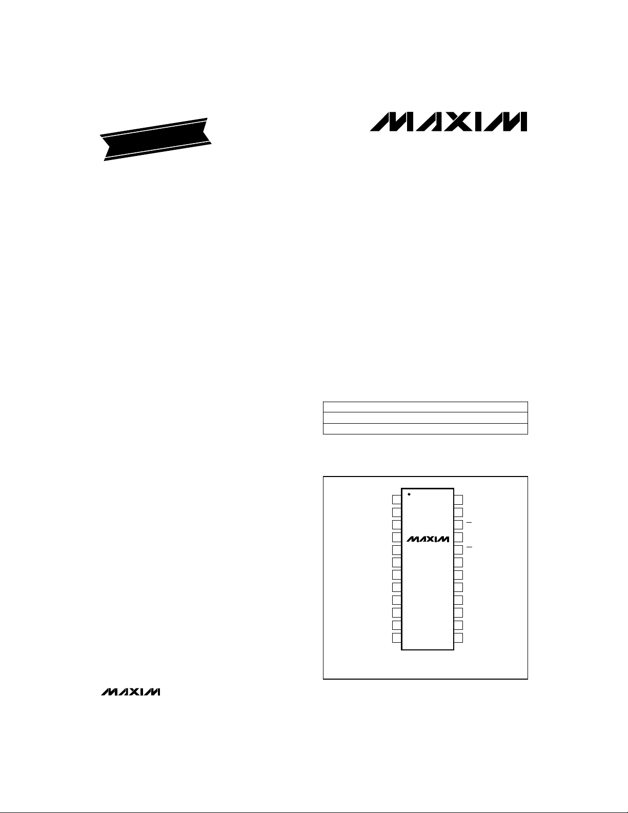
______________Ordering Information
PART
MAX498CWI
MAX499CWG
TEMP. RANGE PIN-PACKAGE
0°C to +70°C
0°C to +70°C
28 SO
24 SO
_________________Pin Configurations
TOP VIEW
MAX498 appears at end of data sheet.
IN1A
GND
IN2A
GND
IN3A
V
IN1B
GND
IN2B
GND
IN3B
1
2
3
4
MAX499
5
6
CC
V
7
EE
8
9
10
11
12
SO
GND
24
23
LE
22
EN
21
A0
20
CS
OUT1
19
V
18
CC
V
17
EE
OUT2
16
N.C.
15
OUT3
14
N.C.
13
MAX498/MAX499
________________________________________________________________
Maxim Integrated Products
1
For free samples & the latest literature: http://www.maxim-ic.com, or phone 1-800-998-8800
Quad/Triple, SPDT, RGB Switches
with 250MHz Video Buffer Amplifiers
ABSOLUTE MAXIMUM RATINGS
Supply Voltage (VCCto VEE)................................................+12V
Voltage on IN__ to GND..................(V
Voltage on Digital Inputs
(LE, EN, A0, CS).........................................-0.3V to (V
Voltage on OUT_ (disabled)..................................................±4V
Output Short-Circuit Duration
to -4V ≤ OUT_ ≤ +4V ..................................................Continuous
Stresses beyond those listed under “Absolute Maximum Ratings” may cause permanent damage to the device. These are stress ratings only, and functional
operation of the device at these or any other conditions beyond those indicated in the operational sections of the specifications is not implied. Exposure to
absolute maximum rating conditions for extended periods may affect device reliability.
- 0.3V) to (VCC+ 0.3V)
EE
CC
+ 0.3V)
Continuous Power Dissipation (T
24-Pin SO (derate 11.76mW/°C above +70°C).............941mW
28-Pin SO (derate 12.5mW/°C above +70°C)......................1W
Operating Temperature Range .................................0°C to +70°
Storage Temperature Range.............................-65°C to +150°C
Lead Temperature (soldering, 10sec).............................+300°C
DC ELECTRICAL CHARACTERISTICS
(VCC= +5V, VEE= -5V, VIN__ = 0V, RL= 150Ω, LE = EN = CS = 0V, TA= 0°C to +70°C, unless otherwise noted. Typical values are at
= +25°C.)
T
A
MAX498/MAX499
Input Voltage Range
Voltage Gain
Input Offset Voltage
Input Offset Voltage Drift
Input Bias Current
Input Resistance
Input Capacitance
Output Short-Circuit Current
Output Current ±27 ±40
On Output Resistance
Negative Power-Supply
Rejection
Logic Low Voltage
Logic High Voltage
Logic Input Current
Positive Supply Current
Negative Supply Current
Note 1: Limited by package power dissipation.
2 _______________________________________________________________________________________
IN
A
V
OS
OS
B
IN
IN
OUT(SC)
OUT_
OUT
INLL
INLH
INL
I
CC
I
EE
RL= 150Ω, -1.25V ≤ VIN≤ +1.25V
RL= 75Ω, -1.0V ≤ VIN≤ +1.0V
-1.25V ≤ VIN≤ +1.25V
Channel on or off
-3.5V ≤ OUT_ ≤ +3.5V (Note 1)
-2.0V ≤ V
f = 10MHz
-2.50V ≤ V
4.50V ≤ VCC≤ 5.50V, VEE= -5.0V
-5.50V ≤ VEE≤ -4.5V, VCC= +5.0V
0V ≤ V
INL
EN = 0
EN = 1
EN = 0
EN = 1
CONDITIONS
≤ +2.0V, RL= 75Ω
OUT_
≤ +2.50V
OUT
≤ V
CC
MAX498
MAX499 31 41
MAX498
MAX499
MAX498
MAX499
MAX498
MAX499
= +70°C)
A
1.985 2.030
1.965 2.030
40 52
14 17
11 14
38 50
29 39
12 15
912
UNITSMIN TYP MAXSYMBOLPARAMETER
µV/°C±50TCV
V±1.25 ±1.70V
V/V
mV±2 ±9V
µA±1 ±7I
kΩ200 700R
pF2C
mA120I
mAI
Ω0.15R
Ω3.0On Output Impedance
kΩ1.0 1.2Off Output Resistance
V±4.50 ±5.50Operating Supply-Voltage Range
dB55 72PSR+Positive Power-Supply Rejection
dB55 72PSR-
V0.8V
V2V
µA-10 130I
mA
mA

Quad/Triple, SPDT, RGB Switches
with 250MHz Video Buffer Amplifiers
AC ELECTRICAL CHARACTERISTICS
(VCC= +5V, VEE= -5V, V
Small-Signal, -3dB Bandwidth
Settling Time
= 0V, RL= 100Ω, LE = EN = CS = 0V, TA= +25°C, unless otherwise noted.)
IN__
CONDITIONS
VIN≤ 100mVp-p MHz250BW
-3dB
VIN≤ 100mVp-p MHz70±0.1dB Gain Flatness
V
= ±2V MHz135FPBWFull-Power, -3dB Bandwidth
OUT
V
= 4V step V/µs1250SRSlew Rate
OUT
0.1%, V
s
f = 100kHz
f = 100kHz
f = 10MHz
fC= 3MHz
f = 10MHz (Note 2)
f = 10MHz (Note 3)
EN = 1, f = 10MHz (Note 4)
f = 3.58MHz (Note 5), RL= 150Ω
f = 3.58MHz (Note 5), RL= 150Ω
OUT
= 4V step ns12t
UNITSMIN TYP MAXSYMBOLPARAMETER
7.8Input Voltage Noise Density
2.6Input Current Noise Density
0.06Diff PhaseDifferential Phase
nV/√Hz
pA/√Hz
dB-50THDTotal Harmonic Distortion
dBc-66SFDRSpurious-Free Dynamic Range
dB90Adjacent-Channel Crosstalk
dB62All-Hostile Crosstalk
dB81Off-Isolation
%0.03Diff GainDifferential Gain
degrees
TIMING CHARACTERISTICS
(VCC= +5V, VEE= -5V, V
otherwise noted.)
A0/EN to CS Setup Time
A0/EN to CS Hold Time
CS Pulse Width
Channel-Switching
Propagation Delay
Channel-Switching Time
Channel-Switching Transient
Enable/Disable Switching
Transient
Amplifier-Disable Time
Amplifier-Enable Time
Note 2: Test-channel input grounded through a 50Ω resistor. Adjacent channel driven to a 2Vp-p output with a 10MHz sine wave
Note 3: Same as Note 2, except all channels but the test channel are driven to a 2Vp-p output with a 10MHz sine wave (Figure 9).
Note 4: Test-channel input connected to a 2V
Note 5: Input test signal is a 3.58MHz sine wave of 40IRE amplitude, superimposed on a 0IRE to 100IRE linear ramp (Figure 10).
Note 6: Guaranteed by design.
Note 7: V
Note 8: V
Note 9: Delay from EN to 90% of V
Note 10: Delay from EN to 10% of V
(Figure 9).
disabled (Figure 9).
= +1V, V
INA
= +1V, V
INA
= 0V, RL= 150Ω, LE = EN = CS = 0V, TA= 0°C to +70°C. Typical values are at TA= +25°C, unless
IN_ _
CONDITIONS
LE = high (Note 6)
SU
LE = high (Note 6)
H
(Note 6)
CS
(Note 7)
PD
(Note 8)
SW
V
INA
V
INA
(Note 9) 16 nst
OFF
(Note 10) 24 nst
ON
p-p
= -1V, delay from CS to 10% of V
INB
= -1V, delay from CS to 10% of V
INB
OUT.
OUT.
= V
= 0V
INB
= V
= 0V
INB
sine wave at 10MHz. The test channel’s output is measured with the outputs
OUT.
OUT.
Positive
Negative 50
Positive
Negative
70
10
150
UNITSMIN TYP MAXSYMBOLPARAMETER
ns8t
ns4t
ns15t
ns20t
ns3t
mV
mV
MAX498/MAX499
_______________________________________________________________________________________ 3
Quad/Triple, SPDT, RGB Switches
with 250MHz Video Buffer Amplifiers
__________________________________________Typical Operating Characteristics
(VCC= +5V, VEE= -5V, RL= 100Ω, TA = +25°C, unless otherwise noted.)
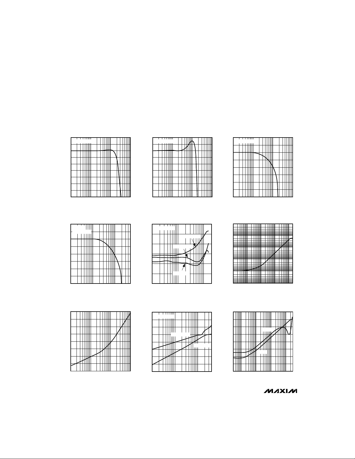
SMALL-SIGNAL GAIN
V
= 20mVp-p
IN
LARGE-SIGNAL GAIN
RL = 50Ω
= 2Vp-p
V
OUT
vs. FREQUENCY
100M
FREQUENCY (Hz)
vs. FREQUENCY
100M
FREQUENCY (Hz)
8
7
6
5
4
3
GAIN (dB)
2
1
MAX498/MAX499
0
-1
1M 10M 1G
8
7
6
5
4
GAIN (dB)
3
2
1
0
1M 10M 500M
MAX498/499-01
MAX498/499-04
GAIN (dB)
GAIN FLATNESS
V
= 20mVp-p
IN
LARGE-SIGNAL GAIN
vs. FREQUENCY
V
= 2Vp-p
OUT
vs. FREQUENCY
100M
FREQUENCY (Hz)
OUT0–OUT1
OUT0–OUT3
OUT0–OUT2
FREQUENCY (Hz)
6.2
6.1
6.0
5.9
5.8
5.7
GAIN (dB)
5.6
5.5
5.4
5.3
1M 10M 1G
0.14
0.10
0.06
0.02
-0.02
-0.06
-0.10
1M 10M
100M
LARGE-SIGNAL GAIN
8
7
MAX498/499-02
6
5
4
GAIN (dB)
3
2
1
0
1M 10M 1G
1000
MAX498/499-05
100
10
1
IMPEDANCE (Ω)
0.1
0.01
10k 100k 1M 10M 100M
vs. FREQUENCY
V
= 2Vp-p
OUT
FREQUENCY (Hz)
OUTPUT IMPEDANCE
vs. FREQUENCY
FREQUENCY (Hz)
MAX498/499-03
100M
MAX498/499 TOC-06
OFF-ISOLATION
-20
-30
-40
-50
-60
-70
OFF-ISOLATION (dB)
-80
-90
-100
1M 10M 1G
vs. FREQUENCY
100M
FREQUENCY (Hz)
MAX498/499-07
CROSSTALK (dB)
-100
-120
-140
20
= 2Vp-p
V
OUT
0
-20
-40
-60
-80
1M 10M
CROSSTALK
vs. FREQUENCY
ALL HOSTILE
FREQUENCY (Hz)
ADJACENT
100M
MAX498/499-08
PSR (dB)
POWER-SUPPLY REJECTION
-15
-25
-35
-45
-55
-65
-75
-85
-95
vs. FREQUENCY
1M0.1M30k 10M
FREQUENCY (Hz)
4 _______________________________________________________________________________________
MAX498/499-09
PSR-
PSR+
100M
Quad/Triple, SPDT, RGB Switches
with 250MHz Video Buffer Amplifiers
____________________________Typical Operating Characteristics (continued)
(VCC= +5V, VEE= -5V, RL= 100Ω, TA = +25°C, unless otherwise noted.)
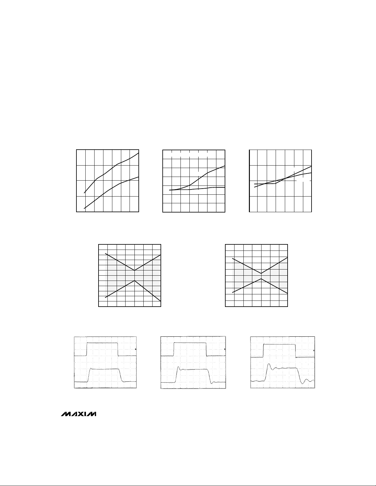
MAX498
SUPPLY CURRENT
50
45
40
SUPPLY CURRENT (mA)
35
30
vs. TEMPERATURE
I
CC
I
EE
-55 -35 -15 5 25 45 65 85
TEMPERATURE (°C)
INPUT OFFSET VOLTAGE
vs. TEMPERATURE
-55-35-15 5 25 45 65 85
(mV)
OS
V
12
10
8
6
4
2
0
-2
-4
-6
-8
-10
-12
MAX498/499-10
CURRENT (mA)
TEMPERATURE (°C)
DISABLED SUPPLY CURRENT
15
14
13
12
11
10
9
8
-55-35-15 5 25 45 65 85
vs. TEMPERATURE
EN = HIGH (OUTPUTS DISABLED)
I
CC
I
EE
TEMPERATURE (°C)
MAX498/499-13
2.0200
MAX498/499-11
2.0175
2.0150
SUPPLY CURRENT (mA)
2.0125
2.0100
INPUT BIAS CURRENT
10
8
6
4
2
0
-2
-4
INPUT BIAS CURRENT (µA)
-6
-8
-10
vs. TEMPERATURE
-55-35-15 5 25 45 65 85
TEMPERATURE (°C)
GAIN vs. TEMPERATURE
-55 -35 -15 5 25 45 65 85
V
IN
TEMPERATURE (°C)
= +1V
MAX498/499-14
V
= -1V
IN
MAX498/MAX499
MAX498/499-12
+1
0
IN
-1
+2
VOLTAGE (V)
OUT
0
-2
LARGE-SIGNAL
PULSE RESPONSE
TIME (10ns/div)
MAX498/499 TOC-16
VOLTAGE (V)
OUT
+1
0
IN
-1
+2
0
-2
LARGE-SIGNAL
PULSE RESPONSE (C
TIME (10ns/div)
= 47pF)
L
MAX498/499 TOC-17
VOLTAGE (V)
OUT
+1
0
IN
-1
+2
0
-2
LARGE-SIGNAL
PULSE RESPONSE (C
TIME (10ns/div)
L
_______________________________________________________________________________________
= 100pF)
MAX498/499 TOC-18
5

Quad/Triple, SPDT, RGB Switches
with 250MHz Video Buffer Amplifiers
____________________________Typical Operating Characteristics (continued)
(VCC= +5V, VEE= -5V, RL= 100Ω, TA = +25°C, unless otherwise noted.)
SMALL-SIGNAL
PULSE RESPONSE
+100
IN
0
-100
+200
VOLTAGE (mV)
0
OUT
-200
MAX498/MAX499
TIME (10ns/div)
CHANNEL SWITCHING
+2
OUT_
0
-2
+5
VOLTAGE (V)
A0
0
TIME (10ns/div)
IN_A = -1V
IN_B = +1V
ENABLE/DISABLE
SWITCHING TRANSIENT
+5
ENABLE
0
+100m
0
OUT_
VOLTAGE (V)
-100m
TIME 50ns/div
MAX498/499 TOC-19
VOLTAGE (mV)
OUT
MAX498/499 TOC-22
VOLTAGE (V)
ENABLE
IN
+100
0
-100
+200
0
-200
+2
OUT
0
+5
0
SMALL-SIGNAL
PULSE RESPONSE (C
TIME (10ns/div)
ENABLE/DISABLE
SWITCHING
TIME (10ns/div)
MAX498/499 TOC-25
= 47pF)
L
SMALL-SIGNAL
PULSE RESPONSE (C
+100
IN
MAX498/499 TOC-20
MAX498/499 TOC-23
300
280
260
240
220
200
180
BANDWIDTH (MHz)
160
140
120
0.01 0.1 10
0
-100
+200
VOLTAGE (mV)
OUT
0
-200
+5
A0
0
+100m
VOLTAGE (V)
OUT_
0
-100m
vs. INPUT VOLTAGE
INPUT VOLTAGE (Vp-p)
CHANNEL-SWITCHING
BANDWIDTH
TIME (10ns/div)
TRANSIENT
TIME (50ns/div)
1
= 100pF)
L
MAX498/499-26
MAX498/499 TOC-21
MAX498/499 TOC-24
6 _______________________________________________________________________________________

Quad/Triple, SPDT, RGB Switches
with 250MHz Video Buffer Amplifiers
______________________________________________________________Pin Description
PIN
MAX498
1, 3, 5,
11, 13,
7, 22 V
9, 21 V
15, 17 N.C. No Connect. Not internally connected; connect to GND.
MAX499
2, 4, 9,
19
10 IN1B Signal Input 1, Channel B
12 IN2B Signal Input 2, Channel B
14 IN3B Signal Input 3, Channel B
16 OUT3 Output 3
18 OUT2 Output 2
20 OUT1 Output 1
23 OUT0 Output 0
24
25 A0
26
27 LE
28 IN0A Signal Input 0, Channel A
11, 24
2 IN1A Signal Input 1, Channel A
4 IN2A Signal Input 2, Channel A
6 IN3A Signal Input 3, Channel A
6, 18
8 IN0B Signal Input 0, Channel B
7, 17
10
12
13, 15
14
16
19
20
21
22
23
NAME FUNCTION
GND
1
3
5
—
8
—
—
Analog Ground. All ground pins are internally connected. Connect all ground pins externally to
ground to minimize impedance.
Positive Power-Supply Voltage. Connect VCCto +5V. VCCpins are internally connected.
Connect both pins externally to +5V to minimize supply impedance. Bypass each pin to
CC
ground with a 0.1µF ceramic capacitor.
Negative Power-Supply Voltage. Connect VEEto -5V. VEEpins are internally connected.
Connect both pins to -5V externally to minimize supply impedance. Bypass each pin to
EE
ground with a 0.1µF ceramic capacitor.
Chip-Select Input. When CS is low, the A0 and EN latches are transparent. The data present at A0
CS
is latched when CS goes high. LE’s status determines whether EN is latched along with A0, or if the
EN latch remains transparent independently of CS.
Address Input. A0 = 0 selects channel A, and A0 = 1 selects channel B if CS is low. A0 is
latched on CS’s low-to-high transition.
Output Buffer-Enable Input. EN = 0 enables the output buffer amplifiers, and EN = 1 disables
EN
the output buffers if CS is low. EN is latched during CS’s low-to-high transition if LE is high. EN
is not latched if LE is low.
Latch-Enable Input. With LE = 1, EN is latched along with A0 when CS goes high. When LE = 0,
the EN latch is transparent independently of CS’s state.
MAX498/MAX499
_______________________________________________________________________________________ 7

Quad/Triple, SPDT, RGB Switches
with 250MHz Video Buffer Amplifiers
MAX498/MAX499
+5V
DC
10µF
-5V
DC
10µF
0.1µF
0.1µF
1
GND
2
IN1A
3
GND
4
IN2A
5
GND
6
IN3A
7
V
CC
8
IN0B
9
V
EE
10
IN1B
MAX498
IN0A
OUT0
V
OUT1
GND
28
27
LE
26
EN
25
A0
24
CS
23
22
CC
21
V
EE
20
19
0.1µF
0.1µF
+5V
-5V
DC
DC
11
GND
12
IN2B
13
GND
14
IN3B
EIGHT-IN/FOUR-OUT
VIDEO MUX AMP
18
OUT2
17
N.C.
16
OUT3
15
N.C.
NOTE: ALL RESISTORS ARE 50Ω OR 75Ω
Figure 1a. MAX498 Typical Application Circuit
8 _______________________________________________________________________________________

Quad/Triple, SPDT, RGB Switches
with 250MHz Video Buffer Amplifiers
MAX498/MAX499
+5V
+5V
1
IN1A
2
GND
3
IN2A
4
GND
5
IN3A
6
DC
10µF
DC
10µF
0.1µF
0.1µF
V
CC
7
V
EE
8
IN1B
9
GND
10
IN2B
MAX499
GND
OUT1
V
OUT2
N.C.
24
23
LE
22
EN
21
A0
20
CS
19
18
CC
17
V
EE
16
15
0.1µF
0.1µF
+5V
-5V
DC
DC
Figure 1b. MAX499 Typical Application Circuit
_______________________________________________________________________________________ 9
11
GND
12
IN3B
SIX-IN/THREE-OUT
VIDEO MUX AMP
14
OUT3
13
N.C.
NOTE: ALL RESISTORS ARE 50Ω OR 75Ω

Quad/Triple, SPDT, RGB Switches
with 250MHz Video Buffer Amplifiers
______________ Detailed Description
The MAX498/MAX499 are quad/triple video switches
with high-speed, closed-loop, voltage-feedback amplifiers set to a 2V/V gain. Figure 1 shows typical application circuits. The amplifiers use a unique two-stage,
voltage-feedback architecture that combines the benefits of conventional voltage-feedback and currentfeedback topologies to achieve wide bandwidths and
high slew rates while maintaining precision.
Figure 2 is a simplified block diagram of the MAX498/
MAX499. All four amplifier/switch blocks are identical to
that shown for Ch_0. A common control logic block
accepts external logic inputs A0, EN, CS, and LE,
and controls the status of switches S1, S2, and S3 of
each amplifier in parallel, as described in the
Interface
MAX498/MAX499
section.
S3 is open in the enabled state, and if Ch_A is selected, S1 is connected to IN_A and S2 is connected to
GND. If Ch_B is selected, S1 is connected to GND and
S2 is connected to IN_B. Connecting the deselected
GM_ block to GND ensures minimum feedthrough.
S3 is closed in the disabled state, and both S1 and S2
are connected to GND. Disconnecting both inputs and
connecting the amplifier’s inputs to GND significantly
improves off-isolation.
__________Applications Information
The MAX498/MAX499’s maximum output current is limited by the package’s maximum allowable power dissipation. The maximum junction temperature should not
exceed +150°C. Power dissipation increases with load,
and this increase can be approximated by one of the
following equations:
For V
For V
OUT
OUT
> 0V: |V
< 0V: |V
CC
EE
These devices can drive 100Ω loads connected to
each of the outputs over the entire rated output swing
and temperature range. While the output is short-circuit
protected to 120mA, this does not necessarily guarantee that under all conditions, the maximum junction
temperature will not be exceeded. Do not exceed the
derating values given in the
section.
Power Dissipation
- V
OUT|ILOAD
OR
- V
OUT|ILOAD
.
Absolute Maximum Ratings
Digital
IN0A
S1
C
IN0B
S2
R
G
S1 S2 S3
A0
EN
CS
LE
Figure 2. Block Diagram
The MAX498/MAX499’s low 2.6pA/√Hz input current
noise and 7.8nV/√Hz voltage noise provide for lower
total noise compared to typical current-mode feedback
amplifiers, which usually have significantly higher input
current noise. The input current noise multiplied by the
feedback resistor is the dominant noise source of current-mode feedback amplifiers.
Differential Gain and Phase Errors
Differential gain and phase errors are critical specifications for a buffer in composite (NTSC, PAL, SECAM) video
applications, because these errors correspond directly to
color changes in the displayed picture of composite video
systems. The MAX498/MAX499’s low differential gain and
phase errors (0.03%/0.06°) make them ideal in broadcastquality, composite video applications.
GM_A
C
R
GM_B
CONTROL LOGIC
MAX498
MAX499
0
R
FB
X1
CHANNEL 0
OUT0
X1
S3
CHANNEL 1
CHANNEL 2
CHANNEL 3
Total Noise
10 ______________________________________________________________________________________

Quad/Triple, SPDT, RGB Switches
MAX186/MAX188
MAX186/MAX188
with 250MHz Video Buffer Amplifiers
FULL POWER-DOWN
14
R
= 0Ω
ISO
12
10
8
6
4
GAIN (dB)
2
0
-2
-4
-6
1M
100pF
47pF
0pF
10M 1G
FREQUENCY (Hz)
100M
Figure 3a. Small-Signal Gain vs. Frequency and Load
Capacitor (R
V
VOLTAGE (V)
= 100Ω, R
L
+1
V
IN
-1
+2
OUT
-2
ISO
= 0Ω)
MAX498/MAX499
FULL POWER-DOWN
14
R
= 6.8Ω
ISO
12
10
8
6
4
GAIN (dB)
2
0
-2
-4
-6
150pF
1M
10M 1G
FREQUENCY (Hz)
100pF
47pF
0pF
100M
Figure 3b. Small-Signal Gain vs. Frequency and Load
Capacitor (R
= 100Ω, R
L
+100
V
IN
-100
+200
V
OUT
VOLTAGE (mV)
-200
ISO
= 6.8Ω)
TIME (10ns/div)
Figure 4a. Large-Signal Pulse Response with CL= 100pF and
= 5.1Ω
R
ISO
Coaxial Cable Drivers
High-speed performance, excellent output current
capability, and an internally fixed gain of +2 make the
MAX498/MAX499 ideal for driving back-terminated 50Ω
or 75Ω coaxial cables to ±2.5V.
In a typical application, the MAX498/MAX499 drive a
back-terminated cable (Figure 1). The back-termination
resistor, at the output, matches the impedance of the
cable’s driven end to the cable’s impedance, eliminating
signal reflections. This resistor, along with the loadtermination resistor, forms a voltage divider with the load
impedance, which attenuates the signal at the cable’s
output by one-half. The MAX498/MAX499 operate with
an internal +2V/V closed-loop gain to provide unity gain
at the cable’s output.
______________________________________________________________________________________ 11
TIME (10ns/div)
Figure 4b. Small-Signal Pulse Response with CL= 100pF and
= 5.1Ω
R
ISO
Capacitive-Load Driving
In most amplifier circuits, driving large capacitive loads
increases the likelihood of oscillation. This is especially
true for circuits with high loop gains, such as voltage
followers. The amplifier’s output resistance and the
capacitive load form an RC filter that adds a pole to the
loop response. If the pole frequency is low enough (as
when driving a large capacitive load), the circuit-phase
margin is degraded and oscillation may occur.
The MAX498/MAX499 drive capacitive loads up to
100pF without sustained oscillation, although some
peaking may occur (Figures 3a and 3b). When driving
larger capacitive loads, or to reduce peaking, add an
isolation resistor (R
) between the output and the
ISO
capacitive load (Figures 4a, 4b, and 5).

Quad/Triple, SPDT, RGB Switches
MAX186/MAX188
COMPARATOR INPUT BIAS CURRENT
with 250MHz Video Buffer Amplifiers
8
7
6
5
4
ISOLATION RESISTOR (Ω)
3
2
MAX498/MAX499
Figure 5. Isolation Resistor vs. Capacitive Load
vs. SUPPLY VOLTAGE
47
100 150 200 270 390 510
CAPACITANCE (pF)
Switching Audio Signals
(Audio-Distortion Measurement)
When switching audio signals, distortion is the prime
consideration in performance. Figure 6 shows total
harmonic distortion vs. frequency, in the audio range,
for the MAX498/MAX499.
Large Switch Arrays
Large crosspoint switch arrays are possible with the
MAX498/MAX499 using the enable function EN. When
the amplifiers are disabled, output impedance is typically 1.2kΩ, due to the feedback and gain resistors.
This limits the number of outputs that can be paralleled
without a buffer. Since each output can drive 100Ω,
eight outputs can typically be connected together. If
additional outputs must be connected in parallel, a
MAX4178 (single), MAX496 (quad), or equivalent unitygain buffer can be used.
Whether enabled or disabled, each input represents
more than 200kΩ of resistance. Capacitance is the
prime consideration limiting the number of inputs that
can be connected to a single output. Since each output
can drive 100pF of capacitance without an isolation
resistor, 50 inputs (CIN= 2pF, typical) can be driven
by a single output. However, peaking will occur as
inputs are added (Figure 3), which reduces the 0.1dB
bandwidth.
1k
10
FULL POWER-DOWN
100 10k
FREQUENCY (Hz)
-82
-84
-86
-88
-90
-92
DISTORTION (dBc)
-94
-96
-98
Figure 6. Total Harmonic Distortion (Audio) vs. Frequency
Digital Interface
The MAX498/MAX499 multiplexer architecture ensures
that no input channels are ever connected together.
Select a channel by changing A0’s state (A0 = 0 for
channel A, and A0 = 1 for channel B) and pulsing CS low
(see Tables 1a and 1b). Figure 7 shows the logic timing
diagram.
When the enable input (E—N–) is driven to a TTL low state, it
enables the MAX498/MAX499 amplifier outputs. When E—N
is driven high, it disables the amplifier outputs. When
disabled, the MAX498/MAX499 exhibit a 1.2kΩ disabled output resistance due to their internal feedback
resistors.
LE determines whether E—N–is latched by CS or operates
independently. When the latch-enable input (LE) is connected to V+, CS becomes the latch control for the E—N
input register. If CS is low, both the E—N–and A0 latches
are transparent; once CS returns high, both A0 and E—N
are latched.
When LE is connected to ground, the E—N–latch is transparent and independent of CS. This allows all
MAX498/MAX499 devices to be shut down simultaneously, regardless of CS’s input state. Simply connect
LE to ground and connect all E—N–inputs together
(Figure 8a). Hard wire LE to V+ or ground (rather than
driving LE with a gate) to prevent crosstalk from the
digital inputs to IN0A.
–
–
–
12 ______________________________________________________________________________________

Quad/Triple, SPDT, RGB Switches
A0ENCE
ENCS
with 250MHz Video Buffer Amplifiers
Another option for output disable is to connect LE to V+,
parallel the outputs of several MAX498/MAX499s, and use
E—N–to individually disable all devices but the one in use
(Figure 8b).
When the outputs are disabled, off-isolation from the
analog inputs to the amplifier outputs is typically 81dB
at 10MHz.
Grounding and Layout
The MAX498/MAX499 bandwidths are in the RF frequency range. Depending on the size of the PC board
used and the frequency of operation, it may be necessary to use Micro-strip or Stripline techniques.
To realize the full AC performance of these high-speed
buffers, pay careful attention to power-supply bypassing
and board layout. The PC board should have at least two
layers (wire-wrap boards are too inductive, and bread
boards are too capacitive), with one side a signal layer
and the other a large, low-impedance ground plane. With
multilayer boards, locate the ground plane on the layer
that is not dedicated to a specific signal trace. The ground
plane should be as free from voids as possible. Connect
all ground pins to the ground plane.
Connect both positive power-supply pins together and
bypass with a 0.10µF ceramic capacitor at each powersupply pin, as close to the device as possible. Repeat
for the negative power-supply pins. The capacitor lead
lengths should be as short as possible to minimize lead
inductance; surface-mount chip capacitors are ideal. A
large-value (10µF or greater) tantalum or electrolytic
bypass capacitor on each supply may be required for
high-current loads. The location of this capacitor is not
critical.
The MAX498/MAX499’s analog input pins are isolated
with ground pins to minimize parasitic coupling, which can
degrade crosstalk and/or amplifier stability. Keep signal
paths as short as possible to minimize inductance. Ensure
that all input channel traces are the same length, to maintain the phase relationship between the four channels. To
further reduce crosstalk, connect the coaxial-cable shield
to the ground side of the 75Ω terminating resistor at the
ground plane, and terminate all unused inputs to ground
and outputs with a 100Ωor 150Ω resistor to ground.
Table 1a. Amplifier and Channel
Selection with LE = V+
A0
Enables amplifier outputs. Selects
000
channel A.
Enables amplifier outputs. Selects
100
channel B.
Disables amplifiers. Outputs high-Z.X10
XX1
Latches A0, EN. Outputs unchanged.
FUNCTION
Table 1b. Amplifier and Channel
Selection with LE = GND
FUNCTION
Enables amplifier outputs. Selects
000
channel A.
Enables amplifier outputs. Latches A0
to output A or B, according to A0’s
X01
state at C—S–’s last edge.
Disables amplifiers. Outputs high-Z.
X1X
A0 latch = channel A.
Enables amplifier outputs. Selects
100
channel B.
MAX498/MAX499
______________________________________________________________________________________ 13

Quad/Triple, SPDT, RGB Switches
with 250MHz Video Buffer Amplifiers
t
CS
A0
CS
t
SU
t
H
t
SU
t
H
EN
MAX498/MAX499
OUTPUTS
LE = V+
Figure 7. Logic Timing Diagram
LE
SHUTDOWN
NOTE: ISOLATION RESISTORS
(IF REQUIRED) NOT SHOWN.
EN
LE
EN
MAX498
MAX499
MAX498
MAX499
(a)
t
PD
t
SW
t
OFF
EN
AO
CS
+5V
LE
EN
AO
CS
+5V
LE
MAX498
MAX499
MAX498
MAX499
t
ON
(b)
Figure 8. (a) Simultaneous Shutdown of all MAX498/MAX499s; (b) Enable (–E—N–) Register Latched by –C—S
–
14 ______________________________________________________________________________________

Quad/Triple, SPDT, RGB Switches
with 250MHz Video Buffer Amplifiers
MAX498/MAX499
MAX498/MAX499
MAX498/MAX499
50Ω
VIN = 4Vp-p,
f = 10MHz,
= 75Ω
R
S
a) ADJACENT CHANNEL b) ALL HOSTILE
50Ω
50Ω
50Ω
100Ω
100Ω
100Ω
100Ω
VIN = 4Vp-p,
f = 10MHz,
= 75Ω
R
S
Figure 9. Test Circuits for Measuring Crosstalk: a) Adjacent Channel; b) All Hostile
75Ω CABLE
75Ω
SOURCE:
TEKTRONIX
1910 DIGITAL GENERATOR
75Ω CABLE
MAX499
DUT
75Ω
75Ω CABLE
50Ω
50Ω
50Ω
50Ω
100Ω
100Ω
100Ω
100Ω
75Ω
75Ω
MEASUREMENT:
TEKTRONIX VM700
VIDEO MEASUREMENT
SET
Figure 10. Differential Phase and Gain Error Test Circuit
______________________________________________________________________________________ 15

Quad/Triple, SPDT, RGB Switches
with 250MHz Video Buffer Amplifiers
____Pin Configurations (continued) ___________________Chip Information
TOP VIEW
GND
1
IN1A
2
GND
3
IN2A
4
GND
IN3A
V
CC
IN0B
V
EE
MAX498/MAX499
IN1B
GND
IN2B
GND
IN3B
MAX498
5
6
7
8
9
10
11
12
13
14
28
27
26
25
24
23
22
21
20
19
18
17
16
15
IN0A
LE
EN
A0
CS
OUT0
V
CC
V
EE
OUT1
GND
OUT2
N.C.
OUT3
N.C.
SUBSTRATE CONNECTED TO: V
TRANSISTOR COUNT: 813
SO
________________________________________________________Package Information
DIM
D
A
0.101mm
e
B
A1
0.004in.
C
0°- 8°
L
A
A1
B
C
E
e
H
L
EE
INCHES MILLIMETERS
MAX
MIN
0.093
0.004
0.014
0.009
0.291
0.394
0.016
0.050
0.104
0.012
0.019
0.013
0.299
0.419
0.050
MIN
2.35
0.10
0.35
0.23
7.40
10.00
0.40
1.27
MAX
2.65
0.30
0.49
0.32
7.60
10.65
1.27
DIM
HE
Wide SO
SMALL-OUTLINE
PACKAGE
(0.300 in.)
Maxim cannot assume responsibility for use of any circuitry other than circuitry entirely embodied in a Maxim product. No circuit patent licenses are
Maxim cannot assume responsibility for use of any circuitry other than circuitry entirely embodied in a Maxim product. No circuit patent licenses are
Maxim cannot assume responsibility for use of any circuitry other than circuitry entirely embodied in a Maxim product. No circuit patent licenses are
Maxim cannot assume responsibility for use of any circuitry other than circuitry entirely embodied in a Maxim product. No circuit patent licenses are
implied. Maxim reserves the right to change the circuitry and specifications without notice at any time.
implied. Maxim reserves the right to change the circuitry and specifications without notice at any time.
implied. Maxim reserves the right to change the circuitry and specifications without notice at any time.
implied. Maxim reserves the right to change the circuitry and specifications without notice at any time.
16
__________________Maxim Integrated Products, 120 San Gabriel Drive, Sunnyvale, CA 94086 (408) 737-7600
16
__________________Maxim Integrated Products, 120 San Gabriel Drive, Sunnyvale, CA 94086 (408) 737-7600
16
__________________Maxim Integrated Products, 120 San Gabriel Drive, Sunnyvale, CA 94086 (408) 737-7600
16
__________________Maxim Integrated Products, 120 San Gabriel Drive, Sunnyvale, CA 94086 (408) 737-7600
© 1996 Maxim Integrated Products Printed USA is a registered trademark of Maxim Integrated Products.
© 1996 Maxim Integrated Products Printed USA is a registered trademark of Maxim Integrated Products.
© 1996 Maxim Integrated Products Printed USA is a registered trademark of Maxim Integrated Products.
© 1996 Maxim Integrated Products Printed USA is a registered trademark of Maxim Integrated Products.
D
D
D
D
D
MIN
MAX
MIN
0.398
0.447
0.496
0.598
0.697
0.413
0.463
0.512
0.614
0.713
16
18
20
24
28
10.10
11.35
12.60
15.20
17.70
MAX
10.50
11.75
13.00
15.60
18.10
21-0042A
INCHES MILLIMETERS
PINS
 Loading...