

Page 1
19-1902; Rev 1; 8/94
High-Voltage, Fault-Protected
Analog Multiplexers
_______________General Description
The MAX378 8-channel single-ended (1-of-8) multiplexer
and the MAX379 4-channel differential (2-of-8) multiplexer
use a series N-channel/P-channel/N-channel structure to
provide significant fault protection. If the power supplies to
the MAX378/MAX379 are inadvertently turned off while
input voltages are still applied,
all
channels in the muxes
are turned off, and only a few nanoamperes of leakage current will flow into the inputs. This protects not only the
MAX378/MAX379 and the circuitry they drive, but also the
sensors or signal sources that drive the muxes.
The series N-channel/P-channel/N-channel protection
structure has two significant advantages over the simple
current-limiting protection scheme of the industry’s firstgeneration fault-protected muxes. First, the Maxim protection scheme limits fault currents to nanoamp leakage
values rather than many milliamperes. This prevents damage to sensors or other sensitive signal sources. Second,
the MAX378/MAX379 fault-protected muxes can withstand
a
continuous
±60V input, unlike the first generation, which
had a continuous ±35V input limitation imposed by power
dissipation considerations.
All digital inputs have logic thresholds of 0.8V and 2.4V,
ensuring both TTL and CMOS compatibility without requiring pull-up resistors. Break-before-make operation is
guaranteed. Power dissipation is less than 2mW.
________________________Applications
Data Acquisition Systems
Industrial and Process Control Systems
Avionics Test Equipment
Signal Routing Between Systems
____________________________Features
♦ Fault Input Voltage ±75V with Power Supplies Off
♦ Fault Input Voltage ±60V with ±15V Power Supplies
♦ All Switches Off with Power Supplies Off
♦ On Channel Turns OFF if Overvoltage Occurs on
Input or Output
♦ Only Nanoamperes of Input Current Under All
Fault Conditions
♦ No Increase in Supply Currents Due to Fault
Conditions
♦ Latchup-Proof Construction
♦ Operates from ±4.5V to ±18V Supplies
♦ All Digital Inputs are TTL and CMOS Compatible
♦ Low-Power Monolithic CMOS Design
______________Ordering Information
PART
MAX378CPE
MAX378CWG
MAX378CJE 0°C to +70°C
MAX378C/D 0°C to +70°C Dice**
MAX378EPE
MAX378EWG -40°C to +85°C
MAX378EJE
MAX378MJE -55°C to +125°C
MAX378MLP -55°C to +125°C 20 LCC*
Ordering Information continued at end of data sheet.
* Contact factory for availability.
**The substrate may be allowed to float or be tied to V+ (JI CMOS).
TEMP. RANGE PIN-PACKAGE
0°C to +70°C
0°C to +70°C
-40°C to +85°C 16 Plastic DIP
-40°C to +85°C 16 CERDIP
16 Plastic DIP
24 Wide SO
16 CERDIP
24 Wide SO
16 CERDIP
MAX378/MAX379
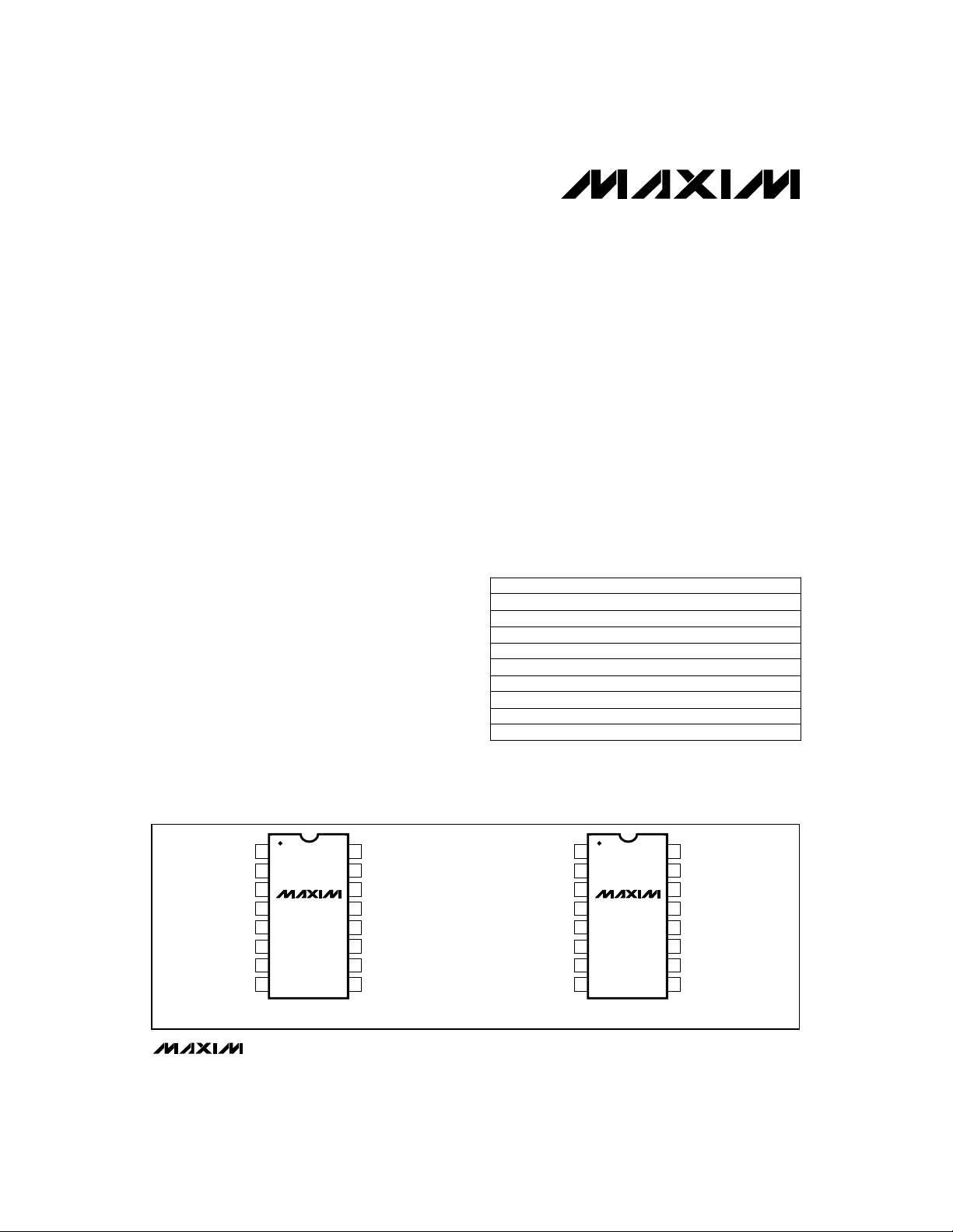
__________________________________________________________Pin Configurations
A0
1
2
EN
V-
3
IN1
IN2
IN3
IN4
OUT
Pin Configurations continued at end of data sheet.
MAX378
4
5
6
7
8
DIP
________________________________________________________________
A1
16
A2
15
GND
14
13
V+
12
IN5
11
IN6
10
IN7
9
IN8
TOP VIEW
IN1A
IN2A
IN3A
IN4A
OUTA
A0
1
2
EN
V-
3
MAX379
4
5
6
7
8
DIP
A1
16
GND
15
V+
14
13
IN1B
12
IN2B
11
IN3B
10
IN4B
9
OUTB
Maxim Integrated Products
Call toll free 1-800-998-8800 for free samples or literature.
1
Page 2
High-Voltage, Fault-Protected
Analog Multiplexers
ABSOLUTE MAXIMUM RATINGS
Voltage between Supply Pins..............................................+44V
V+ to Ground...................................................................+22V
V- to Ground......................................................................-22V
Digital Input Overvoltage:
VEN, V
Analog Input with Multiplexer Power On..............................±65V
Analog Input with Multiplexer Power Off..............................±80V
Stresses beyond those listed under “Absolute Maximum Ratings” may cause permanent damage to the device. These are stress ratings only, and functional
operation of the device at these or any other conditions beyond those indicated in the operational sections of the specifications is not implied. Exposure to
absolute maximum rating conditions for extended periods may affect device reliability.
V+......................................................................+4V
A
{
V-........................................................................-4V
Recommended V+.....................................+15V
{}
Power Supplies V-.......................................-15V
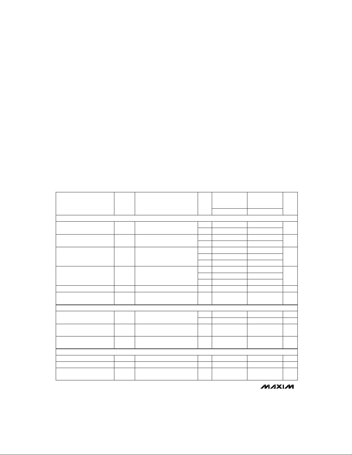
ELECTRICAL CHARACTERISTICS
(V+ = +15V, V- = -15V; VAH(Logic Level High) = +2.4V, VAL(Logic Level Low) = +0.8V, unless otherwise noted.)
MAX378/MAX379
CONDITIONS UNITS
V
= ±10V, IIN= 100µA
OUT
VAL= 0.8V, VAH= 2.4V
VIN= ±10V, V
= 0.8V (Note 6)
V
EN
V
OUT
VEN= 0.8V MAX378
(Note 6) MAX379
V
IN(ALL)
VAH= VEN= 2.4V MAX378
VAL= 0.8V (Note 5) MAX379
(Note 2)
MAX379 only
(Note 6)
V
OUT
(Notes 3, 4)
VIN= ±60V, V
(Notes 3, 4)
VIN= ±75V, VEN= V
A0= A1= A2= 0V or 5V
(Note 4)
(Note 4)
VA= 5V or 0V (Note 5)
OUT
= ±10V, VIN= 10V
= V
OUT
= 0V, VIN= ±60V
OUT
STATIC
ON Resistance
OFF Input Leakage Current
OFF Output Leakage Current
ON Channel Leakage Current
Analog Signal Range
Differential OFF Output
Leakage Current
FAULT
Output Leakage Current
(with Input Overvoltage)
Input Leakage Current
(with Overvoltage)
Input Leakage Current
(with Power Supplies Off)
CONTROL
Input Low Threshold
Input High Threshold
Input Leakage Current
(High or Low)
SYMBOLPARAMETER TEMP
r
DS(ON)
I
IN(OFF)
I
OUT(OFF)
I
OUT(ON)
AN
DIFF
I
OUT(OFF)
IN(OFF)
IN(OFF)
AL
AH
A
Continuous Current, IN or OUT...........................................20mA
Peak Current, IN or OUT
(Pulsed at 1ms, 10% duty cycle max) ............................40mA
Power Dissipation (Note 1) (CERDIP)................................1.28W
Operating Temperature Range:
MAX378/379C.....................................................0°C to +70°C
MAX378/379E..................................................-40°C to +85°C
MAX378/379M ...............................................-55°C to +125°C
Storage Temperature Range.............................-65°C to +150°C
Note 1: Derate 12.8mW/°C above TA= +75°C
0°C to +70°C
and
-40°C to +85°C
2.0 3.5
3.0 4.0
-1.0 0.03 1.0
-50 50
-2.0 0.1 2.0
-200 200
-100 100
-20 0.1 20
-600 600
-15 +15
-50 50
20
2.4
-1.0 1.0
±
= 10V
±
= ±10V
= ±10V
OUT
-55°C to +125°C
MIN TYP MAX MIN TYP MAX
+25°C
Full
+25°C
Full
+25°C
Full
Full
+25°C
Full
Full
Full
Full
+25°C
Full
+25°C
= 0V
+25°C 20
Full
Full
Full
2.0 3.0
3.0 4.0
-0.5 0.03 0.5
-50 50
-1.0 0.1 1.0
-100 100
-10 0.1 10
-300 300 -300 300
20
40
0.8
kΩ
nA
nA-200 200
nA-600 600
V-15 +15V
nA-50 50I
nA20
µA10
µA25I
µA10I
V0.8V
V2.4V
µA-1.0 1.0I
2 _______________________________________________________________________________________
Page 3
High-Voltage, Fault-Protected
Analog Multiplexers
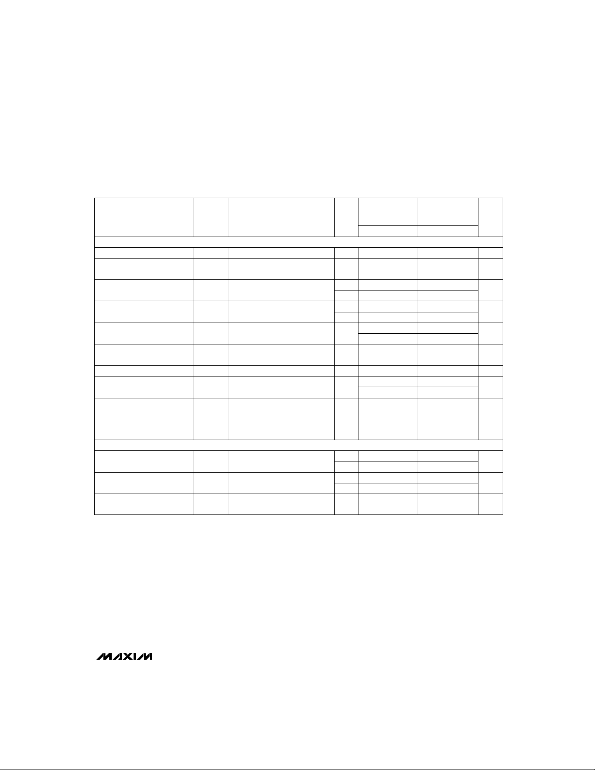
ELECTRICAL CHARACTERISTICS (continued)
(V+ = +15V, V- = -15V; VAH(Logic Level High) = +2.4V, VAL(Logic Level Low) = +0.8V, unless otherwise noted.)
1000
1000
0°C to +70°C
and
-40°C to +85°C
400 1000
1500
300
1000
1.2
3.5
50 68
5
25
12
5
0.1
0.2 1.0
0.5 1.0
0.01 0.1
0.02 0.1
±4.5 ±18
.
SYMBOLPARAMETER
DYNAMIC
Access Time +25°C 0.5 1.0
Break-Before-Make Delay
(Figure 2)
Enable Delay (ON)
Enable Delay (OFF)
Settling Time (0.1%)
(0.01%)
“OFF Isolation”
Channel Input Capacitance
Channel Output Capacitance
Digital Input Capacitance
Input to Output Capacitance
SUPPLY
Power-Supply Range for
Continuous Operation
Note 2: When the analog signal exceeds +13.5V or -12V, the blocking action of Maxim’s gate structure goes into operation. Only
leakage currents flow and the channel ON resistance rises to infinity.
Note 3: The value shown is the steady-state value. The transient leakage is typically 50µA. See
Note 4: Guaranteed by other static parameters.
Note 5: Digital input leakage is primarily due to the clamp diodes. Typical leakage is less than 1nA at +25°C.
Note 6: Leakage currents not tested at T
Note 7: Electrical characteristics, such as ON Resistance, will change when power supplies other than ±15V are used.
t
ON(EN)
t
OFF(EN)
t
SETT
IN(OFF)
C
OUT(OFF)
DS(OFF)
I+Positive Supply Current
I-Negative Supply Current
OP
A
OFF
(ISO)
A
A
= cold temp.
CONDITIONS
Figure 1 µs0.5 1.0t
VEN= +5V, VIN= ±10V
A0, A1, A2strobed
Figure 3
Figure 3
VEN= 0.8V, RL= 1kΩ, CL= 15pF
V = 7V
VEN= 0.8V or 2.4V
All VA= 0V or 5V
VEN= 0.8V or 2.4V
All VA= 0V or 5V
(Note 7)
, f = 100kHz
RMS
MAX378
MAX379
-55°C to +125°C
TEMP
MIN TYP MAX MIN TYP MAX
+25°C 25 200
+25°C
Full
+25°C
Full
+25°C
+25°C
+25°C
+25°C
+25°C
+25°C
+25°C
Full
+25°C
Full
+25°C
400 750
300 500
1.2
3.5
25
12
0.1 0.6
0.3 0.7
0.01 0.1
0.02 0.2
Detailed Description
MAX378/MAX379
UNITS
ns25 200tON-t
ns
ns
µs
dB50 68OFF
pF5C
pF
pF5C
pF0.1C
mA
mA
V±4.5 ±18V
_______________________________________________________________________________________ 3
Page 4
High-Voltage, Fault-Protected
Analog Multiplexers
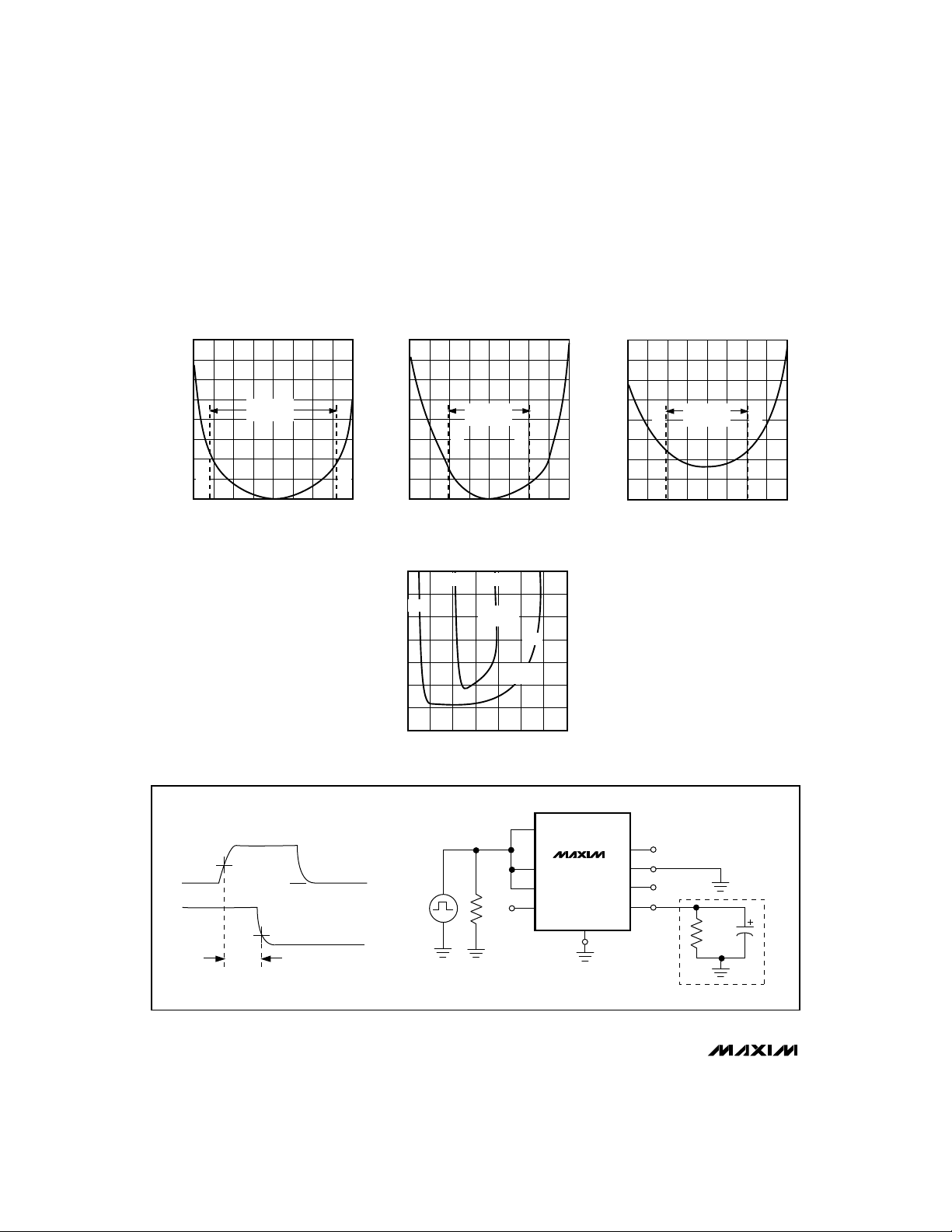
__________________________________________Typical Operating Characteristics
INPUT LEAKAGE vs.
INPUT VOLTAGE WITH V+ = V- = 0V
1m
100µ
10µ
1µ
100n
10n
INPUT CURRENT (A)
1n
100p
10p
MAX378/MAX379
-100 -50 50 100
NOTE: Typical R
Analog in (±15V supplies) = 2%
for lowest to highest R
channel; @ -10V Analog in,
-80V
OPERATING
RANGE
V
DS(ON)
IN
+80V
0
(V)
match @ +10V
DS(ON)
match = 3%.
MAX378-1
OFF CHANNEL LEAKAGE CURRENT vs.
INPUT VOLTAGE WITH ±15V SUPPLIES
100µ
10µ
1µ
100n
(A)
10n
IN(OFF)
I
1n
100p
10p
1p
-120 -60 60 120
OPERATING
RANGE
-60V
V
IN
0
(V)
DRAIN-SOURCE ON-RESISTANCE vs.
ANALOG INPUT VOLTAGE
(kΩ)
DS(ON)
R
7
6
5
4
3
2
1
0
+3.5V +4V
+13V
-10 -5 5 15-15 0 20
±5V
SUPPLIES
SUPPLIES
ANALOG INPUT (V)
±15V
OUTPUT LEAKAGE CURRENT vs. OFF CHANNEL
OVERVOLTAGE WITH ±15V SUPPLIES
10n
MAX378-2
1n
(A)
100p
OUT(OFF)
+60V
+13V
10
I
10p
1p
-120 -60 60 120
MAX3784
-60V
OPERATING
RANGE
0
V
IN(OFF)
(V)
MAX378-3
+60V
A2
MAX378
A1
A0
+V
AH
EN
GND
IN2-IN7
OUT
IN1
±10V
IN2
±
IN8
10V
+10V
50%
MAX378: VAH = 3.0V
90%
t
A
ADDRESS
DRIVE (V
OUTPUT A
-10V
)
A
0V
V
A
50Ω
Figure 1. Access Time vs. Logic Level (High)
4 _______________________________________________________________________________________
PROBE
10M
14pF
Page 5

High-Voltage, Fault-Protected
Analog Multiplexers
MAX378/MAX379
MAX358: VAH = 3.0V
ADDRESS
0V
t
OPEN
DRIVE (V
OUTPUT
50%50%
Figure 2. Break-Before-Make Delay (t
90%
t
ON(EN)
= 3.0V
AH
ON(EN)
ENABLE DRIVE
t
OFF(EN)
, t
OFF(EN)
MAX378: V
50%
Figure 3. Enable Delay (t
A
OPEN
OUTPUT
)
90%
A2
MAX378*
A1
V
A
50Ω
A0
2.4V
EN
*SIMILAR CONNECTION FOR MAX379
GND
IN2-IN7
OUT
IN1
IN2
IN8
1k
+5V
V
OUT
12.5pF
)
A2
MAX378*
0V
V
A
50Ω
A1
A0
EN
*SIMILAR CONNECTION FOR MAX379
IN1
IN2-IN7
OUT
GND
+10V
1k
12.5pF
)
+15V+5V
V-
A0
A1
A2
MAX378
EN
±60V
I
IN1
IN8
V
±10V
ANALOG
SIGNAL
-15V
OUT
V-
GND
Figure 4. Input Leakage Current (Overvoltage)
_______________________________________________________________________________________ 5
0V
V-
+5V
or
0V
10k
±75V
A0
A1
A2
MAX378
EN
I
IN1
OUT
V-
GND
0V
10k
Figure 5. Input Leakage Current (with Power Supplies OFF)
Page 6

High-Voltage, Fault-Protected
Analog Multiplexers
Truth Table—MAX378
A2 A1 A0 EN
X
0
0
0
0
1
1
1
1
MAX378/MAX379
X
0
0
1
1
0
0
1
1
THERMOCOUPLE
STRAIN GUAGE
4-20mA LOOP
TRANSMITTER
+10V
GAIN REFERENCE
ZERO REFERENCE
X
0
1
0
1
0
1
0
1
0
1
1
1
1
1
1
1
1
IN1
IN2
IN3
IN4
IN5
IN6
IN7
IN8
V- GND
-15V
MAX378
+15V
V+
ON
SWITCH
NONE
1
2
3
4
5
6
7
8
OUT
Truth Table—MAX379
A1 A0 EN
X
0
0
1
1
Note: Logic “0” = VAL≤ 0.8V, Logic “1” = VAH≥ 2.4V
+15V
V+
OUT
DG508A
MAX358
OR
MAX378
V- GND
-15V
IN1
IN2
IN3
IN4
IN5
MAX420
X
0
1
0
1
+15V
-15V
0
1
1
1
1
ON
SWITCH
NONE
1
2
3
4
1M
100k
10k
1k
111Ω
Figure 6. Typical Data Acquisition Front End
_______________Typical Applications
Figure 6 shows a typical data acquisition system
using the MAX378 multiplexer. Since the multiplexer
is driving a high-impedance input, its error is a function of its own resistance (R
plexer leakage current (I
bias current (I
V
ERR
= R
BIAS
DS(ON)
):
x (I
OUT(ON)
OUT(ON)
= 2.0kΩ x (2nA + 30pA)
= 18.0µV maximum error
In most cases, this error is low enough that preamplification of input signals is not needed, even with very
low-level signals such as 40µV/°C from type J thermocouples.
6 _______________________________________________________________________________________
) times the multi-
DS(ON)
) and the amplifier
+ I
(MAX420))
BIAS
In systems with fewer than eight inputs, an unused channel can be connected to the system ground reference
point for software zero correction. A second channel
connected to the system voltage reference allows gain
correction of the entire data acquisition system as well.
A MAX420 precision op amp is connected as a programmable-gain amplifier, with gains ranging from 1 to
10,000. The guaranteed 5µV unadjusted offset of the
MAX420 maintains high signal accuracy, while programmable gain allows the output signal level to be scaled to
the optimum range for the remainder of the data acquisition system, normally a Sample/Hold and A/D. Since
the gain-changing multiplexer is not connected to the
external sensors, it can be either a DG508A multiplexer
or the fault-protected MAX358 or MAX378.
Page 7

High-Voltage, Fault-Protected
Analog Multiplexers
Input switching, however, must be done with a faultprotected MAX378 multiplexer, to provide the level of
protection and isolation required with most data acquisition inputs. Since external signal sources may continue to supply voltage when the multiplexer and system
power are turned off, non-fault-protected multiplexers,
or even first-generation fault-protected devices, will
allow many milliamps of fault current to flow from outside sources into the multiplexer. This could result in
damage to either the sensors or the multiplexer. A nonfault-protected multiplexer will also allow input overvoltages to appear at its output, perhaps damaging
Sample/Holds or A/Ds. Such input overdrives may also
cause input-to-input shorts, allowing the high current
output of one sensor to possibly damage another.
The MAX378 eliminates all of the above problems. It
not only limits its output voltage to safe levels, with or
without power applied (V+ and V-), but also turns all
channels off when power is removed. This allows it to
draw only sub-microamp fault currents from the inputs,
and maintain isolation between inputs for continuous
input levels up to ±75V with power supplies off.
_______________Detailed Description
Fault Protection Circuitry
The MAX378/MAX379 are fully fault protected for continuous input voltages up to ±60V, whether or not the V+
and V- power supplies are present. These devices use
a “series FET” switching scheme which not only protects the multiplexer output from overvoltage, but also
limits the input current to sub-microamp levels.
Figures 7 and 8 show how the series FET circuit protects against overvoltage conditions. When power is
off, the gates of all three FETs are at ground. With a -60V
input, N-channel FET Q1 is turned on by the +60V gate-
+60V
OVERVOLTAGE
N-CHANNEL MOSFET
IS TURNED OFF
GS
= -60V
BECAUSE V
Q
1
S
D
G
Q
2
D
S
G
Q
3
D
S
G
Figure 8. +60V Overvoltage with Multiplexer Power OFF
-60V
OVERVOLTAGE
N-CHANNEL MOSFET
IS TURNED OFF
GS
= +45V
BECAUSE V
-15V +15V -15V
-60V
Q
2
+15V FROM
DRIVERS
Q
1
-15V FROM
DRIVERS
P-CHANNEL
MOSFET IS OFF
+60V FORCED
ON COMMON
OUTPUT
LINE BY
EXTERNAL
CIRCUITRY
Q
3
N-CHANNEL
MOSFET IS OFF
Figure 9. -60V Overvoltage on an OFF Channel with
Multiplexer Power Supply ON
MAX378/MAX379
-60V
OVERVOLTAGE
N-CHANNEL MOSFET
IS TURNED ON
GS
= +60V
BECAUSE V
Q
1
S
G
P-CHANNEL
MOSFET IS OFF
Q
-60V
2
D
S
D
G
Q
3
D
S
G
Figure 7. -60V Overvoltage with Multiplexer Power OFF
_______________________________________________________________________________________ 7
-15V +15V -15V
+60V
OVERVOLTAGE
N-CHANNEL MOSFET
IS TURNED ON
GS
= -45V
BECAUSE V
Q
1
V
TN = +1.5V
+15V FROM
DRIVERS
+13.5V
Q
2
-15V FROM
DRIVERS
Q
3
N-CHANNEL
MOSFET IS ON
Figure 10. +60V Overvoltage Input to the ON Channel
+13.5V
OUTPUT
Page 8

High-Voltage, Fault-Protected
Analog Multiplexers
to-source voltage. The P-channel device (Q2), however, has +60V VGSand is turned off, thereby preventing
the input signal from reaching the output. If the input
voltage is +60V, Q1 has a negative VGS, which turns it
off. Similarly, only sub-microamp leakage currents can
flow from the output back to the input, since any voltage will turn off either Q1 or Q2.
Figure 9 shows the condition of an OFF channel with
V+ and V- present. As with Figures 7 and 8, either an
N-channel or a P-channel device will be off for any
input voltage from -60V to +60V. The leakage current
with negative overvoltages will immediately drop to a
few nanoamps at +25°C. For positive overvoltages,
that fault current will initially be 40µA or 50µA, decaying
over a few seconds to the nanoamp level. The time
constant of this decay is caused by the discharge of
MAX378/MAX379
stored charge from internal nodes, and does not compromise the fault-protection scheme.
Figure 10 shows the condition of the ON channel with
V+ and V- present. With input voltages less than ±10V,
all three FETs are on and the input signal appears at the
output. If the input voltage exceeds V+ minus the Nchannel threshold voltage (VTN), then the N-channel
FET will turn off. For voltages more negative than Vminus the P-channel threshold (VTP), the P-channel
device will turn off. Since VTNis typically 1.5V and V
is typically 3V, the multiplexer’s output swing is limited
to about -12V to +13.5V with ±15V supplies.
The
Typical Operating Characteristics
graphs show typical leakage vs. input voltage curves. Although the maximum rated input of these devices is ±65V, the
MAX378/MAX379 typically have excellent performance
up to ±75V, providing additional margin for the unknown
transients that exist in the real world. In summary, the
MAX378/MAX379 provide superior protection from all
fault conditions while using a standard, readily produced junction-isolated CMOS process.
Switching Characteristics
and Charge Injection
Table 1 shows typical charge-injection levels vs.
power-supply voltages and analog input voltage. Note
that since the channels are well matched, the differential charge injection for the MAX379 is typically less
than 5pC. The charge injection that occurs during
switching creates a voltage transient whose magnitude
is inversely proportional to the capacitance on the multiplexer output.
The channel-to-channel switching time is typically 600ns,
with about 200ns of break-before-make delay. This 200ns
break-before-make delay prevents the input-to-input short
that would occur if two input channels were simultaneous-
ly connected to the output. In a typical data acquisition
system, such as in Figure 6, the dominant delay is not the
switching time of the MAX378 multiplexer, but is the settling time of the following amplifiers and S/H. Another limiting factor is the RC time constant of the multiplexer
R
plus the signal source impedance multiplied by
DS(ON)
the load capacitance on the output of the multiplexer.
Even with low signal source impedances, 100pF of capacitance on the multiplexer output will approximately double
the settling time to 0.01% accuracy.
Operation with Supply Voltage
Other than ±15V
The main effect of supply voltages other than ±15V is
the reduction in output signal range. The MAX378 limits
the output voltage to about 1.5V below V+ and about 3V
above V-. In other words, the output swing is limited to
+3.5V to -2V when operating from ±5V. The
Operating Characteristics
graphs show typical R
for ±15V, ±10V, and ±5V power supplies. Maxim tests
and guarantees the MAX378/MAX379 for operation from
±4.5V to ±18V supplies. The switching delays are
increased by about a factor of 2 at ±5V, but breakbefore-make action is preserved.
The MAX378/MAX379 can be operated with a single +9V
to +22V supply, as well as asymmetrical power supplies
TP
such as +15V and -5V. The digital threshold will remain
approximately 1.6V above GND and the analog characteristics such as R
are determined by the total voltage
DS(ON)
difference between V+ and V-. Connect V- to 0V when
operating with a +9V to +22V single supply.
This means that the MAX378/MAX379 will operate with
standard TTL-logic levels, even with ±5V power supplies. In all cases, the threshold of the EN pin is the
same as the other logic inputs.
Table 1a. MAX378 Charge Injection
Supply Voltage Analog Input Level Injected Charge
±5V
±10V
±15V
Test Conditions: CL= 1000pF on multiplexer output; the tabulated analog input level is applied to channel 1; channels 2
through 8 are open circuited. EN = +5V, A1 = A2 = 0V, A0 is
toggled at 2kHz rate between 0V and 3V. +100pC of charge
creates a +100mV step when injected into a 1000pF load
capacitance.
+1.7V
0V
-1.7V
+5V
0V
-5V
+10V
0V
-10V
+100pC
+70pC
+45pC
+200pC
+130pC
+60pC
+500pC
+180pC
+50pC
Typical
DS(ON)
,
8 _______________________________________________________________________________________
Page 9

High-Voltage, Fault-Protected
Analog Multiplexers
Table 1b. MAX379 Charge Injection
Supply
Voltage
±5V
±10V
±15V
Test Conditions: CL= 1000pF on Out A and Out B; the tabulated analog input level is applied to inputs 1A and 1B; channels
2 through 4 are open circuited. EN = +5V, A1 = 0V, A0 is toggled from 0V to 3V at a 2kHz rate.
Analog
Input Level
+1.7V
0V
-1.7V
+5V
0V
-5V
+10V
0V
-10V
The typical digital threshold of both the address lines
and the EN pin is 1.6V, with a temperature coefficient of
about -3mV/°C. This ensures compatibility with 0.8V to
2.4V TTL-logic swings over the entire temperature
range. The digital threshold is relatively independent of
the supply voltages, moving from 1.6V typical to 1.5V
typical as the power supplies are reduced from ±15V to
±5V. In all cases, the digital threshold is referenced to
GND.
The digital inputs can also be driven with CMOS-logic
levels swinging from either V+ to V- or from V+ to GND.
The digital input current is just a few nanoamps of leakage at all input voltage levels, with a guaranteed maximum of 1µA. The digital inputs are protected from ESD
by a 30V zener diode between the input and V+, and
can be driven ±4V beyond the supplies without drawing
excessive current.
Operation as a Demultiplexer
The MAX378/MAX379 will function as a demultiplexer,
where the input is applied to the OUT pin, and the input
pins are used as outputs. The MAX378/MAX379 provide both break-before-make action and full fault protection when operated as a demultiplexer, unlike earlier
generations of fault-protected multiplexers.
Channel-to-Channel Crosstalk,
Off Isolation, and Digital Feedthrough
At DC and low frequencies, channel-to-channel
crosstalk is caused by variations in output leakage cur-
Injected Charge
Out A Out B
+105pC
+73pC
+48pC
+215pC
+135pC
+62pC
+525pC
+180pC
+55pC
+107pC
+74pC
+50pC
+220pC
+139pC
+63pC
+530pC
+185pC
+55pC
Differential
A-B
-2pC
-1pC
-2pC
-5pC
-4pC
-1pC
-5pC
-5pC
0pC
Digital Interface Levels
rents as the off-channel input voltages are varied. The
MAX378 output leakage varies only a few picoamps as
all seven off inputs are toggled from -10V to +10V. The
output voltage change depends on the impedance level
at the MAX378 output, which is R
DS(ON)
plus the input
signal source resistance in most cases, since the load
driven by the MAX378 is usually a high impedance. For
a signal source impedance of 10kΩ or lower, the DC
crosstalk exceeds 120dB.
Table 2 shows typical AC crosstalk and off-isolation performance. Digital feedthrough is masked by the analog
charge injection when the output is enabled. When the
output is disabled, the digital feedthrough is virtually
unmeasurable, since the digital pins are physically isolated from the analog section by the GND and V- pins.
The ground plane formed by these lines is continued
onto the MAX378/MAX379 die to provide over 100dB
isolation between the digital and analog sections.
Table 2a. Typical Off-Isolation
Rejection Ratio
Frequency 100kHz 500kHz 1MHz
One Channel Driven
All Channels Driven
Test Conditions: VIN= 20V
= 1.5kΩ between OUT and GND, EN = 0V.
R
L
OIRR = 20 Log ____________
74dB 72dB 66dB
64dB 48dB 44dB
at the tabulated frequency,
P-P
20V
P-P
V
OUT (P-P)
Table 2b. Typical Crosstalk
Rejection Ratio
Frequency
FL= 1.5k
RL= 10k
Test Conditions: Specified RLconnected from OUT to GND,
EN = +5V, A0 = A1 = A2 = +5V (Channel 1 selected). 20V
at the tabulated frequency is applied to Channel 2. All other
channels are open circuited. Similar crosstalk rejection can be
observed between any two channels.
100kHz 500kHz 1MHz
70dB 68dB 64dB
62dB 46dB 42dB
P-P
MAX378/MAX379
_______________________________________________________________________________________ 9
Page 10

High-Voltage, Fault-Protected
Analog Multiplexers
_____________________________________________Pin Configurations (continued)
TOP VIEW
A0
1
EN
2
N.C.
3
N.C.
4
MAX378
V-
5
MAX378/MAX379
IN1
IN2
IN3
IN4
N.C.
N.C.
OUT
6
7
8
9
10
11
12
24
23
22
21
20
19
18
17
16
15
14
13
SO
A0
N.C.
A1
2
1
20
IN1
N.C.
IN2
IN3
EN
3
V-
5
6
7
8
MAX378
N.C.
N.C.
IN1A
IN2A
IN3A
IN4A
N.C.
N.C.
OUTA
A0
1
EN
2
3
4
V-
MAX379
5
6
7
8
9
10
11
12
A1
24
N.C.
23
GND
22
N.C.
21
V+
20
IN1B
19
IN2B
18
IN3B
17
IN4B
16
N.C.
15
N.C.
14
OUTB
13
A1
A2
GND
N.C.
V+
IN5
IN6
N.C.
IN7
N.C.
N.C.
IN8
SO
A0
A2
19
IN1A
N.C.
IN2A
IN3A
V-
5
6
7
8
184
GND
17
V+
16
N.C.
15
IN5
14
IN6
EN
3
2
MAX379
N.C.
1
A1
GND
20
19
184
V+
17
IN1B
16
N.C.
15
IN2B
14
IN3B
9
IN4
101112
OUT
N.C.
LCC
IN8
13
IN7
9
IN4A
101112
N.C.
OUTA
LCC
OUTB
13
IN4B
10 ______________________________________________________________________________________
Page 11

High-Voltage, Fault-Protected
Analog Multiplexers
_Ordering Information (continued)
PART
MAX379CPE
MAX379CWG
MAX379CJE 0°C to +70°C
MAX379C/D 0°C to +70°C Dice**
MAX379EPE
MAX379EWG -40°C to +85°C
MAX379EJE
MAX379MJE -55°C to +125°C
MAX379MLP -55°C to +125°C 20 LCC*
* Contact factory for availability.
**The substrate may be allowed to float or be tied to V+ (JI CMOS).
TEMP. RANGE PIN-PACKAGE
0°C to +70°C
0°C to +70°C
-40°C to +85°C 16 Plastic DIP
-40°C to +85°C 16 CERDIP
16 Plastic DIP
24 Wide SO
16 CERDIP
24 Wide SO
16 CERDIP
_________________Chip Topographies
MAX378
IN8 OUT
IN7
IN7
IN6
IN5
V+
GND
A2 A1 EN
0.151"
(3.835mm)
NOTE: Connect substrate to V+ or leave it floating.
MAX379
OUTB OUTA
IN4B
IN4
IN3
0.229"
(5.816mm)
IN2
IN1
V-
A0
IN4A
MAX378/MAX379
IN3B
IN2B
IN1B
V+
GND
A0
A1 EN
0.151"
(3.835mm)
NOTE: Connect substrate to V+ or leave it floating.
______________________________________________________________________________________ 11
IN3A
(5.816mm)
IN2A
IN1A
V-
0.229"
Page 12

High-Voltage, Fault-Protected
Analog Multiplexers
________________________________________________________Package Information
INCHES MILLIMETERS
DIM
D
A
0.101mm
e
B
A1
0.004in.
C
0°- 8°
L
A
A1
B
C
E
e
H
L
MIN
0.093
0.004
0.014
0.009
0.291
0.394
0.016
0.050
MAX
0.104
0.012
0.019
0.013
0.299
0.419
0.050
MIN
2.35
0.10
0.35
0.23
7.40
10.00
0.40
1.27
MAX
2.65
0.30
0.49
0.32
7.60
10.65
1.27
MAX378/MAX379
HE
D1
D
A2
A
L
A1
Wide SO
SMALL-OUTLINE
PACKAGE
(0.300 in.)
E
E1
A3
α
DIM
D
D
D
D
D
DIM
A
A1
A2
A3
B
B1
C
D
D1
E
E1
e
e
e
L
α
A
B
INCHES MILLIMETERS
PINS
MIN
MAX
–
0.413
0.463
0.512
0.614
0.713
MIN
10.10
11.35
12.60
15.20
17.70
MIN
–
0.38
3.18
1.40
0.41
1.27
0.20
18.92
0.13
7.62
6.10
–
2.92
0˚
0.398
16
0.447
18
0.496
20
0.598
24
0.697
28
INCHES MILLIMETERS
MAX
MIN
0.200
–
0.015
0.150
0.125
0.080
0.055
0.022
0.016
0.065
0.050
0.012
0.008
0.765
0.745
0.030
0.005
0.325
0.300
0.280
0.240
0.100 BSC
0.300 BSC
0.400
–
0.150
0.115
15˚
0˚
21-0042A
2.54 BSC
7.62 BSC
MAX
10.50
11.75
13.00
15.60
18.10
MAX
5.08
–
3.81
2.03
0.56
1.65
0.30
19.43
0.76
8.26
7.11
10.16
3.81
15˚
21-587A
16-PIN PLASTIC
e
B1
B
Maxim cannot assume responsibility for use of any circuitry other than circuitry entirely embodied in a Maxim product. No circuit patent licenses are
Maxim cannot assume responsibility for use of any circuitry other than circuitry entirely embodied in a Maxim product. No circuit patent licenses are
implied. Maxim reserves the right to change the circuitry and specifications without notice at any time.
implied. Maxim reserves the right to change the circuitry and specifications without notice at any time.
12
__________________Maxim Integrated Products, 120 San Gabriel Drive, Sunnyvale, CA 94086 (408) 737-7600
12
__________________Maxim Integrated Products, 120 San Gabriel Drive, Sunnyvale, CA 94086 (408) 737-7600
© 1994 Maxim Integrated Products Printed USA is a registered trademark of Maxim Integrated Products.
© 1994 Maxim Integrated Products Printed USA is a registered trademark of Maxim Integrated Products.
C
e
A
e
B
DUAL-IN-LINE
PACKAGE
 Loading...