

19-0380; Rev 0; 3/95
1µA Supply Current, 1.8V to 4.25V-Powered
RS-232 Transceiver with AutoShutdown™
_______________General Description
The MAX3218 RS-232 transceiver is intended for battery-powered EIA/TIA-232E and V.28/V.24 communications interfaces that need two drivers and two receivers
with minimum power consumption from a single lowvoltage supply. It provides a wide +1.8V to +4.25V
operating voltage range while maintaining true RS-232
and EIA/TIA-562 voltage levels. The MAX3218 runs
from two alkaline, NiCd, or NiMH cells without any form
of voltage regulator. A guaranteed 120kbps data rate
provides compatibility with popular software for communicating with personal computers.
Supply current is reduced to 1µA with Maxim’s new
AutoShutdown™ feature. When the MAX3218 does not
sense a valid signal level on the receiver inputs, the onboard power-supply and drivers shut down. This
occurs if the RS-232 cable is disconnected or if the
transmitters of the connected peripheral are turned off.
The system turns on again when a valid level is applied
to either RS-232 receiver input. As a result, the system
saves power without changes to the existing software.
Additionally, the MAX3218 can be forced into or out of
shutdown, under logic control.
While shut down, all receivers can remain active or can
be disabled under logic control, permitting a system
incorporating the CMOS MAX3218 to monitor external
devices while in low-power shutdown. Three-state drivers are provided on both receiver outputs so that multiple receivers, generally of different interface standards,
can be on the same bus. The MAX3218 is available in
20-pin DIP and SSOP packages.
____________________________Features
BETTER THAN BIPOLAR!
♦ 1µA Supply Current Using AutoShutdown™
♦ Operates Directly from Two Alkaline,
NiCd or NiMH Cells
♦ +1.8V to +4.25V Single-Supply Voltage Range
♦ 120kbps Data Rate Guaranteed
♦ Low-Cost Surface-Mount Components
♦ Meets EIA/TIA-232E Specifications
♦ Three-State Receiver Outputs
♦ Flow-Through Pinout
♦ On-Board DC-DC Converters
♦ 20-Pin SSOP and DIP Packages
______________Ordering Information
PART
MAX3218CPP
MAX3218CAP 0°C to +70°C
MAX3218C/D
MAX3218EPP -40°C to +85°C
MAX3218EAP -40°C to +85°C 20 SSOP
†
Contact factory for dice specifications.
TEMP. RANGE PIN-PACKAGE
0°C to +70°C
0°C to +70°C Dice
20 Plastic DIP
20 SSOP
†
20 Plastic DIP
MAX3218*
________________________Applications
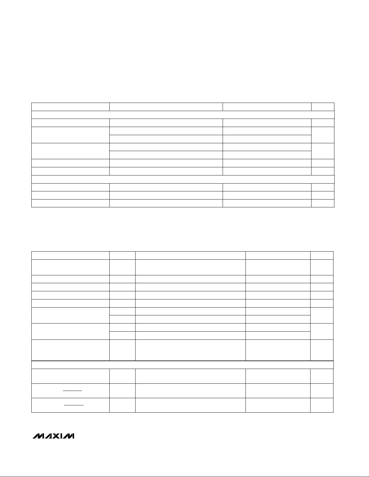
__________________Pin Configuration
Battery-Powered Equipment
Subnotebook Computers
PDAs
Hand-Held Equipment
Peripherals
Cellular Phones
* Patent Pending
™ AutoShutdown is a trademark of Maxim Integrated Products.
________________________________________________________________
TOP VIEW
INVALID
FORCEON
FORCEOFF
GND
V
T1IN
T2IN
R1OUT
R2OUT
LX
1
2
3
4
MAX3218
5
6
CC
7
8
9
10
DIP/SSOP
Call toll free 1-800-998-8800 for free samples or literature.
GND
20
V+
19
C1+
18
GND
17
C1-
16
V-
15
T1OUT
14
T2OUT
13
R1IN
12
R2IN
11
Maxim Integrated Products
1
1µA Supply Current, 1.8V to 4.25V-Powered
RS-232 Transceiver with AutoShutdown™
ABSOLUTE MAXIMUM RATINGS
Supply Voltages
....................................................................-0.3V to +4.6V
V
CC
V+.......................................................... (V
V-.......................................................................+0.3V to -7.4V
to V-..........................................................................+12V
V
CC
LX ................................................................-0.3V to (1V + V+)
Input Voltages
T_IN, FORCEON, FORCEOFF
R_IN.................................................................................±25V
MAX3218
Output Voltages
T_OUT.............................................................................±15V)
R_OUT....................................................-0.3V to (V
Stresses beyond those listed under “Absolute Maximum Ratings” may cause permanent damage to the device. These are stress ratings only, and functional
operation of the device at these or any other conditions beyond those indicated in the operational sections of the specifications is not implied. Exposure to
absolute maximum rating conditions for extended periods may affect device reliability.
............................ -0.3V to +7V
- 0.3V) to +7.5V
CC
CC
+ 0.3V)
ELECTRICAL CHARACTERISTICS
(Circuit of Figure 1, VCC= 1.8V to 4.25V, C1 = 0.47µF, C2 = C3 = C4 = 1µF, L1 = 15µH, TA= T
Typical values are at V
DC CHARACTERISTICS
Supply Current, Shutdown µA
Supply Current,
AutoShutdown™ Disabled
LOGIC INPUTS AND RECEIVER OUTPUTS
Input Logic Threshold Low
Input Logic Threshold High
AUTOSHUTDOWN (FORCEON = GND, FORCEOFF = VCC)
Receiver Input Thresholds,
Transmitters Enabled
Receiver Input Thresholds
Transmitters Disabled
INVALID Output Low Voltage 0.4
INVALID Output High Voltage V
= 3.0V, TA= +25°C.)
CC
VCC= 3.0V, TA= +25°C, all R_IN open,
FORCEON = GND, FORCEOFF = V
FORCEOFF = GND, TA= +25°C, VCC= 3.0V
FORCEON = FORCEOFF = VCC= 3.0V, no load mA2.0 3.0
T_IN, FORCEON, FORCEOFF
T_IN, FORCEON, FORCEOFF
T_IN, FORCEON = FORCEOFF = 0V or V
R_OUT, I
R_OUT, I
R_OUT, 0V ≤ R_OUT ≤ VCC,
FORCEON = FORCEOFF = 0V
Figure 4a
1µA supply current, Figure 4a
I
OUT
I
OUT
CONDITIONS
= 1.0mA
OUT
= -0.4mA
OUT
Positive threshold
Negative threshold -2.8
= 1.0mA, -0.3V < R_IN < 0.3V
= -0.4mA, |R_IN|> 2.8V
Short-Circuit Duration, R_OUT, T_OUT to GND ....... Continuous
Continuous Power Dissipation (T
Plastic DIP (derate 11.11mW/°C above +70°C) ..........889mW
SSOP (derate 8.00mW/°C above +70°C) ..................640mW
Operating Temperature Ranges
MAX3218C_ P................................................... 0°C to +70°C
MAX3218E_ P................................................. -40°C to +85°C
Storage Temperature Range ........................... -65°C to +150°C
Lead Temperature (soldering, 10sec) ........................... +300°C
CC
CC
CC
VCC- 0.25
MIN
A
to T
= +70°C)
, unless otherwise noted.
MAX
1.0 10
CC
2.8
UNITSMIN TYP MAXPARAMETER
V1.8 4.25Operating Voltage Range
µA1.0 10Supply Current, AutoShutdown™
V0.33 x V
V0.67 x V
µA0.001 ±1Input Leakage Current
V0.4Output Voltage Low
VVCC- 0.25 VCC- 0.08Output Voltage High
µA0.05 ±10Output Leakage Current
V
V-0.3 0.3
V
2 _______________________________________________________________________________________
1µA Supply Current, 1.8V to 4.25V-Powered
RS-232 Transceiver with AutoShutdown™
ELECTRICAL CHARACTERISTICS (continued)
(Circuit of Figure 1, VCC= 1.8V to 4.25V, C1 = 0.47µF, C2 = C3 = C4 = 1µF, L1 = 15µH, TA= T
Typical values are at V
EIA/TIA-232E RECEIVER INPUTS
Input Threshold Low
Input Threshold High
Input Hysteresis V
Input Resistance
EIA/TIA-232E TRANSMITTER OUTPUTS
Output Short-Circuit Current mA
= 3.0V, TA= +25°C.)
CC
VCC= 2.0V to 4.25V
VCC= 1.8V to 4.25V
VCC= 1.8V to 4.25V
V
CC
-15V < R_IN < 15V kΩ357
All transmitter outputs loaded with 3kΩ to groundOutput Voltage Swing V±5 ±6
VCC= 0V, -2V < T_OUT < 2V
CONDITIONS
0.4
0.3
= 1.8V to 3.6V
to T
MIN
MAX
0.7
±24 ±100
, unless otherwise noted.
UNITSMIN TYP MAXPARAMETER
3.0
2.8
TIMING CHARACTERISTICS
(Circuit of Figure 1, VCC= 1.8V to 4.25V, C1 = 0.47µF, C2 = C3 = C4 = 1µF, L1 = 15µH, TA= T
Typical values are at V
= 3.0V, TA= +25°C.)
CC
MIN
to T
, unless otherwise noted.
MAX
MAX3218
V-25 +25Input Voltage Range
V
V
Ω300Output Resistance
Receiver Output Enable Time
Receiver Output Disable Time
Transmitter Output Enable Time
Transmitter Output Disable Time
Receiver Propagation Delay
Transmitter Propagation Delay
AUTOSHUTDOWN TIMING
Receiver Threshold to
Transmitters Enabled
Receiver Positive or Negative
Threshold to INVALID High
Receiver Positive or Negative
Threshold to INVALID Low
ER
DR
ET
DT
PHLR
PLHR
PHLT
PLHT
WU
INVH
INVL
CONDITIONS
2500pF || 3kΩ load each transmitter, one transmitter switching, 150pF load each receiver
150pF load
150pF load
2500pF || 3kΩ load
2500pF || 3kΩ load
TA= +25°C, VCC= 3.0V, RL= 3kΩ to 7kΩ,
CL= 50pF to 2500pF, measured from
+3V to -3V or -3V to +3V
Figure 4b µs250t
Figure 4b µs1t
Figure 4b µs30t
UNITSMIN TYP MAXSYMBOLPARAMETER
kbps120 235Data Rate
ns90 300t
ns200 500t
µs250 450t
ns500t
290 1000t
260 1000t
1.9 2.7t
1.8 2.7t
ns
µs
V/µs3.0 30Transition Region Slew Rate
_______________________________________________________________________________________ 3
1µA Supply Current, 1.8V to 4.25V-Powered
RS-232 Transceiver with AutoShutdown™
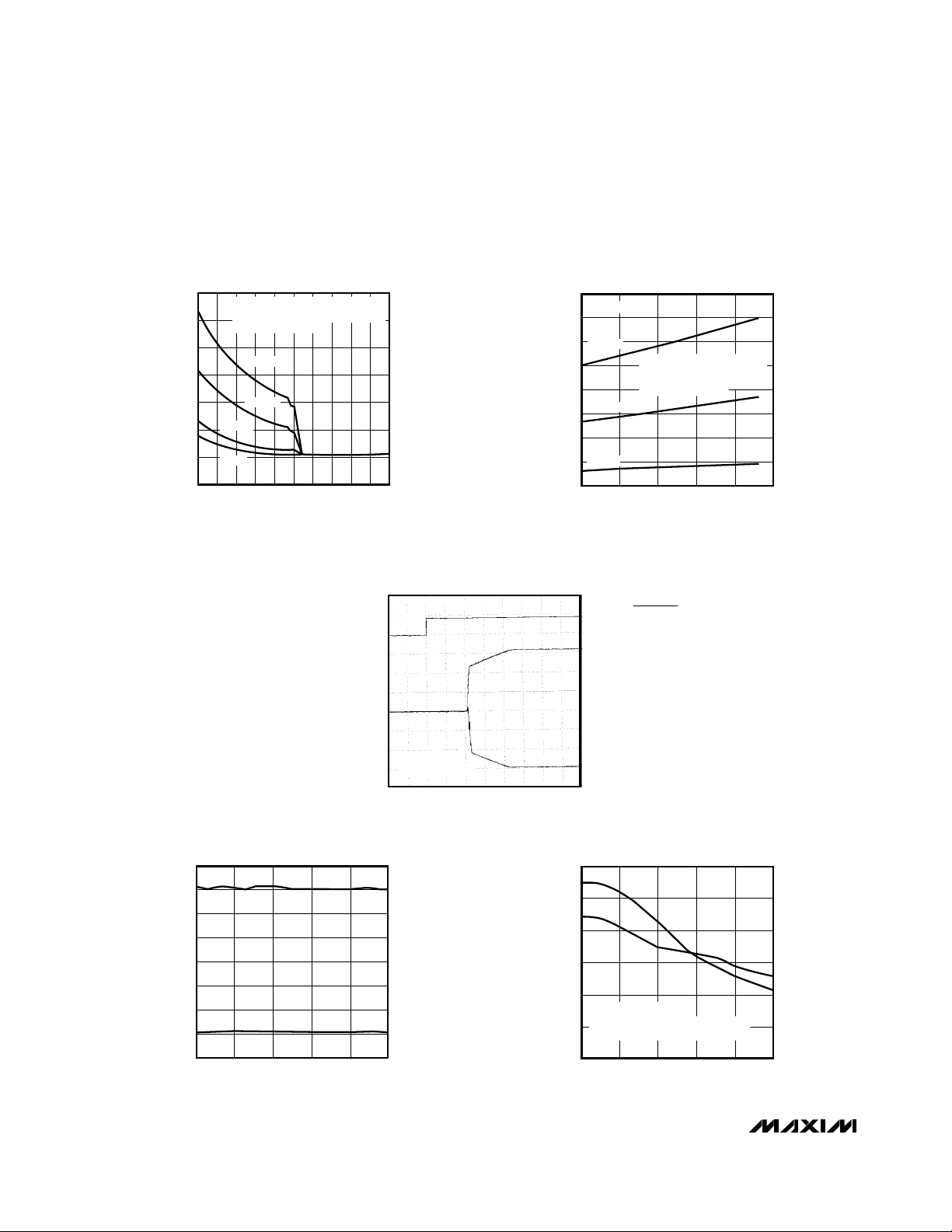
__________________________________________Typical Operating Characteristics
(Circuit of Figure 1, VCC= 1.8V, all transmitter outputs loaded with 3kΩ, TA = +25°C, unless otherwise noted.)
140
120
MAX3218
100
80
60
40
SUPPLY CURRENT (mA)
20
0
SUPPLY CURRENT vs.
SUPPLY VOLTAGE
1 TRANSMITTER FULL DATA RATE
1 TRANSMITTER 1/8 DATA RATE
RL = 3kΩ + 2500pF
240kbps
120kbps
20kbps
0kbps
2.4 3.0
1.8
SUPPLY VOLTAGE (V)
3.6
4.2
2V/div
MAX3218-01
TIME TO EXIT SHUTDOWN
(ONE TRANSMITTER HIGH,
ONE TRANSMITTER LOW)
TRANSMITTING SUPPLY CURRENT
vs. LOAD CAPACITANCE
100
VCC = 2.4V
90
80
235kbps
70
60
120kbps
50
SUPPLY CURRENT (mA)
40
20kbps
30
20
1000
0
LOAD CAPACITANCE (pF)
FORCEON, FORCEOFF
V
OH
T_OUT
TRANSMITTER 1 OPERATING
AT SPECIFIED BIT RATE,
TRANSMITTER 2 OPERATING
AT 1/16 THAT RATE.
3000
2000
4000
MAX3218-02
5000
V
1.8V
TRANSMITTER OUTPUT VOLTAGE vs.
LOAD CAPACITANCE AT 120kbps
8
6
4
2
0
-2
-4
TRANSMITTER OUTPUT VOLTAGE (V)
-6
-8
1000
0
LOAD CAPACITANCE (pF)
2000
3000
V
V
OUT+
OUT-
4000
R
MAX3218-04
5000
CC =
= 3kΩ || 2500pF
L
100µs/div
V
OL
SLEW RATE vs.
TRANSMITTER CAPACITANCE
12
10
8
6
4
SLEW RATE (V/µs)
DATA RATE 120kbps,
TRANSMITTERS LOADED WITH
2
3kΩ PLUS INDICATED CAPACITANCE
0
1000
0
+SLEW
-SLEW
2000
3000
LOAD CAPACITANCE (pF)
4 _______________________________________________________________________________________
4000
MAX3218-05
5000

1µA Supply Current, 1.8V to 4.25V-Powered
RS-232 Transceiver with AutoShutdown™
______________________________________________________________Pin Description
PIN
1
6
Inductor/Diode Connection PointLX
INVALID2
FORCEOFF4
CC
Output of Invalid Signal Detector. Low if invalid RS-232 levels are present on all receiver inputs,
otherwise high.
Drive high when FORCEOFF = high to override automatic circuitry, keeping transmitters on.FORCEON3
Drive low to shut down transmitters and on-board power supply, overriding all automatic
circuitry and FORCEON.
GroundGND5, 17, 20
Supply Voltage Input, 1.8V to 4.25V. Bypass to GND with at least 1µF.V
Transmitter InputsT1IN, T2IN7, 8
Receiver OutputsR1OUT, R2OUT9, 10
Receiver InputsR2IN, R1IN11, 12
Transmitter Outputs, swing between V+ and V-T2OUT, T1OUT13, 14
Negative Supply generated on-boardV-15
Terminal for Charge-Pump CapacitorC1-, C1+16, 18
Positive Supply generated on-boardV+19
FUNCTIONNAME
MAX3218
_______________Detailed Description
The MAX3218 line driver/receiver is intended for battery-powered EIA/TIA-232 and V.28/V.24 communications interfaces that require two drivers and two
receivers. The operating voltage extends from 1.8V to
4.25V, yet the device maintains true RS-232 and
EIA/TIA-562 transmitter output voltage levels. This wide
supply voltage range permits direct operation from a
variety of batteries without the need for a voltage regulator. For example, the MAX3218 can be run directly
from a single lithium cell or a pair of alkaline cells. It
can also be run directly from two NiCd or NiMH cells
from full-charge voltage down to the normal 0.9V/cell
end-of-life point. The 4.25V maximum supply voltage
allows the two rechargeable cells to be trickle- or fastcharged while driving the MAX3218.
The circuit comprises three sections: power supply,
transmitters, and receivers. The power-supply section
converts the supplied input voltage to 6.5V, providing the
voltages necessary for the drivers to meet true RS-232
levels. External components are small and inexpensive.
The transmitters and receivers are guaranteed to operate at 120kbps data rates, providing compatibility with
LapLink™ and other high-speed communications software.
The MAX3218 is equipped with Maxim’s new proprietary AutoShutdown™ circuitry. This achieves a 1µA
supply current by shutting down the device when the
RS-232 cable is disconnected or when the connected
peripheral transmitters are turned off. While shut down,
both receivers can remain active or can be disabled
under logic control. With this feature, the MAX3218 can
be in low-power shutdown mode and still monitor activity on external devices. Three-state drivers are provided on both receiver outputs.
Three-state drivers on both receiver outputs are provided so that multiple receivers, generally of different interface standards, can be wire-ORed at the UART.
Switch-Mode Power Supply
The switch-mode power supply uses a single inductor
with one diode and three small capacitors to generate
±6.5V from an input voltage in the 1.8V to 4.25V range.
Inductor Selection
Use a 15µH inductor with a saturation current rating of at
least 350mA and less than 1Ω resistance. Table 1 lists
suppliers of inductors that meet the 15µH/350mA/1Ω
specifications.
™ LapLink is a trademark of Traveling Software, Inc.
AutoShutdown is a trademark of Maxim Integrated Products.
_______________________________________________________________________________________ 5

1µA Supply Current, 1.8V to 4.25V-Powered
RS-232 Transceiver with AutoShutdown™
Table 1. Suggested Component Suppliers
MANUFACTURER PHONEPART NUMBER FAX
Inductors
USA (814) 237-1431LQH4N150K-TAMurata-Erie USA (814) 238-0490
MAX3218
Diodes—Surface-Mount
Diodes—Through-Hole
Motorola
CD43150Sumida
NLC453232T-150KTDK
1N5817 (Schottky)
USA (708) 956-0666
Japan (03) 3607-5111
USA (708) 803-6100
Japan (03) 3278-5111
USA (508) 853-5000TMPD6050LTAllegro USA (508) 853-7556
USA (516) 435-1110CMPSH-3 (Schottky)Central Semiconductor USA (516) 435-1824
USA (408) 749-0510MMBD6050LT1 (silicon)Motorola USA (408) 991-7420
USA (401) 762-3800PMBD6050 (silicon)Philips USA (401) 767-4493
USA (408) 749-05101N6050 (silicon),
USA (708) 956-0702
Japan (03) 3607-5428
USA (708) 803-6296
Japan (03) 3278-5358
USA (408) 991-7420
Diode Selection
Key diode specifications are fast recovery time (<10ns),
average current rating (>100mA), and peak current rating (>350mA). Inexpensive fast silicon diodes, such as
the 1N6050, are generally recommended. More expensive Schottky diodes improve efficiency and give slightly
better performance at very low VCCvoltages. Table 1
lists suppliers of both surface-mount and through-hole
diodes. 1N914s are usually satisfactory, but specifications and performance vary widely with different manufacturers.
Capacitor Selection
Use capacitors with values at least as indicated in
Figure 1. Capacitor C2 determines the ripple on V+, but
not the absolute voltage. Capacitors C1 and C3 determine both the ripple and the absolute voltage of V-.
Bypass VCCto GND with at least 1µF (C4) placed close
to pins 5 and 6. If the VCCline is not bypassed elsewhere (e.g., at the power supply), increase C4 to 4.7µF.
You may use ceramic or polarized capacitors in all
locations. If you use polarized capacitors, tantalum
types are preferred because of the high operating frequency of the power supplies (about 250kHz). If aluminum electrolytics are used, higher capacitance
values may be required.
1.8V to
4.25V
1µF
15µH 1N6050
C4
61
V
CC
3
FORCEON
4
FORCEOFF
2
INVALID
T1IN 14
7
8
T2IN
R1OUT
9
R2OUT
10
LX
MAX3218
T1
T2
R1
5k
R2
5k
GND
5, 17, 20
19
V+
V-
C1+
C1-
T1OUT
T2OUT
R1IN
R2IN
C2
1µF
15
C3
1µF
18
C1
0.47µF
16
13
12
11
Figure 1. Typical Operating Circuit
6 _______________________________________________________________________________________

1µA Supply Current, 1.8V to 4.25V-Powered
RS-232 Transceiver with AutoShutdown™
FORCEOFF
POWER
MANAGEMENT
UNIT OR
KEYBOARD
CONTROLLER
CPU
Figure 2. Interface Under Control of PMU
FORCEON
INVALID
I/O
CHIP
WITH
UART
MAX3218
RS-232
RS-232 Drivers
The two drivers are identical, and deliver EIA/TIA-232E
and EIA/TIA-562 output voltage levels when VCCis
between 1.8V and 4.25V. One transmitter can drive up
to 3kΩ in parallel with 2500pF at up to 120kbps.
Connect unused drivers to either GND or VCC. When
FORCEOFF is driven low, or when AutoShutdown circuitry senses invalid voltage levels at all receiver inputs, the
drivers are disabled and their outputs are forced into a
high-impedance state. Driver inputs do not have internal
pull-up resistors.
RS-232 Receivers
The two receivers are identical, and accept both
EIA/TIA-232E and EIA/TIA-562 input signals. The
CMOS receiver outputs are inverting and swing rail-torail. Receivers are disabled only when FORCEON and
FORCEOFF inputs are low. (See Table 2.)
Table 2. Receiver Status
FORCEON FORCEOFF RECEIVER STATUS
HX
XH
LL
When FORCEOFF is low, power supplies are disabled
and the transmitters are placed in a high-impedance
state. Receiver operation is not affected by taking
FORCEOFF low. Power consumption is dramatically
reduced in shutdown mode. Supply current is minimized
when the receiver inputs are static in any one of three
states: floating (ground), GND, or VCC.
A 1µA supply current is achieved with Maxim’s new
AutoShutdown feature, which operates when FORCEON
is low and FORCEOFF is high. When the MAX3218
senses no valid signal level on either receiver input for
typically 30µs, the on-board power supply and drivers
shut down, reducing supply current to 1µA. Internal 5kΩ
resistors pull undriven receiver inputs to ground. This
occurs if the RS-232 cable is disconnected or if the connected peripheral transmitters are turned off. The system turns on again when a valid level is applied to either
RS-232 receiver input. As a result, the system saves
power without changes to the existing BIOS or operating
system. When using the AutoShutdown feature, INVALID
is high when the device is on and low when the device is
shut down. The INVALID output indicates the condition
of the receiver inputs.
Table 3 summarizes the MAX3218 operating modes.
FORCEON and FORCEOFF override the automatic circuitry and force the transceiver into its normal operating
state or into its low-power standby state. When neither
control is asserted, the IC selects between these states
automatically based on receiver input levels. Figure 4
depicts valid and invalid RS-232 receiver levels. The
Receiver Enabled
Receiver Disabled
Shutdown
AutoShutdown™
MAX3218
Table 3. AutoShutdown Logic
RS-232 SIGNAL
PRESENT AT
RECEIVER INPUT
_______________________________________________________________________________________ 7
INVALID OUTPUTFORCEOFF INPUT TRANSCEIVER STATUSFORCEON INPUT
X
H
L
X
X
HHYes Normal Operation
LHNo Normal Operation (Forced On)
LHNo Shutdown (AutoShutdown)
HLYes Shutdown (Forced Off)
LLNo Shutdown (Forced Off)

1µA Supply Current, 1.8V to 4.25V-Powered
RS-232 Transceiver with AutoShutdown™
MAX3218 shuts down after sensing invalid RS-232 levels
for greater than 30µs, ensuring that the AutoShutdown
mode is not enabled for slow-moving signals (>1V/µs).
Another system with AutoShutdown may need a period
of time to wake up. Figure 5 shows a circuit that forces
the transmitters on for 100ms after start-up, allowing
enough time for the other system to realize that the
MAX3218 system is awake. If the other system outputs
valid RS-232 signals within that time, the RS-232 ports on
MAX3218
both systems remain enabled.
__________Applications Information
Operation from Regulated/Unregulated
Dual System Power Supplies
The MAX3218 is intended for use with three different
power-supply sources: it can be powered directly from
a battery, from a 3.0V or 3.3V power supply, or simultaneously from both. Figure 1 shows the single-supply
configuration. Figure 6 shows the circuit for operation
from both a 3V supply and a raw battery supply—an
ideal configuration where a regulated 3V supply is
being derived from two cells. In this application, the
MAX3218’s logic levels remain appropriate for interface
with 3V logic, yet most of the power for the MAX3218 is
drawn directly from the battery, without suffering the
efficiency losses of the DC-DC converter. This prolongs battery life.
Bypass the input supplies with 0.1µF at V
(C4) and at
CC
least 1µF at the inductor (C5). Increase C5 to 4.7µF if
the power supply has no other bypass capacitor connected to it.
Low-Power Operation
The following suggestions will help you get maximum
life out of your batteries.
Transmit at the highest practical data rate. Although
this raises the supply current while transmission is in
progress, the transmission will be over sooner. If the
MAX3218 is shut down (using FORCEOFF) as soon as
each transmission ends, this practice will save energy.
Operate your whole system from the raw battery voltage rather than suffer the losses of a regulator or DCDC converter. If this is not possible, but your system is
powered from two cells and employs a 3V DC-DC converter to generate the main logic supply, use the circuit
of Figure 6. This circuit draws most of the MAX3218’s
power straight from the battery, but still provides logiclevel compatibility with the 3V logic.
+0.3V to +2.8V
-0.3V to -2.8V
+
-
+
-
RxR_IN
R_OUT
FORCEOFF
FORCEON
•
FORCEON
FORCEOFF
•
•
•
•
30µs
DELAY
INVALID
•
FORCEOFF
INVALID IS AN INTERNALLY GENERATED SIGNAL
THAT IS USED BY THE AUTOSHUTDOWN LOGIC
AND APPEARS AS AN OUTPUT OF THE DEVICE.
POWER DOWN IS ONLY AN INTERNAL SIGNAL.
IT CONTROLS THE OPERATIONAL STATUS OF
THE TRANSMITTERS AND THE POWER SUPPLIES.
Figure 3. AutoShutdown Logic
8 _______________________________________________________________________________________
FORCEON
0
0
0
0
1
1
1
1
INVALID
0
0
1
1
0
0
1
1
0
1
0
1
0
1
0
1
POWER DOWN
POWER DOWN
0
0
0
0
0
1
1
1

1µA Supply Current, 1.8V to 4.25V-Powered
RS-232 Transceiver with AutoShutdown™
TRANSMITTERS ENABLED, INVALID HIGH
+2.8V
INDETERMINATE
+0.3V
-0.3V
-2.8V
AUTOSHUTDOWN RECEIVER INPUT THRESHOLD (V)
(a)
RECEIVER
INPUT
VOLTAGE
(V)
AUTOSHUTDOWN, TRANSMITTERS DISABLED,
0V
1µA SUPPLY CURRENT, INVALID LOW
INDETERMINATE
TRANSMITTERS ENABLED, INVALID HIGH
INVALID
REGION
Keep communications cables short to minimize capacitive loading. Lowering the capacitive loading on the
transmitter outputs reduces the MAX3218’s power consumption. Using short, low-capacitance cable also
helps transmission at the highest data rates.
EIA/TIA-232E and
_____________EIA/TIA-562 Standards
RS-232 circuits consume much of their power because
the EIA/TIA-232E standard demands that the transmitters deliver at least 5V to receivers with impedances
that can be as low as 3kΩ. For applications where
power consumption is critical, the EIA/TIA-562 standard
provides an alternative.
EIA/TIA-562 transmitter output voltage levels need only
reach ±3.7V, and because they have to drive the same
3kΩ receiver loads, the total power consumption is considerably reduced. Since the EIA/TIA-232E and
EIA/TIA-562 receiver input voltage thresholds are the
same, interoperability between EIA/TIA-232E and
EIA/TIA-562 devices is guaranteed. Maxim’s MAX560
and MAX561 are EIA/TIA-562 transceivers that operate
on a single supply from 3.0V to 3.6V, and the MAX562
transceiver operates from 2.7V to 5.25V while producing EIA/TIA-562 levels.
MAX3218
V
CC
INVALID
OUTPUT
(V)
(b)
0
V+
V
CC
0V
V-
t
INVL
Figure 4. AutoShutdown Trip Levels
_______________________________________________________________________________________ 9
POWER
MANAGEMENT
UNIT
t
INVH
t
WU
MASTER SHDN LINE
FORCEOFF
0.1µF 1M
FORCEON
MAX3218
Figure 5. AutoShutdown with Initial Turn-On to Wake Up a
System

1µA Supply Current, 1.8V to 4.25V-Powered
RS-232 Transceiver with AutoShutdown™
MAX3218
3V
DC-DC
CONVERTER
MAX878
OR
MAX756
OR
MAX856
15µH
C5
1µF
6
V
C4
0.1µF
CC
3
FORCEON
4
FORCEOFF
2
INVALID
T1IN 14
7
8
T2IN
9
R1OUT
R2OUT
10
1N6050
1
LX
MAX3218
T1
T2
GND
R1
R2
5, 17, 20
1µF
C2
19
V+
T1OUT
T2OUT
5k
5k
C1+
C1-
R1IN
R2IN
15
V-
18
16
13
12
11
C3
1µF
C1
0.47µF
Figure 6. Operating from Unregulated and Regulated Supplies
10 ______________________________________________________________________________________

1µA Supply Current, 1.8V to 4.25V-Powered
RS-232 Transceiver with AutoShutdown™
_____+3V-Powered EIA/TIA-232 and EIA/TIA-562 Transceivers from Maxim
GUAR-
ANTEED
DATA
RATE
(kbps)
12053/52.7 to 3.6MAX3212
12022/21.8 to 4.25MAX218
12022/21.8 to 4.25MAX3218
EIA/TIA-
232
OR 562
232
232
232
232
562
562120
FEATURES
Drives mice12053/53.0 to 3.6MAX212
AutoShutdown, complementary
receiver, drives mice, transient
detection
Operates directly from a battery
without a voltage regulator
Same as MAX218 but with
AutoShutdown
Pin-compatible with MAX214
Wide supply range56223053/52.7 to 5.25MAX562
0.1µF capacitors56212022/23.0 to 3.6MAX563
0.1µF capacitors23212022/23.0 to 5.5MAX3222
AutoShutdown, 0.1µF capacitors23212022/23.0 to 5.5MAX3223
PART
MAX560
SUPPLY
VOLTAGE
(V)
3.0 to 3.6 Pin-compatible with MAX21312024/5
No. OF
TRANSMITTERS/
RECEIVERS
No. OF
RECEIVERS
ACTIVE IN
SHUTDOWN
4/53.0 to 3.6MAX561
0
MAX3218
12022/23.0 to 5.5MAX3232
23212053/53.0 to 5.5MAX3241
23212013/53.0 to 5.5MAX3243
Pin-compatible with MAX232232
0.1µF capacitors, 2 complementary receivers, drives mice
0.1µF capacitors, AutoShutdown,
complementary receiver,
drives mice
______________________________________________________________________________________ 11

1µA Supply Current, 1.8V to 4.25V-Powered
RS-232 Transceiver with AutoShutdown™
___________________Chip Topography
INVALID
FORCEON
FORCEOFF
MAX3218
GND
V
CC
T1IN
T2IN
LX
R1OUT
(3.099mm)
GND
R2OUT
0.122"
R2IN
R1IN
V+
C1+
GND
C1V-
0.101"
(2.565mm)
T1OUT
T2OUT
TRANSISTOR COUNT: 571
SUBSTRATE CONNECTED TO GND
________________________________________________________Package Information
DIM
A
A1
B
C
α
HE
C
L
D
E
e
H
L
α
INCHES
MIN
0.068
0.002
0.010
0.004
0.205
0.301
0.025
MAX
0.078
0.008
0.015
0.008
SEE VARIATIONS
0.209
0.311
0.037
0˚
8˚
MILLIMETERS
MIN
1.73
0.05
0.25
0.09
5.20
0.65 BSC0.0256 BSC
7.65
0.63
0˚
MAX
1.99
0.21
0.38
0.20
5.38
7.90
0.95
8˚
14
16
20
24
28
INCHES
MIN
0.239
0.239
0.278
0.317
0.397
DIM
PINS
e
SSOP
A
SHRINK
SMALL OUTLINE
B
A1
PACKAGE
D
D
D
D
D
MAX
0.249
0.249
0.289
0.328
0.407
MILLIMETERS
MAX
MIN
6.33
6.07
6.33
6.07
7.33
7.07
8.33
8.07
10.33
10.07
21-0056A
D
Maxim cannot assume responsibility for use of any circuitry other than circuitry entirely embodied in a Maxim product. No circuit patent licenses are
implied. Maxim reserves the right to change the circuitry and specifications without notice at any time.
12
__________________Maxim Integrated Products, 120 San Gabriel Drive, Sunnyvale, CA 94086 (408) 737-7600
© 1995 Maxim Integrated Products Printed USA is a registered trademark of Maxim Integrated Products.
 Loading...