

Page 1
General Description
The MAX3209E is a complete, dual DTE RS-232 serial
port (6 transmitters, 10 receivers) for motherboards and
desktop PCs that ensures compliance with the stringent
ESD requirements of the European Community. The
device minimizes board space and power consumption
by eliminating the need for a negative power supply; it
integrates two serial ports and a charge pump into a single 38-pin TSSOP package.
The MAX3209E features a 50µA low-power standby
mode for compliance with system power-management
requirements. During standby, while the device operates from the single +3V to +5.5V logic supply, one
receiver on each port remains active, allowing automatic
system wake-up when peripheral communications
resume.
All transmitter outputs and receiver inputs are protected
to ±15kV using IEC 1000-4-2 Air-Gap Discharge, ±8kV
using IEC 1000-4-2 Contact Discharge, and ±15kV
using the Human Body Model, making the device ideal
for use in harsh environments or mission-critical equipment. In addition, the MAX3209E withstands ±4kV per
IEC 1000-4-4 Electrical Fast Transient/Burst Stressing.
As a result of its robust charge-pump structure, the
MAX3209E guarantees mouse driveability and true RS232 operation at data rates up to 460kbps, ensuring
compatibility with PC-to-PC communication software
(such as LapLink™).
________________________Applications
Desktop PCs
Motherboards
Instruments
Equipment Requiring IEC 1000-4-2 Compliance
Telecommunications
Network Servers
Features
♦ Two Complete Serial Ports in a Single 38-Pin
TSSOP Package
♦ Requires Only +12V Supply and Logic
Supply (+3V to +5.5V)
♦ No Negative Supply Required
♦ One Receiver Active per Port in Standby
for System Wake-Up
♦ 460kbps Data Rate; LapLink Compatible
♦ Enhanced ESD Protection
±15kV—Human Body Model
±8kV—IEC 1000-4-2, Contact Discharge
±15kV—IEC 1000-4-2, Air-Gap Discharge
♦ ±4kV Fast Transient Burst Immunity per
IEC 1000-4-4
♦ Low 50µA Standby Current
♦ Operates with Either +3V or +5V Logic
♦ Guaranteed Mouse Driveability
♦ Small 0.1µF Capacitors
♦ Flow-Through Pinout
MAX3209E
±15kV ESD-Protected, 12V, Dual RS-232 Serial Port
with Low-Power Standby for Motherboards/Desktops
________________________________________________________________ Maxim Integrated Products 1
19-1471; Rev 5; 9/02
Ordering Information
Typical Operating Circuit appears at end of data sheet.
Pin Configurations continued at end of data sheet.
LapLink is a trademark of Traveling Software.
40 36373839
18
21
23
22
24
25
19 2016 17
6
5
4
3
2
1
7
8
9
10
11
12
13
14
15
26
27
28
29
30
31
32
33
34
35
N.C.
R7OUT
R1OUT
MAX3209E
6
X 6 QFN
TOP VIEW
R2OUT
R3OUT
R4OUT
R5OUT
R5IN
R4IN
R3IN
R2IN
R1IN
R6OUT
R9OUT
R8OUT
R10IN
R10OUT
R8IN
R9IN
R6IN
R7IN
T3OUT
T2OUT
T1OUT
V-
C-
GND
T4OUT
T5OUT
T6OUT
N.C.
T6IN
T5IN
T4IN
C+
V
DD
V
STBY
T1IN
T2IN
T3IN
Pin Configurations
For pricing, delivery, and ordering information, please contact Maxim/Dallas Direct! at
1-888-629-4642, or visit Maxim’s website at www.maxim-ic.com.
PART TEMP RANGE PIN-PACKAGE
38 TSSOP0°C to +70°CMAX3209ECUU
MAX3209EEUU
MAX3209EEGL
-40°C to +85°C
-40°C to +85°C
38 TSSOP
6
✕ 6 40 QFN
Page 2
MAX3209E
±15kV ESD-Protected, 12V, Dual RS-232 Serial Port
with Low-Power Standby for Motherboards/Desktops
2 _______________________________________________________________________________________
ABSOLUTE MAXIMUM RATINGS
ELECTRICAL CHARACTERISTICS
(VDD= +10.8V to +13.2V, V
STBY
= +3V to +5.5V, C1 = C2 = 0.1µF, TA= T
MIN
to T
MAX
, unless otherwise noted. Typical values are at
T
A
= +25°C, VDD= +12V, V
STBY
= +3.3V.)
Stresses beyond those listed under “Absolute Maximum Ratings” may cause permanent damage to the device. These are stress ratings only, and functional
operation of the device at these or any other conditions beyond those indicated in the operational sections of the specifications is not implied. Exposure to
absolute maximum rating conditions for extended periods may affect device reliability.
VDD.........................................................................-0.3V to +15V
V
STBY
....................................................................... -0.3V to +7V
V- ........................................................................... +0.3V to -15V
Input Voltages
T_IN ......................................................................-0.3V to +7V
R_IN .................................................................................±30V
Output Voltages
T_OUT..............................................................................±15V
R_OUT.................................................-0.3V to (V
STBY
+ 0.3V)
Short-Circuit Duration
T_OUT (one at a time) ............................................Continuous
R_OUT (one at a time)............................................Continuous
Continuous Power Dissipation (T
A
= +70°C)
TSSOP (derate 11.8mW/°C above +70°C) ..................941mW
QFN 6
✕
6mm (derate 23.2mW/°C above +70°C)......1860mW
Operating Temperature Ranges
MAX3209EC_ _ ...................................................0°C to +70°C
MAX3209EE_ _ ................................................-40°C to +85°C
Storage Temperature Range ............................-65°C to +150°C
Lead Temperature (soldering, 10s) ................................+300°C
TA= +25°C
VDD= V
STBY
= 0, V
OUT
= ±2V
V
T_OUT
= 0
Transmitter input at GND
T_IN, V
STBY
= +3V to +5.25V
All transmitter outputs loaded with 3kΩ to GND
T_IN
VDD= +12V, no load, all transmitter inputs at
V
STBY
, all receiver inputs at V
STBY
or uncon-
nected
R_OUT
CONDITIONS
V2.4RS-232 Input Threshold High
V0.4RS-232 Input Threshold Low
V-25 25Receiver Input Voltage Range
Ω300Transmitter Output Resistance
mA±10 ±60
RS-232 Output Short-Circuit
Current
VOutput Voltage Swing ±5.0
V
V
STBY
- 0.3
V
OHR
Output Voltage High
10.8 13.2V
DD
µA25Input Pull-Up Current
V2.1V
IHT
Input Logic Threshold High
V0.4V
ILT
Input Logic Threshold Low
3 5.5STBY
0.5 1I
DD
mA
Supply Current
UNITSMIN TYP MAXSYMBOLPARAMETER
V
STBY
= 3.3V V0.2 1RS-232 Input Hysteresis
TA= +25°C kΩ357RS-232 Input Resistance
TA= +25°C
Operating Voltage Range V
VDD= 0, V
STBY
= +3.3V, no load, all transmit-
ter inputs at V
STBY
, all receiver inputs at V
STBY
or unconnected
50 100I
STBY
µA
R_OUT; I
SINK
= 1.6mA V0.4V
OLR
Output Voltage Low
VDD= 0, V
STBY
= 5V µA0.05 ±5
Receiver Output Leakage
Current
V
STBY
- 0.6
I
SOURCE
= 40µA
I
SOURCE
= 1mA
RS-232 RECEIVER INPUTS
RS-232 TRANSMITTER OUTPUTS
TRANSMITTER LOGIC INPUTS
DC CHARACTERISTICS
RECEIVER LOGIC OUTPUTS
Page 3
MAX3209E
±15kV ESD-Protected, 12V, Dual RS-232 Serial Port
with Low-Power Standby for Motherboards/Desktops
_______________________________________________________________________________________ 3
ELECTRICAL CHARACTERISTICS (continued)
(VDD= +10.8V to +13.2V, V
STBY
= +3V to +5.5V, C1 = C2 = 0.1µF, TA= T
MIN
to T
MAX
, unless otherwise noted. Typical values are at
T
A
= +25°C, VDD= +12V, V
STBY
= +3.3V.)
ESD/BURST CHARACTERISTICS
Electrical Fast Transient/Burst
Immunity
TRANSMITTER TIMING CHARACTERISTICS (Figure 1)
Data Rate DR
Mouse Driveability
Transmitter Output Propagation
Delay, Low to High
Transmitter Output Propagation
Delay, High to Low
Transmitter Output Slew Rate SR
RECEIVER TIMING CHARACTERISTICS
Receiver Output Propagation
Delay, Low to High
Receiver Output Propagation
Delay, High to Low
PARAMETER SYMBOL CONDITIONS MIN TYP MAX UNITS
Human Body Model ±15
IEC 1000-4-2 (Contact Discharge) ±8ESD Protection
IEC 1000-4-2 (Air-Gap Discharge) ±15
IEC 1000-4-4 ±4 kV
R
= 3kΩ to 7kΩ, CL = 50pF to 1000pF,
L
two transmitters switching
T1IN = T2IN = GND, T3IN = V
T3OUT loaded with 3kΩ to GND, T1OUT
and T2OUT loaded with 2.5mA each
t
PLHT
t
PHLT
t
PLHR
t
PHLR
CL = 1000pF 1 µs
CL = 1000pF 1 µs
RL = 3kΩ to 7kΩ, V
= 50pF to 470pF, TA = +25°C,
C
L
measured from +3V to -3V or -3V to +3V
R
= 3kΩ to 7kΩ, V
L
C
= 50pF to 1000pF, TA = +25°C,
L
measured from +3V to -3V or -3V to +3V
CL = 150pF 0.4 1 µs
CL = 150pF 0.4 1 µs
STBY
STBY
= 3.3V,
= 3.3V,
460 kbps
,
CC
+6 -5 V
61230
41230
kV
V/µs
Page 4
MAX3209E
±15kV ESD-Protected, 12V, Dual RS-232 Serial Port
with Low-Power Standby for Motherboards/Desktops
4 _______________________________________________________________________________________
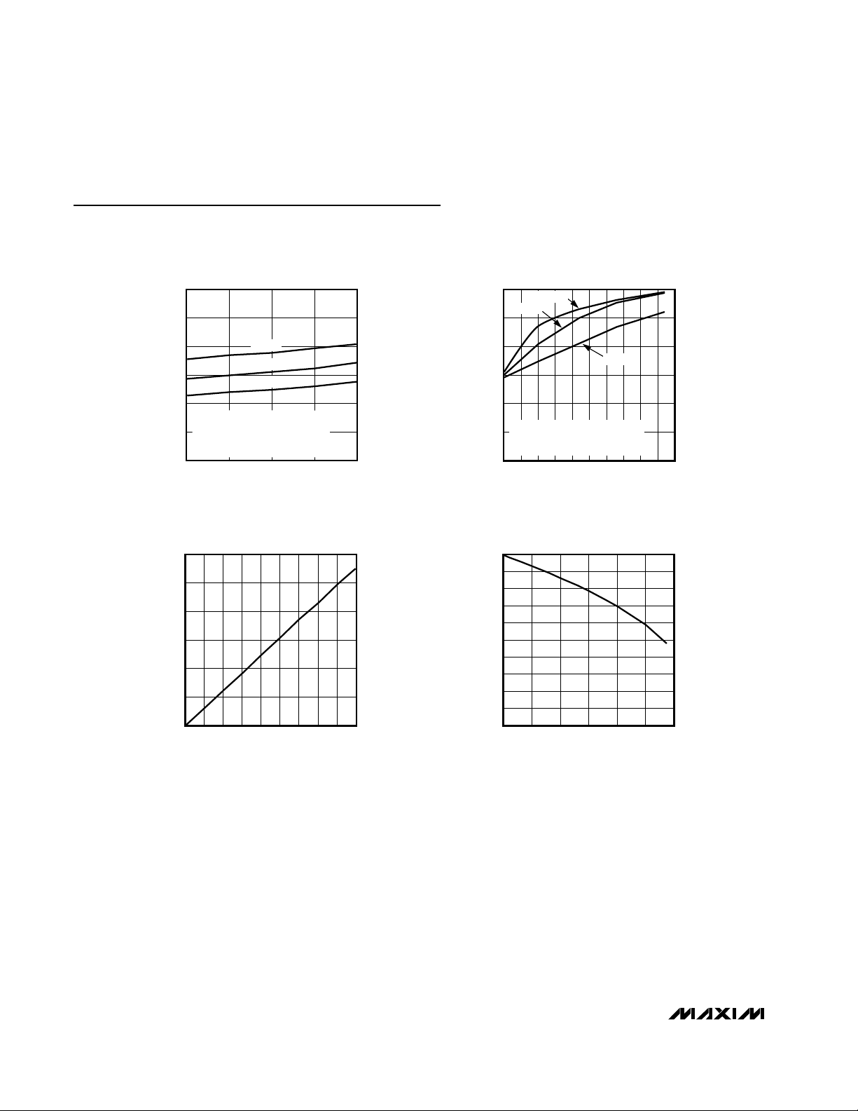
Typical Operating Characteristics
(V
STBY
= +5V, VDD= +12V, C1 = C2 = 0.1µF, TA = +25°C, unless otherwise noted.)
SUPPLY CURRENT vs. SUPPLY VOLTAGE
35
30
25
20
15
SUPPLY CURRENT (mA)
C1 = C2 = 0.1µF
2 TRANSMITTERS AT DATA RATE
10
4 TRANSMITTERS AT 1/16 DATA RATE
ALL TRANSMITTERS AT 3kΩ + 1000pF
5
10.8 12.011.4 12.6 13.2
RECEIVER OUTPUT LOW VOLTAGE
0.6
0.5
0.4
0.3
0.2
0.1
RECEIVER OUTPUT LOW VOLTAGE (V)
0
021 3456789
460kbps
240kbps
120kbps
SUPPLY VOLTAGE (V)
vs. SINK CURRENT
I
(mA)
SINK
MAX3209E-01
MAX3209E-03
SUPPLY CURRENT
vs. LOAD CAPACITANCE
30
25
20
15
10
SUPPLY CURRENT (mA)
5
0
460kbps
240kbps
120kbps
2 TRANSMITTERS AT DATA RATE
4 TRANSMITTERS AT 1/16 DATA RATE
3kΩ + C
L
0 20001000 3000 4000 5000
LOAD CAPACITANCE (pF)
RECEIVER OUTPUT HIGH VOLTAGE
vs. SOURCE CURRENT
5.0
4.5
4.0
3.5
3.0
2.5
2.0
1.5
1.0
RECEIVER OUTPUT HIGH VOLTAGE (V)
0.5
0
0105 15202530
I
(mA)
SOURCE
MAX3209E-02
MAX3209E-04
Page 5

Detailed Description
±15kV ESD Protection
As with all Maxim devices, ESD-protection structures
are incorporated on all pins to protect against electrostatic discharges (ESD) encountered during handling
and assembly. The MAX3209E driver outputs and
receiver inputs have extra protection against static
electricity found in normal operation. Maxim’s engineers developed state-of-the-art structures to protect
these pins against ±15kV ESD, without damage. After
an ESD event, the MAX3209E continues working without
latchup.
ESD protection can be tested in several ways. The
transmitter outputs and receiver inputs are characterized for protection to the following:
1) ±15kV using the Human Body Model
2) ±8kV using the Contact-Discharge Method specified
in IEC 1000-4-2 (formerly IEC 801-2)
3) ±15kV using the Air-Gap Method specified in
IEC 1000-4-2 (formerly IEC 801-2)
ESD Test Conditions
ESD performance depends on a number of conditions.
Contact Maxim for a reliability report that documents
test setup, methodology, and results.
Human Body Model
Figure 2a shows the Human Body Model, and Figure
2b shows the current waveform it generates when discharged into a low impedance. This model consists of
a 100pF capacitor charged to the ESD voltage of interest, which is then discharged into the device through a
1.5kΩ resistor.
IEC 1000-4-2
Since January 1996, all equipment manufactured
and/or sold in the European community has been
required to meet the stringent IEC 1000-4-2 specification. The IEC 1000-4-2 standard covers ESD testing
and performance of finished equipment; it does not
specifically refer to integrated circuits. The MAX3209E
helps you design equipment that meets Level 4 (the
highest level) of IEC 1000-4-2, without additional ESDprotection components.
The main difference between tests done using the
Human Body Model and IEC 1000-4-2 is higher peak
current in IEC 1000-4-2. Because series resistance is
lower in the IEC 1000-4-2 ESD test model (Figure 3a), the
ESD withstand voltage measured to this standard is generally lower than that measured using the Human Body
Model. Figure 3b shows the current waveform for the
±8kV IEC 1000-4-2 Level 4 ESD Contact-Discharge test.
The Air-Gap test involves approaching the device with a
charge probe. The Contact-Discharge method connects
the probe to the device before the probe is energized.
Machine Model
The Machine Model for ESD testing uses a 200pF storage capacitor and zero-discharge resistance. It mimics
the stress caused by handling during manufacturing
and assembly. Of course, all pins (not just RS-232
MAX3209E
±15kV ESD-Protected, 12V, Dual RS-232 Serial Port
with Low-Power Standby for Motherboards/Desktops
_______________________________________________________________________________________ 5
Pin Description
PIN
TSSOP QFN
1–5, 15–19 11–15, 36–40 R_OUT TTL/CMOS Receiver Outputs
6, 7, 8, 12, 13,
14
94V
10 5 V
11 6 C+ Positive Terminal of the Inverting Charge-Pump Capacitor
20–24, 34–38 16–20, 31–35 R_IN RS-232 Receiver Inputs
25, 26, 27, 31,
32, 33
28 25 GND Ground (for QFN package, connect the exposed pad and corner tabs to GND)
29 26 C- Negative Terminal of the Inverting Charge-Pump Capacitor
30 27 V- -12V Generated by the Inverting Charge Pump
— 10, 21 N.C. No Connection. Not internally connected.
1, 2, 3, 7, 8, 9 T_IN TTL/CMOS Transmitter Inputs
22, 24, 28, 30 T_OUT RS-232 Transmitter Outputs
NAME FUNCTION
STBY
DD
Standby Power Supply for R5 and R10
+12V Single-Supply Voltage
Page 6

MAX3209E
±15kV ESD-Protected, 12V, Dual RS-232 Serial Port
with Low-Power Standby for Motherboards/Desktops
6 _______________________________________________________________________________________
inputs and outputs) require this protection during manufacturing. Therefore, the Machine Model is less relevant to the I/O ports than are the Human Body Model
and IEC 1000-4-2.
±4kV Electrical Fast Transient/Burst Testing
(IEC 1000-4-4)
IEC 1000-4-4 Electrical Fast Transient/Burst (EFT/B) is
an immunity test for the evaluation of electrical and
electronic systems during operating conditions. The
test was adapted for evaluation of integrated circuits
with power applied. Repetitive fast transients with
severe pulsed EMI were applied to signal and control
ports. Over 15,000 distinct discharges per minute are
sent to each interface port of the IC or equipment under
test (EUT) simultaneously with a minimum test duration
time of one minute. This simulates stress due to displacement current from electrical transients on AC
mains, or other telecommunication lines in close proximity. Short rise times and very specific repetition rates
are essential to the validity of the test.
Stress placed on the EUT is severe. In addition to the
controlled individual discharges placed on the EUT,
extraneous noise and ringing on the transmission line
can multiply the number of discharges as well as
increase the magnitude of each discharge. All cabling
was left unterminated to simulate worst case reflections.
The MAX3209E was set up as specified in IEC 1000-4-4
and the Typical Operating Circuit of this data sheet.
The amplitude, pulse rise time, pulse duration, pulse
repetition period, burst duration, and burst period
(Figure 5) of the burst generator were all verified with a
Figure 1. Slew-Rate Test Circuit and Timing Diagram
Figure 3a. IEC 1000-4-2 ESD Test Model
Figure 2b. Human Body Model Current Waveform
Figure 2a. Human Body ESD Test Model
3.0V
DRIVER
INPUT
V
OUT
1.5V
0
t
PHL
3.3V
3.0V
-3.0V
-3.3V
R
C
1MΩ
CHARGE-CURRENT
HIGH-
DC
LIMIT RESISTOR
100pF
C
s
t
PLH
V
OH
VOLTAGE
0
SOURCE
R
D
1500Ω
DISCHARGE
RESISTANCE
STORAGE
CAPACITOR
DEVICE
UNDER
TEST
SIGNAL
GENERATOR
t
F2
t
F1
t
R2
t
R1
R
L
V
OL
C
L
PEAK-TO-PEAK RINGING
I
r
(NOT DRAWN TO SCALE)
AMPERES
IP 100%
90%
36.8%
10%
0
0
t
RL
TIME
t
DL
CURRENT WAVEFORM
HIGH-
VOLTAGE
DC
SOURCE
R
C
50MΩ to 100MΩ
CHARGE-CURRENT
LIMIT RESISTOR
C
150pF
s
R
D
330Ω
DISCHARGE
RESISTANCE
STORAGE
CAPACITOR
DEVICE
UNDER
TEST
Page 7

MAX3209E
±15kV ESD-Protected, 12V, Dual RS-232 Serial Port
with Low-Power Standby for Motherboards/Desktops
_______________________________________________________________________________________ 7
digital oscilloscope according to the specifications in
IEC 1000-4-4 sec. 6.1.1 and 6.1.2. A simplified diagram
of the EFT/B generator is shown in Figure 4. The burst
stresses were applied to R1IN–R10IN and T1OUT–
T6OUT simultaneously.
IEC 1000-4-4 provides several levels of test severity
(see Table 1). The MAX3209E passes the 4000V stress,
a special category “X” the beyond the highest level for
severe (transient) industrial environments for telecommunication lines.
The stresses are applied while the MAX3209E is powered up. Test results are reported as:
1) Normal performance within the specification limits.
2) Temporary degradation or loss of function or performance which is self-recoverable.
3) Temporary degradation, loss of function or performance requiring operator intervention, such as system reset.
4) Degradation or loss of function not recoverable due
to damage.
The MAX3209E meets classification 2 listed above.
Additionally, the MAX3209E will not latchup during the
IEC burst stress events.
Applications Information
R5 and R10 Active in Standby Mode
The MAX3209E is placed in standby mode when VDDis
not present, provided that V
STBY
remains at +3V to
+5.5V. In standby mode, receivers R5 and R10 remain
active, consuming 100µA max while unloaded. Standby
mode allows activity to be sensed on the serial ports so
that main power can be restored by the power-management unit, as shown in Figure 6.
Layout Considerations
Use proper layout to ensure other devices on your
board are not damaged in an ESD strike. Currents as
high as 60A can instantaneously pass into ground, so
be sure to minimize the ground-lead return path to the
power supply. A separate return path to the power supply is recommend. Trace widths should be greater than
40 mils. Bypass VDDand V
STBY
with 0.1µF capacitors
as close to the part as possible to ensure maximum
ESD protection.
The MAX3209E is not sensitive to power-supply
sequencing, and therefore requires no external protection diodes.
Interconnection with 3V and 5V Logic
The MAX3209E can directly interface with various 3V
and 5V logic families, including ACT and HCT CMOS.
See Table 2 for more information on possible combinations of interconnections.
Mouse Driveability
The MAX3209E has been specifically designed to
power serial mice while operating from low-voltage
power supplies. It has been tested with leading mouse
brands from manufacturers such as Microsoft and
Logitech. The MAX3209E successfully drove all serial
mice tested and met their respective current and voltage requirements.
Figure 3b. IEC 1000-4-2 ESD-Generator Current Waveform
Figure 4. Simplified circuit diagram of a fast transient/burst
generator
I
100%
90%
PEAK
I
10%
tR = 0.7ns to 1ns
30ns
60ns
t
C
D
SPARK-GAP
R
S
R
C
U
U = HIGH-VOLTAGE SOURCE
= CHARGING RESISTOR
R
C
= ENERGY STORAGE CAPACITOR
C
G
= PULSE-DURATION SHAPING RESISTOR
R
S
= IMPEDANCE MATCHING RESISTOR
R
M
= DC BLOCKING CAPACITOR
C
D
C
G
R
M
COAXIAL
OUTPUT
Page 8

MAX3209E
Chip Information
TRANSISTOR COUNT: 774
±15kV ESD-Protected, 12V, Dual RS-232 Serial Port
with Low-Power Standby for Motherboards/Desktops
8 _______________________________________________________________________________________
Table 1. Test Severity Levels for Communication Lines
SYSTEM POWER-
SUPPLY VOLTAGE
(V)
V
STBY
SUPPLY
VOLTAGE
(V)
COMPATIBILITY
3.3 3.3
Compatible with all
CMOS families.
5 5
Compatible with all
TTL and CMOS families.
5 3.3
Compatible with ACT
and HCT CMOS, and
with AC, HC, or
CD4000 CMOS.
Table 2. Logic Family Compatibility with
Various Supply Voltages
Figure 6. MAX3209E in Standby Mode
Figure 5. General Graph of a Fast Transient Burst
LEVEL
1 250 5 Well protected
2 500 5 Protected
3 1000 5 Typical
4 2000 5 Severe
X 4000 5 MAX3209E
ON I/O, SIGNAL, DATA,
AND CONTROL PORTS
PEAK VOLTAGE REPITITION RATE (kHz)
EFT
INDUSTRIAL ELECTROMAGNETIC
ENVIRONMENT
U
U
15ms
BURST DURATION
IMPULSION
PULSE
BURST
BURST PERIOD 300ms
+12V
POWER-MANAGEMENT UNIT
SUPER
I/O
R10
T_
V
STBY
MAX3209E
R5
ALL OTHER
RECEIVERS
R_
INACTIVE
ALL TRANSMITTERS
INACTIVE
GND
V
DD
Page 9

MAX3209E
±15kV ESD-Protected, 12V, Dual RS-232 Serial Port
with Low-Power Standby for Motherboards/Desktops
_______________________________________________________________________________________ 9
Typical Operating Circuit
37
36
35
34
33
32
31
30
29
28
27
26
25
24
2
3
4
5
6
7
8
9
10
11
12
13
14
15
R4IN
R3IN
R2IN
R1IN
T3OUT
T2OUT
R6IN
T1OUT
V-
C-
GND
T4OUT
T5OUT
T6OUT
R6OUT
T6IN
T5IN
T4IN
C+
V
DD
V
STBY
T1IN
T2IN
T3IN
R1OUT
R2OUT
R3OUT
R4OUT
381 R5INR5OUT
TSSOP
TOP VIEW
MAX3209E
23
22
21
20
16
17
18
19 R10IN
R7IN
R8IN
R9IN
R10OUT
R9OUT
R8OUT
R7OUT
Pin Configurations (continued)
0.1µF
TTL/CMOS
LOGIC
I/O
+5V
+12V +5V +12V
V
STBYVDD
T1
T2
T3
T4
T5
T6
0.1µF0.1µF
RS-232
R1
R2
R3
R4
R5
R6
R7
INTERCONNECTING
CABLE
V+
V+
V-
TX
V
CC
MAX3186MAX3209E
R1
R2
R3
T1
T2
T3
T4
T5
GND V
V
DD
-12V
MOUSE
SS
0.1µF
TTL/CMOS
LOGIC
I/O
0.1µF
C1
0.1µF
R8
R9
C1+
C1-
GND
R10
V-
0.1µF
C2
Page 10

MAX3209E
±15kV ESD-Protected, 12V, Dual RS-232 Serial Port
with Low-Power Standby for Motherboards/Desktops
10 ______________________________________________________________________________________
Package Information
(The package drawing(s) in this data sheet may not reflect the most current specifications. For the latest package outline information,
go to www.maxim-ic.com/packages.)
TSSOP, 4.40mm.EPS
Page 11

±15kV ESD-Protected, 12V, Dual RS-232 Serial Port
with Low-Power Standby for Motherboards/Desktops
MAX3209E
______________________________________________________________________________________ 11
Package Information (continued)
(The package drawing(s) in this data sheet may not reflect the most current specifications. For the latest package outline information,
go to www.maxim-ic.com/packages.)
36L,40L, QFN.EPS
Page 12

MAX3209E
±15kV ESD-Protected, 12V, Dual RS-232 Serial Port
with Low-Power Standby for Motherboards/Desktops
Maxim cannot assume responsibility for use of any circuitry other than circuitry entirely embodied in a Maxim product. No circuit patent licenses are
implied. Maxim reserves the right to change the circuitry and specifications without notice at any time.
12 __________________Maxim Integrated Products, 120 San Gabriel Drive, Sunnyvale, CA 94086 (408) 737-7600
© 2002 Maxim Integrated Products Printed USA is a registered trademark of Maxim Integrated Products.
Package Information (continued)
(The package drawing(s) in this data sheet may not reflect the most current specifications. For the latest package outline information,
go to www.maxim-ic.com/packages.)
 Loading...