

_______________General Description
The MAX3187 complete, dual DTE RS-232 serial port
meets the stringent ESD requirements of the European
Community. All transmitter outputs and receiver inputs
are protected to ±15kV using IEC 1000-4-2 Air-Gap
Discharge, ±8kV using IEC 1000-4-2 Contact
Discharge, and ±15kV using the Human Body Model.
The MAX3187’s six RS-232 transmitters and ten RS-232
receivers require no charge pump. Guaranteed to run
at data rates up to 230kbps, the MAX3187 is optimized
for desktop PC and motherboard applications, and is
compatible with popular software for PC communications. Power-supply current is less than 1mA for I
DD
and ISS, and less than 3mA for ICC.
The MAX3187 is available in a space-saving 36-pin
SSOP package.
________________________Applications
Desktop PC
Motherboards
Instruments
Equipment Meeting IEC 1000-4-2
____________________________Features
♦ Enhanced ESD Protection:
±15kV—Human Body Model
±8kV—IEC 1000-4-2, Contact Discharge
±15kV—IEC 1000-4-2, Air-Gap Discharge
♦ Latchup Free During an ESD Event
♦ 36-Pin SSOP Package
♦ Guaranteed 230kbps Data Rate
♦ Flow-Through Pinout
♦ Two Complete DTE Serial Ports
♦ 6 RS-232 Drivers and 10 RS-232 Receivers
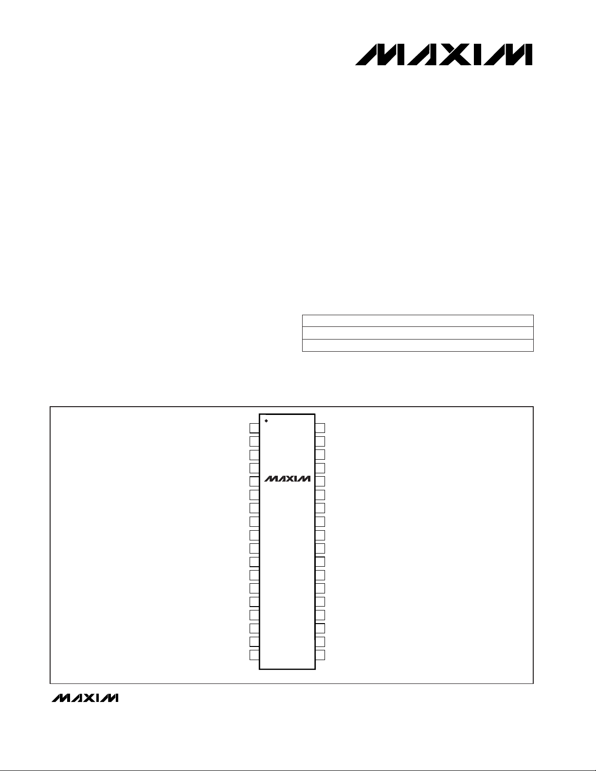
MAX3187
±15kV ESD-Protected, EMC-Compliant, 230kbps,
Dual RS-232 Serial Port for Motherboards/Desktops
________________________________________________________________
Maxim Integrated Products
1
35
34
33
32
31
30
29
28
27
26
25
24
23
3
4
5
6
7
8
9
10
11
12
13
14
R3IN
T1OUT
T2OUT
R4IN
T4OUT
T3OUT
R5IN
V
DD
GND
R6IN
R7IN
R8IN
T4IN
R8OUT
R7OUT
R6OUT
V
SS
V
CC
R5OUT
T3IN
R4OUT
T2IN
T1IN
R3OUT
361 R1INR1OUT
2 R2INR2OUT
SSOP
TOP VIEW
MAX3187
22
21
15
16
T5OUT
R9IN
1918 R10INR10OUT
2017 T6OUTT6IN
R90UT
T5IN
19-1186; Rev 1; 10/98
PART
MAX3187CAX
MAX3187EAX -40°C to +85°C
0°C to +70°C
TEMP. RANGE PIN-PACKAGE
36 SSOP
36 SSOP
______________Ordering Information
For free samples & the latest literature: http://www.maxim-ic.com, or phone 1-800-998-8800
For small orders, phone 1-800-835-8769.
____________________________________________________________Pin Configuration
Typical Operating Circuit appears at end of data sheet.
MAX3187
±15kV ESD-Pr otected, EMC-Compliant, 230kbps,
Dual RS-232 Serial Port for Motherboards/Desktops
2 _______________________________________________________________________________________
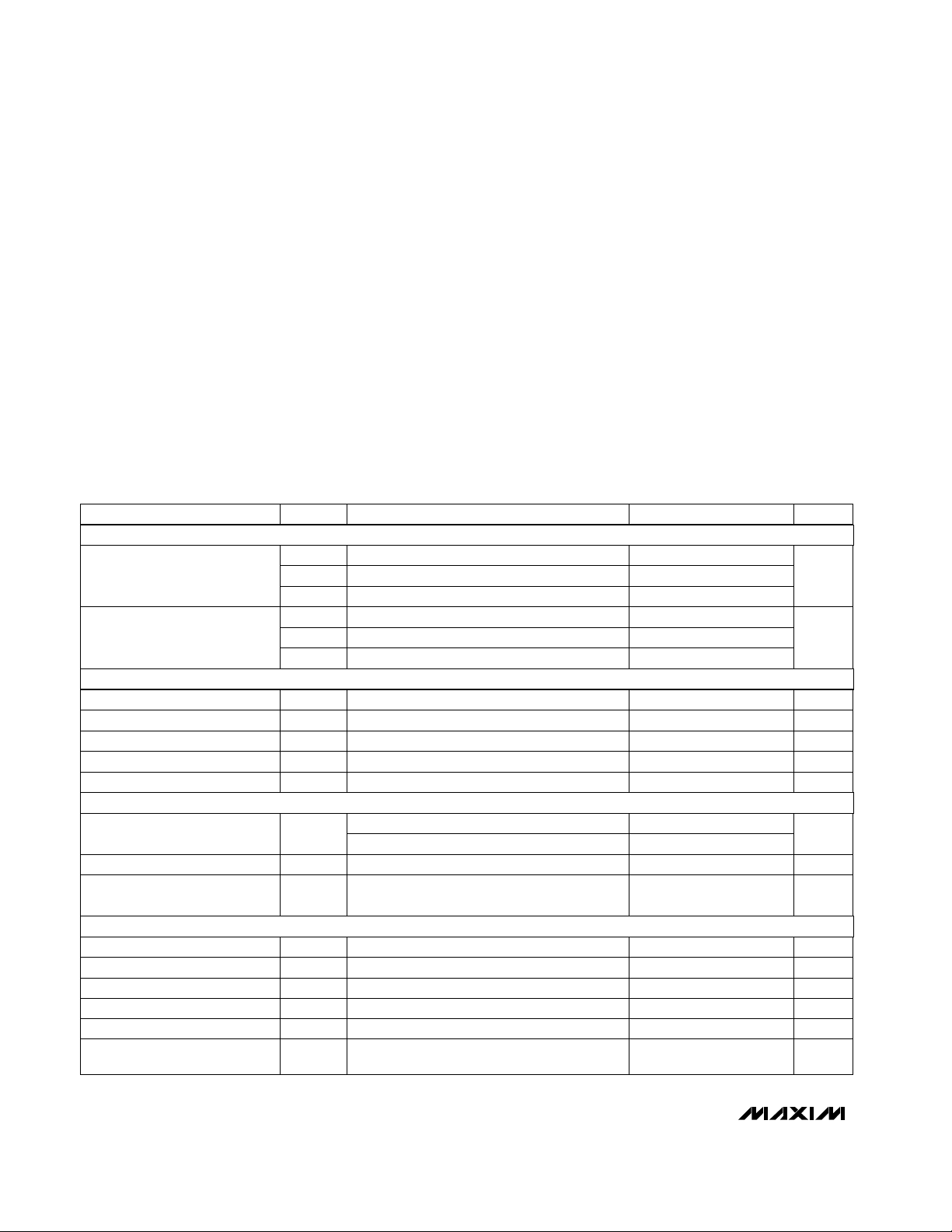
ABSOLUTE MAXIMUM RATINGS
ELECTRICAL CHARACTERISTICS
(VCC= +4.5V to +5.5V, VDD= +10.8V to +13.2V, VSS= -10.8V to -13.2V, TA= T
MIN
to T
MAX
, unless otherwise noted. Typical values
are at TA= +25°C.)
Stresses beyond those listed under “Absolute Maximum Ratings” may cause permanent damage to the device. These are stress ratings only, and functional
operation of the device at these or any other conditions beyond those indicated in the operational sections of the specifications is not implied. Exposure to
absolute maximum rating conditions for extended periods may affect device reliability.
VCC...........................................................................-0.3V to +7V
V
DD
.........................................................................-0.3V to +14V
V
SS
......................................................................... +0.3V to -14V
Input Voltages
T_IN......................................................................-0.3V to +6V
R_IN.................................................................................±30V
Output Voltages
T_OUT..............................................................................±15V
R_OUT....................................................-0.3V to (V
CC
+ 0.3V)
Short-Circuit Duration
T_OUT (one at a time)............................................Continuous
R_OUT (one at a time)............................................Continuous
Continuous Power Dissipation (T
A
= +70°C)
SSOP (derate 11.76mW/°C above +70°C) ..................762mW
Operating Temperature Ranges
MAX3187CAX .....................................................0°C to +70°C
MAX3187EAX ..................................................-40°C to +85°C
Storage Temperature Range ............................-65°C to +160°C
Lead Temperature (soldering, 10sec) ............................+300°C
VCC= VDD= VSS= 0, V
T_OUT
= ±2V
VDD= 12V, VSS= -12V, RL= 3kΩ
T_IN
VDD= 7.0V, VSS= -7.0V, RL= 3kΩ
T_IN
No load
No load
R_OUT; I
SOURCE
= 1mA
No load
R_OUT; I
SINK
= 3.2mA
CONDITIONS
V2.4RS-232 Input Threshold High
V0.75RS-232 Input Threshold Low
V-25 25Receiver Input Voltage Range
mA±35 ±60
RS-232 Output Short-Circuit
Current
Ω300Transmitter Output Resistance
V
±9.5
Output Voltage Swing
±5.0
VVCC- 0.6V
OHR
Output Voltage High
V0.4V
OLR
Output Voltage Low
10.8 13.2V
DD
4.5 5.5V
CC
µA0.01 1Input Leakage Current
V2.0V
IHT
Input Logic Threshold High
V0.8V
ILT
Input Logic Threshold Low
V
-13.2 -10.8V
SS
Operating Voltage Range
750 3000I
CC
370 1000I
DD
µA
370 1000I
SS
Supply Current
UNITSMIN TYP MAXSYMBOLPARAMETER
V0.65RS-232 Input Hysteresis
kΩ3 5 7RS-232 Input Resistance
mA±10
Receiver Output Short-Circuit
Current
RECEIVER INPUTS
TRANSMITTER OUTPUTS
LOGIC
DC CHARACTERISTICS
MAX3187
±15kV ESD-Pr otected, EMC-Compliant, 230kbps,
Dual RS-232 Serial Port for Motherboards/Desktops
_______________________________________________________________________________________ 3
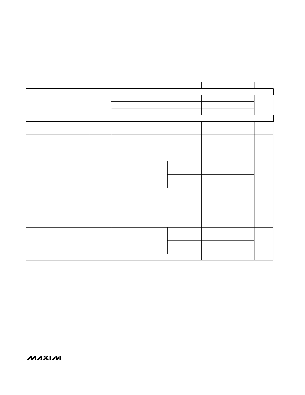
ELECTRICAL CHARACTERISTICS (continued)
(VCC= +4.5V to +5.5V, VDD= +10.8V to +13.2V, VSS= -10.8V to -13.2V, TA= T
MIN
to T
MAX
, unless otherwise noted. Typical values
are at TA= +25°C.)
VDD= 12V, VSS= -12V, RL= 3kΩ,
CL= 1000pF, TA= +25°C
VDD= 12V, VSS= -12V,
RL= 3kΩ to 7kΩ,
measured from +3V to -3V
or -3V to +3V,
Figure 1, TA= +25°C
IEC 1000-4-2 (Contact Discharge)
4
Human Body Model
t
PHLT
8 30
µs
SR
Transmitter Output
Propagation Delay, High to Low
V/µsTransition Output Slew Rate
IEC 1000-4-2 (Air-Gap Discharge)
VCC= 5V, CL= 50pF, TA= +25°C
VCC= 5V, CL= 50pF, TA= +25°C
CL= 50pF to
1000pF
4.0
4.0
CONDITIONS
t
PHLR
CL= 50pF to
2500pF
µs
VDD= 12V, VSS= -12V, RL= 3kΩ,
CL= 1000pF, TA= +25°C
Receiver Output
Propagation Delay, High to Low
t
PLHR
4
µs
t
PLHT
Receiver Output
Propagation Delay, Low to High
µs
Transmitter Output
Propagation Delay, Low to High
T3OUT = -5mA, T1OUT = T2OUT = 5mA
120
±7.5 VMouse Driveability
VCC= 5V, CL= 50pF, TA= +25°C 0.4t
SKR
µs
Receiver Propagation Delay
Skew,
|
t
PLHR
- t
PHLR
|
VCC= 5V, VDD= 12V,
VSS= -12V,
RL= 3kΩ to 7kΩ,
TA= +25°C, any two
transmitters switching
230
kbpsDRGuaranteed Data Rate
±8
±15
VDD= 12V, VSS= -12V, RL= 3kΩ,
CL= 1000pF, TA= +25°C
0.4t
SKT
µs
Transmitter Propagation Delay
Skew,
|
t
PLHT
- t
PHLT
|
CL= 50pF to
1000pF
4 30
CL= 150pF to
2500pF
kV
±15
ESD Protection
UNITSMIN TYP MAXSYMBOLPARAMETER
ESD CHARACTERISTICS
TIMING CHARACTERISTICS

MAX3187
±15kV ESD-Pr otected, EMC-Compliant, 230kbps,
Dual RS-232 Serial Port for Motherboards/Desktops
4 _______________________________________________________________________________________
__________________________________________Typical Operating Characteristics
(VCC= +5V, VDD= +12V, VSS= -12V, TA = +25°C, unless otherwise noted.)
40
-40
SUPPLY CURRENT
vs. LOAD CAPACITANCE
20
MAX3187/TOC-01
SUPPLY CURRENT (mA)
0 1000 3000
LOAD CAPACITANCE (pF)
2000 4000 5000
0
-20
30
10
-10
-30
IDD, 240kbps
IDD, 20kbps
ISS, 20kbps
ISS, 120kbps
ISS, 240kbps
I
CC
IDD, 120kbps
2 TRANSMITTERS AT DATA RATE
4 TRANSMITTERS AT DATA RATE/16
3kΩ + C
LOAD
40
-40
10.8
SUPPLY CURRENT
vs. SUPPLY VOLTAGE
20
MAX3187/TOC-02
SUPPLY VOLTAGE (±V)
SUPPLY CURRENT (mA)
12.011.4 12.6 13.2
0
-20
30
10
-10
-30
IDD, 240kbps
IDD, 20kbps
I
SS,
20kbps
I
SS,
120kbps
I
SS,
240kbps
I
CC
IDD, 120kbps
4 TRANSMITTERS AT DATA RATE/16
3kΩ + C
LOAD
VCC = 5V
2 TRANSMITTERS AT DATA RATE
16
0
0 1000 3000
SLEW RATE
vs. LOAD CAPACITANCE
12
MAX3187/TOC-03
LOAD CAPACITANCE (pF)
SLEW RATE (V/µs)
2000 4000 5000
8
4
14
10
6
2
2 TRANSMITTERS AT DATA RATE
4 TRANSMITTERS AT DATA RATE/16
3kΩ + C
LOAD
RISE
FALL
TRANSMITTER OUTPUT VOLTAGE
vs. LOAD CAPACITANCE
MAX3187/TOC-04
LOAD CAPACITANCE (pF)
TRANSMITTER OUTPUT VOLTAGE (V)
12.5
10.0
7.5
5.0
2.5
0
-2.5
-5.0
-7.5
-10.0
-12.5
4000 50003000200010000
240kbps
120kbps
120kbps
240kbps
2 TRANSMITTER, 240kbps
4 TRANSMITTERS, 15kbps
3kΩ + C
LOAD
TRANSMITTER OUTPUT VOLTAGE vs.
LOAD CURRENT PER TRANSMITTER
MAX3187/TOC-05
LOAD CURRENT PER TRANSMITTER (mA)
TRANSMITTER OUTPUT VOLTAGE (V)
15
10
5
0
-5
-10
-15
10 12 14 16 186 82 4
0
V
OUT+
V
OUT-
T1
V
CC
V
OUT+
V
OUT-
T2
T3
SLEW RATE
vs. TEMPERATURE
MAX3187/TOC-06
TEMPERATURE (°C)
SLEW RATE (V/ms)
25
20
15
10
5
0
85 105 12545 655 25-35 -15-55
RISE, 500pF
FALL, 500pF
RISE, 2000pF
FALL, 2000pF

_______________Detailed Description
±15kV ESD Protection
As with all Maxim devices, ESD-protection structures
are incorporated on all pins to protect against electrostatic discharges (ESD) encountered during handling
and assembly. The MAX3187 driver outputs and receiver inputs have extra protection against static electricity
found in normal operation. Maxim’s engineers developed state-of-the-art structures to protect these pins
against ±15kV ESD, without damage. After an ESD
event, the MAX3187 continues working without latchup.
ESD protection can be tested in several ways. The
transmitter outputs and receiver inputs are characterized for protection to the following:
1) ±15kV using the Human Body Model
2) ±8kV using the Contact-Discharge Method specified
in IEC 1000-4-2 (formerly IEC 801-2)
3) ±15kV using the Air-Gap Method specified in
IEC 1000-4-2 (formerly IEC 801-2)
ESD Test Conditions
ESD performance depends on a number of conditions.
Contact Maxim for a reliability report that documents
test setup, methodology, and results.
MAX3187
±15kV ESD-Pr otected, EMC-Compliant, 230kbps,
Dual RS-232 Serial Port for Motherboards/Desktops
_______________________________________________________________________________________ 5
______________________________________________________________Pin Description
PIN NAME FUNCTION
4, 5, 7, 14, 15, 17 T1IN–T6IN Transmitter Inputs
9 V
CC
Supply-Voltage Input, 4.5V to 5.5V
27 GND Ground. Connect system to ground.
1, 2, 3, 6, 8, 11,
12, 13, 16, 18
R1OUT–R10OUT Receiver Outputs, swing between GND and V
CC
10 V
SS
Supply-Voltage Input, -10.8V to -13.2V
28 V
DD
Supply-Voltage Input, 10.8V to 13.2V
19, 21, 24, 25, 26,
29, 31, 34, 35, 36
R10IN–R1IN Receiver Inputs
20, 22, 23, 30, 32, 33 T6OUT–T1OUT Transmitter Outputs, swing between VDDand V
SS
Figure 1. Slew-Rate Test Circuit and Timing Diagram
3.0V
DRIVER
INPUT
0V
V
OUT
GENERATOR
SIGNAL
1.5V
t
PHL
t
F2
t
F1
3.3V
3.0V
-3.0V
-3.3V
t
PLH
t
R2
t
R1
R
L
C
L
V
OH
0V
V
OL

MAX3187
±15kV ESD-Pr otected, EMC-Compliant, 230kbps,
Dual RS-232 Serial Port for Motherboards/Desktops
6 _______________________________________________________________________________________
Human Body Model
Figure 2a shows the Human Body Model, and Figure
2b shows the current waveform it generates when discharged into a low impedance. This model consists of
a 100pF capacitor charged to the ESD voltage of interest, which is then discharged into the device through a
1.5kΩ resistor.
IEC 1000-4-2
Since January 1996, all equipment manufactured
and/or sold in the European community has been
required to meet the stringent IEC 1000-4-2 specification. The IEC 1000-4-2 standard covers ESD testing
and performance of finished equipment; it does not
specifically refer to integrated circuits. The MAX3187
helps you design equipment that meets Level 4 (the
highest level) of IEC 1000-4-2, without additional ESDprotection components.
The main difference between tests done using the
Human Body Model and IEC 1000-4-2 is higher peak
current in IEC 1000-4-2. Because series resistance is
lower in the IEC 1000-4-2 ESD test model (Figure 3a), the
ESD withstand voltage measured to this standard is generally lower than that measured using the Human Body
Model. Figure 3b shows the current waveform for the
±8kV IEC 1000-4-2 Level 4 ESD Contact-Discharge test.
The Air-Gap test involves approaching the device with a
charge probe. The Contact-Discharge method connects
the probe to the device before the probe is energized.
CHARGE-CURRENT
LIMIT RESISTOR
DISCHARGE
RESISTANCE
STORAGE
CAPACITOR
C
s
100pF
R
C
1M
R
D
1500Ω
HIGH-
VOLTAGE
DC
SOURCE
DEVICE
UNDER
TEST
Figure 3a. IEC 1000-4-2 ESD Test Model
Figure 3b. IEC 1000-4-2 ESD-Generator Current Waveform
Figure 2b. Human Body Model Current Waveform
Figure 2a. Human Body ESD Test Model
R
C
50M to 100M
CHARGE-CURRENT
LIMIT RESISTOR
HIGH-
VOLTAGE
DC
SOURCE
150pF
C
s
R
D
330Ω
DISCHARGE
RESISTANCE
STORAGE
CAPACITOR
DEVICE
UNDER
TEST
PEAK-TO-PEAK RINGING
I
r
(NOT DRAWN TO SCALE)
AMPERES
IP 100%
90%
36.8%
10%
0
0
t
RL
TIME
t
DL
CURRENT WAVEFORM
I
100%
90%
PEAK
I
10%
tr = 0.7ns to 1ns
30ns
60ns
t

MAX3187
±15kV ESD-Pr otected, EMC-Compliant, 230kbps,
Dual RS-232 Serial Port for Motherboards/Desktops
_______________________________________________________________________________________ 7
TRANSISTOR COUNT: 419
___________________Chip Information
Machine Model
The Machine Model for ESD testing uses a 200pF storage capacitor and zero-discharge resistance. It mimics
the stress caused by handling during manufacturing
and assembly. Of course, all pins (not just RS-232
inputs and outputs) require this protection during manufacturing. Therefore, the Machine Model is less relevant to the I/O ports than are the Human Body Model
and IEC 1000-4-2.
Applications Information
Use proper layout to ensure other devices on your
board are not damaged in an ESD strike. Currents as
high as 60A can instantaneously pass into ground, so
be sure to minimize the ground-lead return path to the
power supply. A separate return path to the power supply is recommend. Trace widths should be greater than
40 mils. Bypass VCC, VDD, and VSSwith 0.1µF capacitors as close to the part as possible to ensure maximum ESD protection.
Connect any unused transmitter inputs to GND or VCC.
The MAX3187 is not sensitive to power-supply
sequencing, and therefore requires no external protection diodes.
RS-232
INTERCONNECTING
CABLE
T1
T2
T3
T4
T5
R1
R2
T3
T4
T5
R3
R4
R5
R8
R9
R10
R2
R1
R3
T1
T2
TTL/CMOS
LOGIC
I/O
TTL/CMOS
LOGIC
I/O
MOUSE
V+
GND V
SS
GND V
SS
0.1µF
0.1µF
-12V
V+
V-
TX
T6
R6
-12V
0.1µF
0.1µF0.1µF
+5V
V
CC
V
DD
MAX3186MAX3187
V
CCVDD
+12V +5V +12V
0.1µF
R7
__________Typical Operating Circuit

Maxim cannot assume responsibility for use of any circuitry other than circuitry entirely embodied in a Maxim product. No circuit patent licenses are
implied. Maxim reserves the right to change the circuitry and specifications without notice at any time.
8
_____________________Maxim Integrated Products, 120 San Gabriel Drive, Sunnyvale, CA 94086 408-737-7600
© 1998 Maxim Integrated Products Printed USA is a registered trademark of Maxim Integrated Products.
MAX3187
±15kV ESD-Pr otected, EMC-Compliant, 230kbps,
Dual RS-232 Serial Port for Motherboards/Desktops
________________________________________________________Package Information
SSOP.EPS
 Loading...