

Page 1
MAX291, MAX292, MAX295, MAX296 八阶、低通、开关电容滤波器 - 概述
ENGLISH • 简体中文 • 日本語 • 한국어
Login | Register
请输入关键词或器件型号
最新内容 产品 方案 设计 应用 技术支持 销售联络 公司简介 我的Maxim
Maxim > 产品 > 滤波器(模拟) > MAX291, MAX292, MAX295, MAX296
MAX291, MAX292, MAX295, MAX296
八阶、低通、开关电容滤波器
请参考MAX7401/MAX7405 8阶、低功耗贝塞尔滤波器
概述 技术文档 定购信息 用户说明 (0) 所有内容
状况
状况:生产中。
概述
The MAX291/MAX292/MAX295/MAX296 are easy -to- use, 8th-order, lowpass, switched -capacitor filters that
can be set up with corner frequencies from 0.1Hz to 25kHz (MAX291/MAX292) or 0.1Hz to 50kHz
(MAX295/MAX296).
The MAX291/MAX295 Butterworth filters provide maximally flat passband response, and the
MAX292/MAX296 Bessel filters provide low overshoot and fast settling. All four filters have fixed responses, so the design task is limited to
selecting the clock frequency that controls the filter's corner frequency.
完整的数据资料
英文
下载
Rev. 4 (PDF, 196kB)
An external capacitor is used to generate a clock using the internal oscillator, or an external clock signal can be used. An uncommitted operational
amplifier (noninverting input grounded) is provided for building a continuous time lowpass filter for post - filtering or anti-aliasing.
Produced in an 8- pin DIP/SO and a 16-pin wide SO package, and requiring a minimum of external components, the MAX291 series delivers very
aggressive performance from a tiny area.
关键特性 应用/使用
8th-Order Lowpass Filters:
Butterworth (MAX291/MAX295)
Bessel (MAX292/MAX296)
Clock- Tunable Corner - Frequency Range:
50Hz/60Hz电源噪声滤波
ADC抗混叠滤波器
DAC后置滤波
噪声分析
0.1Hz to 25kHz (MAX291/MAX292)
0.1Hz to 50kHz (MAX295/MAX296)
No External Resistors or Capacitors Required
Internal or External Clock
Clock to Corner Frequency Ratio:
100:1 (MAX291/MAX292)
50:1 (MAX295/MAX296)
Low Noise: -70dB THD + Noise (Typ)
Operate with a Single +5V Supply or Dual ±5V Supplies
Uncommitted Op Amp for Anti -Aliasing or Clock- Noise Filtering
8-Pin DIP and SO Packages
Key Specifications: Active Filters
25
V
SUPPLY
(Dual)
(±V)
5 5
V
SUPPLY
(V)
Oper. Temp.
(°C)
-55 to +125
-40 to +85
0 to +70
Price
See
Notes
$2.95
@1k
$2.95
@1k
$2.95
@1k
Lowest
Cutoff
Part
Number
Filter
Sections
Order
Per
Filter
Filter
Class
Filter
Type
Filter
Characteristic
Program
Method
Section
MAX291
MAX292 Bessel 25
1 8
MAX295 Butterworth 50
Switched
Cap
Lowpass
Butterworth
Clock 0.1
Highest
Cutoff
(Hz)
(kHz)
max min Dual
http://china.maxim-ic.com/datasheet/index.mvp/id/1370[2010-08-31 8:33:14]
Page 2
MAX291, MAX292, MAX295, MAX296 八阶、低通、开关电容滤波器 - 概述
$2.95
MAX296 Bessel 50
查看所有Active Filters (50)
图表
典型工作电路
注释、注解
Single 8th- order, lowpass, switched - capacitor filter
@1k
相关产品
MAX7409,
五阶、低通、开关电容滤波器
MAX7410,
MAX7413, ...
MAX7401, MAX7405 八阶、低通、贝塞尔、开关电容滤波器
类似产品:浏览其它类似产品线
查看所有Active Filters (50产品)
没有找到你需要的产品吗?
应用工程师帮助选型,下个工作日回复
参数搜索
应用帮助
概述 技术文档 定购信息
概述
关键特性
应用/使用
关键指标
图表
注释、注解
相关产品
数据资料
应用笔记
评估板
设计指南
可靠性报告
软件/模型
参考文献: 19-4526 Rev. 4; 2009-09-03
本页最后一次更新: 2010- 04-20
价格与供货
样品
在线订购
封装信息
无铅信息
联络我们:信息反馈、提出问题 • 对该网页的评价 • 发送本网页 • 隐私权政策 • 法律声明
© 2010 Maxim Integrated Products 版权所有
http://china.maxim-ic.com/datasheet/index.mvp/id/1370[2010-08-31 8:33:14]
Page 3
General Description
The MAX291/MAX292/MAX295/MAX296 are easy-to-use,
8th-order, lowpass, switched-capacitor filters that can be
set up with corner frequencies from 0.1Hz to 25kHz
(MAX291/MAX292) or 0.1Hz to 50kHz (MAX295/MAX296).
The MAX291/MAX295 Butterworth filters provide maximally flat passband response, and the MAX292/MAX296
Bessel filters provide low overshoot and fast settling. All
four filters have fixed responses, so the design task is
limited to selecting the clock frequency that controls the
filter’s corner frequency.
An external capacitor is used to generate a clock using
the internal oscillator, or an external clock signal can be
used. An uncommitted operational amplifier (noninverting
input grounded) is provided for building a continuoustime lowpass filter for post-filtering or anti-aliasing.
Produced in an 8-pin DIP/SO and a 16-pin wide SO
package, and requiring a minimum of external components, the MAX291 series delivers very aggressive performance from a tiny area.
Applications
ADC Anti-Aliasing Filter
Noise Analysis
DAC Post-Filtering
50Hz/60Hz Line-Noise Filtering
Features
o 8th-Order Lowpass Filters:
Butterworth (MAX291/MAX295)
Bessel (MAX292/MAX296)
o Clock-Tunable Corner-Frequency Range:
0.1Hz to 25kHz (MAX291/MAX292)
0.1Hz to 50kHz (MAX295/MAX296)
o No External Resistors or Capacitors Required
o Internal or External Clock
o Clock to Corner Frequency Ratio:
100:1 (MAX291/MAX292)
50:1 (MAX295/MAX296)
o Low Noise: -70dB THD + Noise (Typ)
o Operate with a Single +5V Supply or
Dual ±5V Supplies
o Uncommitted Op Amp for Anti-Aliasing or Clock-
Noise Filtering
o 8-Pin DIP and SO Packages
8th-Order, Lowpass,
Switched-Capacitor Filters
________________________________________________________________
Maxim Integrated Products
1
19-4526; Rev 5; 5/10
MAX291/MAX292/MAX295/MAX296
Ordering Information
Pin Configurations
Ordering Information continued at end of data sheet.
* Contact factory for dice specifications.
** Contact factory for availability and processing to MIL-STD-883.
PART TEMP. RANGE PIN-PACKAGE
MAX291CPA
MAX291CWE
0°C to +70°C 8 Plastic DIP
MAX291C/D 0°C to +70°C
0°C to +70°C 16 Wide SO
Dice*
MAX291EPA -40°C to +85°C 8 Plastic DIP
MAX291EWE
MAX291MJA -55°C to +125°C
-40°C to +85°C 16 Wide SO
8 CERDIP**
16-pin Wide SO at end of data sheet.
MAX291CSA 0°C to +70°C 8 SO
MAX291ESA -40°C to +85°C 8 SO
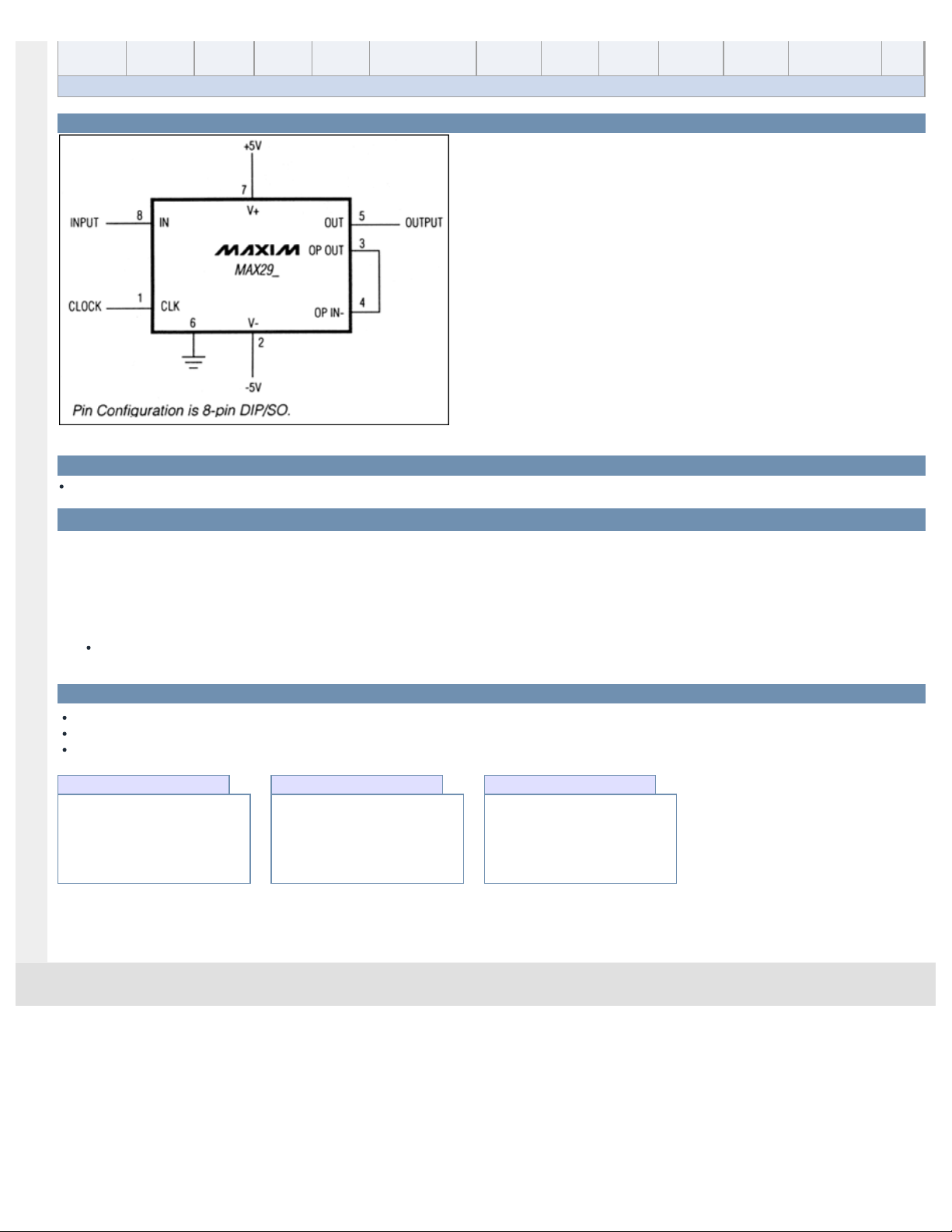
Typical Operating Circuit
Pin Configuration is 8-pin DIP/SO.
For pricing, delivery, and ordering information, please contact Maxim Direct at 1-888-629-4642,
or visit Maxim’s website at www.maxim-ic.com.
+5V
7
INPUT IN
CLOCK CLK
8
1
6
V+
MAX29_
V-
2
-5V
5
OUT OUTPUT
3
OP OUT
4
OP IN-
TOP VIEW
CLK
V-
OP OUT
OP IN-
1
2
MAX29_
3
4
DIP/SO
8
IN
7
V+
6
GND
5
OUT
Page 4
MAX291/MAX292/MAX295/MAX296
8th-Order, Lowpass,
Switched-Capacitor Filters
2 _______________________________________________________________________________________
ABSOLUTE MAXIMUM RATINGS
ELECTRICAL CHARACTERISTICS
(V+ = 5V, V- = -5V, filter output measured at OUT pin, 20kΩ load resistor to ground at OUT and OP OUT, f
CLK
= 100kHz
(MAX291/MAX292) or f
CLK
= 50kHz (MAX295/MAX296), TA= T
MIN
to T
MAX
, unless otherwise noted.)
Stresses beyond those listed under “Absolute Maximum Ratings” may cause permanent damage to the device. These are stress ratings only, and functional
operation of the device at these or any other conditions beyond those indicated in the operational sections of the specifications is not implied. Exposure to
absolute maximum rating conditions for extended periods may affect device reliability.
Supply Voltage (V+ to V-).......................................................12V
Input Voltage at Any Pin.............V- + (-0.3V) ≤ V
IN
≤ V+ + (0.3V)
Continuous Power Dissipation
8-Pin Plastic DIP (derate 9.09mW/°C above +70°C) ...727mW
8-Pin SO (derate 5.88mW/°C above +70°C)................471mW
16-Pin Wide SO (derate 9.52mW/°C above +70°C) ....762mW
8-Pin CERDIP (derate 8.00mW/°C above +70°C)........640mW
Operating Temperature Ranges
MAX29_C_ _........................................................0°C to +70°C
MAX29_E_ _ .....................................................-40°C to +85°C
MAX29_MJA ..................................................-55°C to +125°C
Storage Temperature Range .............................-65°C to +160°C
Lead Temperature (soldering, 10s) .................................+300°C
Soldering Temperature (reflow) .......................................+240°C
MAX295/MAX296
MAX291/MAX292
MAX296
MAX295
MAX291/MAX292
MAX295/MAX296
MAX291
MAX292
CONDITIONS
Hz
0.1-50k
Corner-Frequency Range
0.1-25k
-0.02 -0.1
60
Clock to Corner
Frequency Tempco
5
100:1
50:1
Clock to Corner
Frequency Ratio
10
40
UNITSMIN TYP MAXPARAMETER
fIN= 0.50 F
o
fIN= 1.00 F
o
-2.2 -2.7 -3.2
MAX291
fIN= 3.00 F
o
-70.0 -76.0
fIN= 2.00 F
o
-43.0 -48.0
fIN= 0.50 F
o
-0.6 -0.8 -1.0
fIN= 2.00 F
o
-11.0 -13.0 -15.0
fIN= 1.00 F
o
-2.7 -3.0 -3.3
fIN= 0.25 F
o
-0.1 -0.2 -0.3
fIN= 3.00 F
o
-30.0 -34.0
MAX292
fIN= 6.00 F
o
-74.0 -78.0
fIN= 4.00 F
o
-47.0 -51.0
fIN= 1.00 F
o
-2.2 -2.7 -3.2
MAX295
fIN= 3.00 F
o
-70.0 -76.0
fIN= 2.00 F
o
-43.0 -48.0
fIN= 0.50 F
o
fIN= 0.50 F
o
-0.6 -0.8 -1.0
fIN= 2.00 F
o
-11.0 -13.0 -15.0
fIN= 1.00 F
o
-2.7 -3.0 -3.3
fIN= 0.25 F
o
-0.1 -0.2 -0.3
fIN= 3.00 F
o
-30.0 -34.0
MAX296
fIN= 6.00 F
o
-74.0 -78.0
Insertion Gain Relative to
DC Gain
fIN= 4.00 F
o
-47.0 -51.0
-0.02 -0.1
dB
ppm/°C
FILTER CHARACTERISTICS
Page 5

MAX291/MAX292/MAX295/MAX296
8th-Order, Lowpass,
Switched-Capacitor Filters
_______________________________________________________________________________________ 3
ELECTRICAL CHARACTERISTICS (continued)
(V+ = 5V, V- = -5V, filter output measured at OUT pin, 20kΩ load resistor to ground at OUT and OP OUT, f
CLK
= 100kHz
(MAX291/MAX292) or f
CLK
= 50kHz (MAX295/MAX296), TA= T
MIN
to T
MAX
, unless otherwise noted.)
IN = GND
V+ = 5V, V- = -5V, V
CLK
= 0V to 5V
V- = 0V, GND = V±2
V
CLK
= 0V or 5V
TA= +25°C, f
CLK
= 100kHz
f
CLK
= 100kHz
C
OSC
= 1000pF
CONDITIONS
mA
15 22
4.750 11.000Single Supply
V±2.375 ±5.500
Supply Voltage
Dual Supply
µA0.05Input Bias Current
V±4Output DC Swing
mV±10 ±50Input Offset Voltage
dB0.15 0 -0.15
DC Insertion Gain Error with
Output Offset Removed
mV±150 ±400
V±4Output DC Swing
Output Offset Voltage
1.0Low
V4.0
Clock Input High
(Note 1)
µA±70 ±120
Internal Oscillator
Current Source/Sink
dB-70
Total Harmonic Distortion
plus Noise
mVp-p6Clock Feedthrough
kHz29 35 43
Internal Oscillator
Frequency
UNITSMIN TYP MAXPARAMETER
V+ = 2.375V, V- = -2.375V, V
CLK
= -2V to 2V 712
Supply Current
CLOCK
UNCOMMITTED OP AMP
POWER REQUIREMENTS
V
V
Typical Operating Characteristics
(V+ = 5V, V- = -5V, TA= +25°C, f
CLK
= 100kHz (MAX291/MAX292) or f
CLK
= 50kHz (MAX295/MAX296), unless otherwise noted.)
0.990
1.000
1.020
1.010
1.030
2.0 3.5 4.02.5 3.0 4.5 5.0 5.5
NORMALIZED INTERNAL OSCILLATOR
FREQUENCY vs. SUPPLY VOLTAGE
MAX291/2/5/6-02
SUPPLY VOLTAGE (V)
NORMALIZED OSCILLATOR FREQUENCY
1nF EXTERNAL
CAPACITOR CLK
0
100
50
200
150
300
250
350
450
400
500
0 4682 1012141618
INTERNAL OSCILLATOR PERIOD vs.
CAPACITANCE VALUE
MAX291/2/5/6-01
CAPACITANCE (nF)
OSCILLATOR PERIOD (µs)
0.97
0.94
1.03
1.00
1.06
-60 -20 0 20-40 40 60 80 100 120 140
NORMALIZED INTERNAL OSCILLATOR
FREQUENCY vs. TEMPERATURE
MAX291/2/5/6-03
TEMPERATURE (°C)
NORMALIZED OSCILLATOR FREQUENCY
1nF EXTERNAL
CAPACITOR CLK
Note 1. Guaranteed by design.
Page 6

MAX291/MAX292/MAX295/MAX296
8th-Order, Lowpass,
Switched-Capacitor Filters
4 _______________________________________________________________________________________
Typical Operating Characteristics (continued)
(V+ = 5V, V- = -5V, TA= +25°C, f
CLK
= 100kHz (MAX291/MAX292) or f
CLK
= 50kHz (MAX295/MAX296), unless otherwise noted.)
MAX291/MAX295
FREQUENCY RESPONSE
0
Fo = 1kHz
-0.1
-0.2
-0.3
-0.4
GAIN (dB)
-0.5
-0.6
-0.7
0 200 400 600 800 1k
INPUT FREQUENCY (Hz)
MAX291
MAX295
MAX291/2/5/6-04
20
0
-20
-40
-60
GAIN (dB)
-80
-100
-120
012345
SUPPLY CURRENT
vs. SUPPLY VOLTAGE
16
100kHz EXTERNAL CLOCK
15
14
13
12
11
10
9
SUPPLY CURRENT I+ OR |I-|(mA)
8
7
6
2.0 2.5 3.0 3.5 4.0 4.5 5.0 5.5
SUPPLY VOLTAGE, V+ OR |V-|
MAX291/2/5/6-07
0
-10
-20
-30
-40
GAIN (dB)
-50
-60
-70
0 400 800 1.2k 1.6k 2k
MAX291/MAX295
FREQUENCY RESPONSE
Fo = 1kHz
MAX291/2/5/6-05
MAX291
MAX295
INPUT FREQUENCY (Hz)
MAX291/MAX295
FREQUENCY RESPONSE
Fo = 1kHz
MAX291/2/5/6-08
MAX291/MAX295
INPUT FREQUENCY (Hz)
MAX292/MAX296
FREQUENCY RESPONSE
20
0
-20
-40
-60
GAIN (dB)
-80
-100
-120
0246810
INPUT FREQUENCY (Hz)
Fo = 1kHz
MAX296
MAX292
MAX292/MAX296
FREQUENCY RESPONSE
0
-2
-4
-6
-8
GAIN (dB)
-10
-12
-14
MAX296
0 400 800 1.2k 1.6k 2k
INPUT FREQUENCY (Hz)
MAX291/2/5/6-06
Fo = 1kHz
MAX291/2/5/6-09
MAX292
SUPPLY CURRENT vs. TEMPERATURE
16
15
14
13
12
SUPPLY CURRENT (mA)
11
10
-60 200-40 -20 40 60 80 100 120 140
100kHz EXTERNAL CLOCK
I+ OR | I- |
TEMPERATURE (°C)
0
-80
MAX291/2/5/6-10
-160
-240
-320
-400
PHASE SHIFT (Degrees)
-480
-560
PHASE RESPONSE
Fo = 1kHz
MAX291
MAX295
0 400 800 1.2k 1.6k 2k
INPUT FREQUENCY (Hz)
MAX291/2/5/6-11
-100
-150
-200
-250
PHASE SHIFT (Degrees)
-300
-350
MAX292/296 PHASE RESPONSE
0
-50
0 400 1.2k 2k
INPUT FREQUENCY (Hz)
MAX291/MAX295
fo = 1kHz
MAX291/2/5/6-12
800 1.6k
Page 7

MAX291/MAX292/MAX295/MAX296
8th-Order, Lowpass,
Switched-Capacitor Filters
_______________________________________________________________________________________
5
Typical Operating Characteristics (continued)
(V+ = 5V, V- = -5V, R
LOAD
= 5kΩ, TA= +25°C, unless otherwise noted.)
MAX296 LOW-VOLTAGE
FREQUENCY RESPONSE
0
-4
-8
-12
GAIN (dB)
-16
-20
-24
-28
0 0.2 0.4 0.6 1.2 1.4 2.0
INPUT FREQUENCY (F/FC)
MAX296 LOW-VOLTAGE PHASE RESPONSE
0
-90
-180
-270
-360
PHASE SHIFT (Degrees)
-450
-540
-630
0 0.2 0.4 0.6 1.2 1.4 2.0
INPUT FREQUENCY (F/FC)
0
V+ = +2.5V
V- = -2.5V
FC = 20kHz
FC = 2kHz
0.8 1.0 1.6 1.8
V+ = +2.5V
V- = -2.5V
FC = 20kHz
FC = 2kHz
0.8 1.0 1.6 1.8
-4
MAX291/2/5/6-13
-8
-12
GAIN (dB)
-16
-20
-24
-28
1.0 1.1 1.3 1.5
0
MAX291/2/5/6-16
-80
-160
-240
-320
PHASE SHIFT (Degrees)
-400
-480
-560
1.0 1.1 1.3 1.5
MAX291 LOW-VOLTAGE
FREQUENCY RESPONSE
V+ = +2.5V
V- = -2.5V
FC = 20kHz
FC = 1kHz
1.2 1.4
INPUT FREQUENCY (F/FC)
MAX291 LOW-FREQUENCY
PHASE RESPONSE
V+ = +2.5V
V- = -2.5V
FC = 20kHz
FC = 1kHz
1.2 1.4
INPUT FREQUENCY (F/FC)
MAX291/2/5/6-14
THD + NOISE (dB)
MAX291/2/5/6-17
THD + NOISE (dB)
MAX291 THD + NOISE vs.
INPUT SIGNAL AMPLITUDE
-40
A: f
= 200kHz Fo = 2kHz
CLK
INPUT FREQ. = 200Hz
-45
MEAS. BANDWIDTH = 30kHz
-50
-55
-60
-65
-70
-75
-80
= 1MHz Fo = 1kHz
B: f
CLK
INPUT FREQ. = 1kHz
MEAS. BANDWIDTH = 80kHz
A
B
4
12 3 67 10
589
AMPLITUDE (Vp-p)
MAX292 THD + NOISE vs.
INPUT SIGNAL AMPLITUDE
-40
A: f
= 200kHz Fo = 2kHz
CLK
INPUT FREQ. = 200Hz
-45
MEAS. BANDWIDTH = 30kHz
-50
-55
-60
-65
-70
-75
-80
= 1MHz Fo = 1kHz
B: f
CLK
INPUT FREQ. = 1kHz
MEAS. BANDWIDTH = 80kHz
B
A
4
12 3 67 10
589
AMPLITUDE (Vp-p)
MAX291/2/5/6-15
MAX291/2/5/6-18
MAX295 THD + NOISE vs.
INPUT SIGNAL AMPLITUDE
-40
C: f
= 200kHz Fo = 4kHz
CLK
INPUT FREQ. = 400Hz
-45
MEAS. BANDWIDTH = 30kHz
-50
-55
-60
-65
THD + NOISE (dB)
-70
-75
-80
= 1MHz Fo = 20kHz
D: f
CLK
INPUT FREQ. = 2kHz
MEAS. BANDWIDTH = 80kHz
D
12 3 67 10
4
589
AMPLITUDE (Vp-p)
-40
MAX291/2/5/6-19
C
-45
-50
-55
-60
-65
THD + NOISE (dB)
-70
-75
-80
MAX296 THD + NOISE vs.
INPUT SIGNAL AMPLITUDE
C: f
= 200kHz Fo = 4kHz
CLK
INPUT FREQ. = 400Hz
MEAS. BANDWIDTH = 30kHz
= 1MHz Fo = 20kHz
D: f
CLK
INPUT FREQ. = 2kHz
MEAS. BANDWIDTH = 80kHz
D
C
4
12 3 67 10
589
AMPLITUDE (Vp-p)
MAX291/2/5/6-20
Page 8

_______________Detailed Description
Lowpass Butterworth filters such as the MAX291/
MAX295 provide maximally flat passband response, making
them ideal for instrumentation applications that require minimum deviation from the DC gain throughout the passband.
Lowpass Bessel filters such as the MAX292/MAX296
delay all frequency components equally, preserving the
shape of step inputs, subject to the attenuation of the higher frequencies. They also settle faster than Butterworth filters. Faster settling can be important in applications that
use a multiplexer (mux) to select one signal to be sent to
an analog-to-digital converter (ADC)—an anti-aliasing filter
placed between the mux and the ADC must settle quickly
after a new channel is selected by the mux.
The difference in the filters’ responses can be observed
when a 3kHz square wave is applied to the filter input
(Figure 1, trace A). With the filter cutoff frequencies set at
10kHz, trace C shows the MAX291/MAX295 Butterworth
filter response and trace B shows the MAX292/MAX296
Bessel filter response. Since the MAX292/MAX296 have a
linear phase response in the passband, all frequency
components are delayed equally, which preserves the
square wave. The filters attenuate higher frequencies of
the input square wave, giving rise to the rounded edges at
the output. The MAX291/MAX295 delay different frequency components by varying times, causing the overshoot
and ringing shown in trace C.
The MAX291/MAX295 give more attenuation outside the
passband. The phase and frequency response curves in
the
Typical Operating Characteristics
reveal the differences
between the two types of filters.
MAX291/MAX292/MAX295/MAX296 phase shift and gain
do not vary significantly from part to part. Typical phase
shift and gain differences are less than 0.5% at the corner
frequency (FC).
Corner Frequency and Filter Attenuation
The MAX291/MAX292 operate with a 100:1 clock to corner
frequency ratio and a 25kHz maximum corner frequency,
where corner frequency is defined as the point where the
filter output is 3dB below the filter’s DC gain. The
MAX295/MAX296 operate with a 50:1 clock to corner frequency ratio with a 50kHz maximum corner frequency.
The 8 poles provide 48dB of attenuation per octave.
Background Information
Most switched-capacitor filters are designed with biquadratic sections. Each section implements two filtering
poles, and the sections can be cascaded to produce higher-order filters. The advantage to this approach is ease of
design. However, this type of design can display poor sensitivity if any section’s Q is high.
An alternative approach is to emulate a passive network
using switched-capacitor integrators with summing and
scaling. The passive network can be synthesized using
CAD programs, or can be found in many filter books.
Figure 2 shows the basic ladder filter structure.
A switched-capacitor filter that emulates a passive ladder
filter retains many of its advantages. The filter’s component sensitivity is low when compared to a cascaded
biquad design because each component affects the entire
filter shape, not just one pole pair. That is, a mismatched
component in a biquad design will have a concentrated
MAX291/MAX292/MAX295/MAX296
8th-Order, Lowpass,
Switched-Capacitor Filters
6 _______________________________________________________________________________________
_____________________Pin Description
Filter Input148
Inverting Input to the uncommitted op amp. The noninverting op
amp is internally tied to ground.
64
Filter Output115
Ground. In single-supply operation, GND must be biased to
the mid-supply voltage level.
126
Positive Supply pin. Dual supplies: +2.375V to +5.500V. Single
supplies: +4.75V to +11.0V.
137
Uncommitted Op-Amp Output53
Negative Supply pin. Dual
supplies: -2.375V to -5.500V.
Single supplies: V- = 0V.
42
8-PIN
Clock Input. Use internal or
external clock.
31
No Connect
1, 2, 7,
8, 9, 10,
15, 16
FUNCTION16-PIN
IN
OP IN-
OUT
GND
V+
OP OUT
V-
CLK
N.C.
NAME
Figure 1. Bessel vs. Butterworth Filter Responses
A
B
C
AMPLITUDE (5V/div)
TIME (200µs/div)
A: 3kHz INPUT SIGNAL
B: MAX292 BESSEL FILTER RESPONSE WITH F
C: MAX291 BUTTERWORTH FILTER RESPONSE WITH F
= 10kHz
o
= 10kHz
o
Page 9

error on its respective poles, while the same mismatch in a
ladder filter design will spread its error over all poles.
The MAX291/MAX292/MAX295/MAX296 input impedance
is effectively that of a switched-capacitor resistor (see
equation below, and Table 1), and it is inversely proportional to frequency. The input impedance values determined
below represent average input impedance, since the input
current is not continuous. The input current flows in a series
of pulses that charge the input capacitor every time the
appropriate switch is closed. A good rule of thumb is that
the driver’s input source resistance should be less than
10% of the filter’s input impedance. The input impedance
of the filter can be estimated using the following formula:
Z = 1 / (f
CLK
* C)
where: f
CLK
= Clock Frequency
The input impedance for various clock frequencies is
given below:
Clock-Signal Requirements
The MAX291/MAX292/MAX295/MAX296 maximum recommended clock frequency is 2.5MHz, producing a cutoff
frequency of 25kHz for the MAX291/MAX292 and 50kHz
for the MAX295/MAX296. The CLK pin can be driven by
an external clock or by the internal oscillator with an external capacitor. For external clock applications, the clock
circuitry has been designed to interface with +5V CMOS
logic. Drive the CLK pin with a CMOS gate powered from
0V and +5V when using either a single +5V supply or dual
+5V supplies. The MAX291/MAX292/MAX295/MAX296
supply current increases slightly (<3%) with increasing
clock frequency over the clock range 100kHz to 1MHz.
Varying the rate of an external clock will dynamically adjust the corner frequency of the filter.
Ideally, the MAX291/MAX292/MAX295/MAX296 should
be clocked symmetrically (50% duty cycle). MAX291/
MAX292/MAX295/MAX296 can be operated with clock
asymmetry of up to 60/40% (or 40/60%) if the clock
remains HIGH and LOW for at least 200ns. For example,
if the part has a maximum clock rate of 2.5MHz, then the
clock should be high for at least 200ns, and low for at
least 200ns.
When using the internal oscillator, the capacitance (C
OSC
)
from CLK to ground determines the oscillator frequency:
The stray capacitance at CLK should be minimized because it will affect the internal oscillator frequency.
___________Application Information
Power Supplies
The MAX291/MAX292/MAX295/MAX296 operate from
either dual or single power supplies. The dual-supply voltage range is +2.375V to +5.500V. The ±2.5V dual supply is
equivalent to single-supply operation (Figure 3). Minor performance degradation could occur due to the external
resistor divider network, where the GND pin is biased to
mid-supply.
Input Signal Range
The ideal input signal range is determined by observing at
what voltage level the total harmonic distortion plus noise
(THD + Noise) ratio is maximized for a given corner frequency. The
Typical Operating Characteristics
show the
MAX291/MAX292/MAX295/MAX296 THD + Noise response
as the input signal’s peak-to-peak amplitude is varied.
Uncommitted Op Amp
The uncommitted op amp has its noninverting input tied
to the GND pin, and can be used to build a 1st- or 2nd-
MAX291/MAX292/MAX295/MAX296
8th-Order, Lowpass,
Switched-Capacitor Filters
_______________________________________________________________________________________ 7
Figure 2. 8th-Order Ladder Filter Network
Figure 3. +5V Single-Supply Operation
Table 1. Input Impedance for Various Clock
Frequencies
1000kHz
(kΩ)
446
305
224
237
100kHz
(MΩ)
4.46
3.05
2.24
2.37
10kHz
(MΩ)
44.6
30.5
22.4
23.7
C (pF)
MAX291 2.24
MAX292 3.28
PART
MAX295 4.47
MAX296 4.22
Pin Configuration is 8-pin DIP.
R1 L1 L3 L5 L7
C2
V
IN
C4 C6 C8 R2
V
O
7
CLK
OP OUT
OP IN-
IN
V+
MAX29_
V-
2
OUT
GND
5
0.1µF
6
+5V
0V
+1V TO +4V
INPUT SIGNAL
RANGE
1
3
4
8
+5V
OUTPUT
10k
10k 0.1µF
0V
f kHz
()
OSC
≈
5
10
CpF
OSC
()
3
Page 10

MAX291/MAX292/MAX295/MAX296
8th-Order, Lowpass,
Switched-Capacitor Filters
8 _______________________________________________________________________________________
order continuous lowpass filter. This filter is convenient for
anti-aliasing applications, or for clock noise attenuation at
the switched-capacitor filter’s output. Figure 4 shows a
2nd-order lowpass Butterworth filter built using the
uncommitted op amp with a 10kHz corner frequency.
This filter’s input resistance of 22k satisfies the minimum
load requirements of the switched-capacitor filter.
The uncommitted op amp (with a 2MHz gain bandwidth
product) can alternatively be used at the input of the
switched-capacitor filter to help reduce any possible
clock ripple feedthrough to the output.
DAC Post-Filtering
When using the MAX291/MAX292/MAX295/MAX296 for
DAC post-filtering, synchronize the DAC and the filter
clocks. If clocks are not synchronized, beat frequencies will alias into the desired passband. The DAC’s
clock should be generated by dividing down the
switched-capacitor filter’s clock.
Harmonic Distortion
Harmonic distortion arises from nonlinearities within the
filters. These nonlinearities generate harmonics when a
pure sine wave is applied to the filter input. Table 2 lists
typical harmonic distortion values for the MAX291/
MAX292/MAX295/MAX296 with a 1kHz 5Vp-p sine-wave
input signal, a 1MHz clock frequency, and a 5kΩ load.
Figure 4. Uncommitted Op Amp Configured as a 2nd-Order
Butterworth Lowpass Filter (F
o
= 10kHz)
Table 2. Typical Harmonic Distortion (dB)
-96
-92
-82
-83
-96
-97
-88
-89
-71
-93
-71
-72
-89
-86
-82
-78
4th 5th2nd 3rd
Filter
Harmonic
MAX296
MAX295
MAX292
MAX291
_Ordering Information (continued)
* Contact factory for dice specifications.
** Contact factory for availability and processing to MIL-STD-883.
Pin Configuration is 8-pin DIP/SO.
8 CERDIP**-55°C to +125°CMAX296MJA
16 Wide SO
8 Plastic DIP
Dice*0°C to +70°C
-40°C to +85°C
-40°C to +85°CMAX296EWE
16 Wide SO0°C to +70°C
MAX296EPA
MAX296C/D
MAX296CWE
8 Plastic DIP
8 CERDIP**
16 Wide SO-40°C to +85°C
-55°C to +125°C
0°C to +70°C
MAX296CPA
MAX295MJA
MAX295EWE
8 Plastic DIP-40°C to +85°CMAX295EPA
Dice*
16 Wide SO0°C to +70°C
0°C to +70°CMAX295C/D
8 Plastic DIP0°C to +70°C
MAX295CWE
MAX295CPA
8 CERDIP**-55°C to +125°CMAX292MJA
16 Wide SO
8 Plastic DIP
Dice*0°C to +70°C
-40°C to +85°C
-40°C to +85°CMAX292EWE
16 Wide SO0°C to +70°C
MAX292EPA
MAX292C/D
MAX292CWE
PIN-PACKAGETEMP. RANGEPART
8 Plastic DIP0°C to +70°C
MAX292CPA
8 SO0°C to +70°CMAX292CSA
8 SO-40°C to +85°CMAX292ESA
8 SO0°C to +70°CMAX295CSA
8 SO-40°C to +85°CMAX295ESA
8 SO0°C to +70°CMAX296CSA
8 SO-40°C to +85°CMAX296ESA
22k
OP IN
MAX29_
C1
OP OUT
OUTPUT
3
R2
330pF
22k
INPUT
R1
1500pF
22k
R3
4
C2
Page 11

MAX291/MAX292/MAX295/MAX296
8th-Order, Lowpass,
Switched-Capacitor Filters
_______________________________________________________________________________________ 9
____Pin Configurations (continued) Package Information
For the latest package outline information and land patterns, go
to www.maxim-ic.com/packages
. Note that a “+”, “#”, or “-” in
the package code indicates RoHS status only. Package drawings may show a different suffix character, but the drawing pertains to the package regardless of RoHS status.
PACKAGE TYPE PACKAGE CODE DOCUMENT NO.
8 CERDIP J8-2
21-0045
8 Plastic DIP P8-2
21-0043
8 SO S8-5
21-0041
16 Wide SO W16-1
21-0042
TOP VIEW
N.C.
N.C.
CLK
OP OUT
OP IN-
N.C.
N.C.
1
2
3
V-
4
MAX29_
5
6
7
8
N.C.
16
N.C.
15
IN
14
V+
13
GND
12
OUT
11
N.C.
10
N.C.
9
WIDE SO
Page 12

MAX291/MAX292/MAX295/MAX296
8th-Order, Lowpass,
Switched-Capacitor Filters
Maxim cannot assume responsibility for use of any circuitry other than circuitry entirely embodied in a Maxim product. No circuit patent licenses are
implied. Maxim reserves the right to change the circuitry and specifications without notice at any time.
10
____________________Maxim Integrated Products, 120 San Gabriel Drive, Sunnyvale, CA 94086 408-737-7600
© 2010 Maxim Integrated Products Maxim is a registered trademark of Maxim Integrated Products, Inc.
Revision History
REVISION
NUMBER
3 12/97 — —
4 4/09
5 5/10 Changed voltage range in Figure 7 7
REVISION
DATE
DESCRIPTION
Added MAX292 to Ordering Information table and added new Package
Information section
PAGES
CHANGED
8
 Loading...