

Page 1
General Description
The MAX2645 evaluation kit (EV kit) simplifies evaluation of the MAX2645 3.4GHz to 3.8GHz low-noise
amplifier/PA predriver. The EV kit is fully assembled
and tested, allowing simple evaluation of all device
functions. All RF signal ports use SMA connectors, providing a convenient interface to RF test equipment.
The MAX2645 is a versatile, high-performance, lownoise amplifier with adjustable IP3. These features allow
the MAX2645 to be used in a variety of applications,
from a low-noise amplifier to a PA predriver. As assembled, the MAX2645 EV kit is configured for lowest noise
figure performance (NF = 2.3dB, IIP3 = +4dBm). A few
minor component changes configure the device as a
low-noise amplifier with higher linearity and slightly
degraded noise figure performance (NF = 2.6dB, IIP3 =
+10dBm) or as a PA predriver with high output P1dB
performance (output P1dB = +12dBm). Refer to the
MAX2645 data sheet for application-specific performance data.
Features
♦ Easy Evaluation of the MAX2645
♦ All Critical Peripheral Components Included
♦ SMA Input and Output Connectors
♦ RF Ports Matched to 50Ω at 3.55GHz
♦ Fully Assembled and Tested
Evaluates: MAX2645
MAX2645 Evaluation Kit
________________________________________________________________ Maxim Integrated Products 1
19-1759; Rev 0; 7/00
Component List
PART
MAX2645EVKIT -40°C to +85°C
TEMP. RANGE IC PACKAGE
10 µMAX-EP*
Ordering Information
Component Suppliers
*Exposed paddle
For free samples and the latest literature, visit www.maxim-ic.com or phone 1-800-998-8800.
For small orders, phone 1-800-835-8769.
SUPPLIER PHONE FAX WEB
AVX 843-448-9411 843-448-1943 Avxcorp.com
EFJohnson 402-474-4800 402-474-4858 Efjohnson.com
Kamaya 219-489-1533 219-489-2261 Kamaya.com
Murata 800-831-9172 814-238-0490 Murata.com
Taiyo Yuden 800-348-2496 847-925-0899 T-Yuden.com
Toko 800-PIK-TOKO 708-699-1194 Tokoam.com
DESIGNATION QTY DESCRIPTION
C1 1
C2 1
C3 1
C4 1
C5, C6, C8 3
C7 1
C9 1
Z1 1
1.5p F ±0.1p F cer ami c cap aci tor ( 0402)
Murata GRM36COG1R5B050
220p F ±10% cer am i c cap aci tor ( 0402)
Murata GRM36X7R221K050
47pF ±5% ceramic capacitor (0402)
Murata GRM36COG470J050
0.75pF ±0.1pF ceramic capacitor
(0402) Murata GRM36COGR75B050
0.1µF ±10% ceramic capacitors
(0603) Murata GRM39X7R104K016
10µF, 16V tantalum capacitor
AVX TAJC106K016
1000pF ±10% ceramic capacitor
(0402) Murata GRM36X7R102K050
1.8nH inductor
Toko LL1005-FH1N8S
DESIGNATION QTY DESCRIPTION
R1 1 20kΩ ±1% resistor (0603)
R2, R3 2 1kΩ ±5% resistors (0603)
JU1, JU2 2 3-pin headers
None 2 Shunts (JU1, JU2)
J1, J2 2 Test points (VCC, GND)
J3, J4 2
U1 1 MAX2645EUB
None 1 MAX2645 PC board (GETek)
None 1 MAX2645 data sheet
None 1 MAX2645 EV kit data sheet
SMA connectors (edge mount)
EFJohnson 142-0701-801
Page 2
Evaluates: MAX2645
MAX2645 Evaluation Kit
2 _______________________________________________________________________________________
Test Equipment Required
This section lists the test equipment required for evaluating the MAX2645:
• One DC power supply capable of supplying 20mA
of supply current over the supply voltage range
+3.0V to +5.5V
• One RF-signal generator or equivalent (50Ω) sine-
wave source capable of delivering at least -10dBm
of output power up to 3.8GHz (HP 8648, for example)
• One RF-spectrum analyzer or equivalent with a
frequency range of at least 4GHz (HP 8561E, for
example)
• Two 50Ω SMA cables (RG-58A/U or equivalent)
• Optional: Digital multimeters (DMMs) to monitor DC
supply voltage and supply current
• Optional: Power meter for calibrating system measurements (HP 438A for example)
Connections and Setup
This section provides step-by-step instructions for setting up the EV kit and ensuring proper operation:
1) DC Power Supply: Set the DC power supply volt-
age to +3.3V. Turn the power supply off and connect it to the VCC and GND connections on the EV
kit. If desired, place an ammeter in series with the
power supply to measure supply current and a voltmeter in parallel with the VCC and GND connections to measure supply voltage at the device.
2) RF Signal Generator: Connect one of the 50Ω
SMA cables to the RF output of the signal generator. Set the RF frequency of the signal generator to
3.55GHz at an output power level of -20dBm. To
improve measurement accuracy, use a power
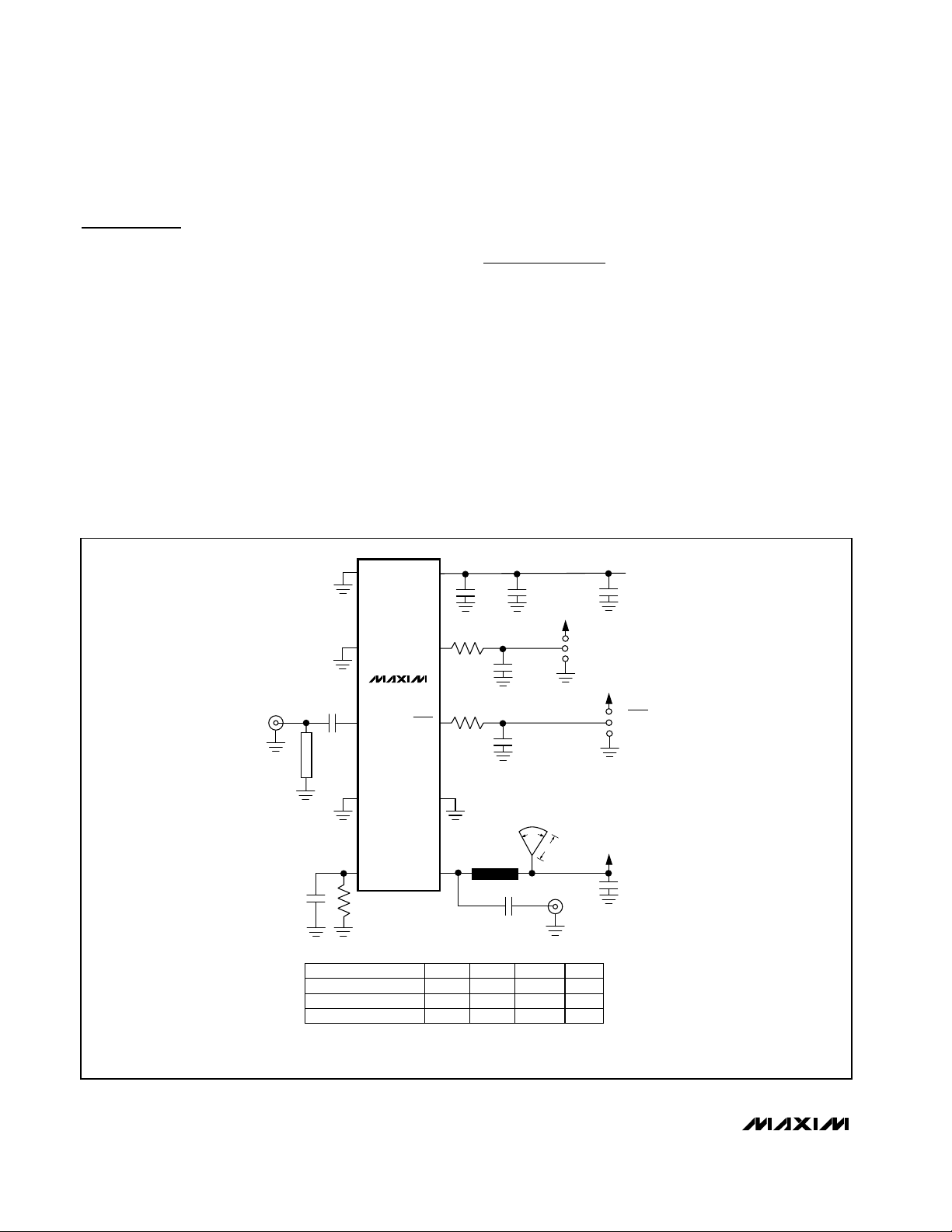
Figure 1. MAX2645 EV Kit Schematic
RFIN
Z1
1
GND
2
GND
C1
MAX2645
3
RFIN
V
GAIN
SHDN
GAIN
JU1
1
0
C10
10µF
VCC
SHDN
JU2
CC
C3
47pF
R3
1k
9
C8
0.1µF
R2
1k
8
C8
0.1µF
C6
0.1µF
V
CC
1
0
4
GND
5
BIAS
C2
220pF
*BOARD MATERIAL = GETek, COPPER THICKNESS = 1 oz
BOARD THICKNESS = 0.012in, DIELECTRIC CONSTANT = 3.8
R1
APPLICATION CIRCUIT
LNA, LOW NF
LNA, HIGH INPUT IP3
PA PREDRIVER
GND
RFOUT
1000pF
0.01µF
7
T
L
EQUIV
8
C1
1.5pFZ11.8nH
0.75pF
0.75pF
RADIAL STUB*
LINE
= 1.5nH
C4
0.75pF
R
40°
BIAS
294mils
(kΩ)
20
20
15
RFOUT
V
CC
3.3
3.3
5.0
VCC
C9
1000pF
(V)
Page 3

Evaluates: MAX2645
MAX2645 Evaluation Kit
_______________________________________________________________________________________ 3
meter to measure the actual power at the end of the
SMA connector. Turn the output of the signal generator off once the output power has been set.
Connect the other end of the SMA cable to the
RFIN port of the MAX2645 EV kit.
3) Spectrum Analyzer: Connect the spectrum analyz-
er to the RFOUT port of the MAX2645 EV kit using a
50Ω SMA cable. Set the center frequency of the
spectrum analyzer to 3.55GHz, the frequency span
to 1MHz, and the reference level to 0dBm. To
improve measurement accuracy, calibrate out any
cable losses and spectrum analyzer offsets.
4) Jumper Connections: To enable the MAX2645,
connect the SHDN jumper (JU2) on the EV kit to the
“1” position (SHDN = V
CC
). To place the MAX2645
in high-gain mode, connect the GAIN jumper (JU1)
on the EV kit to the “1” position (GAIN = VCC).
Analysis
Turn on the power supply, then the RF signal generator. The ammeter should read approximately 9.2mA,
and the spectrum analyzer should show an output
power of approximately -6dBm in high-gain mode. Be
sure to take into account cable and board losses when
calculating power gain. Typical board losses are 0.5dB
at 3.5GHz.
To evaluate the MAX2645 in low-gain mode, connect
the GAIN jumper (JU1) on the EV kit to the “0” position
(GAIN = GND). The ammeter should read approximately 3mA, and the spectrum analyzer should show an output power of approximately -31dBm in low-gain mode.
To evaluate the MAX2645 low-power shutdown mode,
connect the SHDN jumper (JU2) on the EV kit to the “0”
position (SHDN = GND). The ammeter should read
approximately 0.1µA.
To evaluate the MAX2645 as a low-noise amplifier with
higher linearity performance or as a PA predriver,
replace capacitor C1, Z1, and resistor R1 with the components recommended in the EV kit schematic (Figure
1). Refer to the MAX2645 data sheet for applicationspecific performance data.
Layout and Bypassing
The MAX2645 RFOUT output port requires an equivalent 1.5nH of high-impedance transmission line to V
CC
for proper biasing and matching. This transmission line
is terminated at the VCC node with a radial stub for
high-frequency bypassing. This arrangement provides
a high-Q, low-loss bias network used to optimize performance. The radial stub can be replaced with an
appropriate microwave capacitor.
Good PC board layout is an essential aspect of RF circuit design. The MAX2645 EV board can serve as a
guide for layout of your board. Keep PC board trace
lengths as short as possible to minimize parasitics and
losses. Keep bypass capacitors as close to the device
as possible with low-inductance connections to the
ground plane. Refer to the MAX2645 data sheet for
more information regarding bypassing.
Figure 2. MAX2645 EV Kit PC Board Layout—Component
Placement Guide
Figure 3. MAX2645 EV Kit PC Board Layout—Component Side
1.0"
1.0"
Page 4

Maxim cannot assume responsibility for use of any circuitry other than circuitry entirely embodied in a Maxim product. No circuit patent licenses are
implied. Maxim reserves the right to change the circuitry and specifications without notice at any time.
4 _____________________Maxim Integrated Products, 120 San Gabriel Drive, Sunnyvale, CA 94086 408-737-7600
© 2000 Maxim Integrated Products Printed USA is a registered trademark of Maxim Integrated Products.
Evaluates: MAX2645
MAX2645 Evaluation Kit
Figure 4. MAX2645 EV Kit PC Board Layout—Ground Plane
Figure 5. MAX2645 EV Kit PC Board Layout—Power Plane
Figure 6. MAX2645 EV Kit PC Board Layout—Solder Side
1.0"
1.0"
1.0"
 Loading...