


General Description
The MAX2371/MAX2373 wideband low-noise amplifier
(LNA) ICs are designed for direct conversion receiver
(DCR) or very low intermediate frequency (VLIF) receiver
applications. They contain single-channel, single-ended
LNAs with switchable attenuator and automatic gain control (AGC) intended as a low-noise gain stage. These
devices provide high gain-control range (typically 60dB)
at radio frequency (RF) with excellent noise and reverse
isolation characteristics.
The MAX2371/MAX2373 can work over the frequency
range from 100MHz to 1GHz. In practice, only a narrow
band is needed in each application, so different matching
circuits can be applied. The devices are dynamically configured through the digital/analog control pins to select
either maximum gain and low noise figure or power-saving
mode. In addition, the MAX2371/MAX2373 feature
high/low-current modes, high/low attenuation modes, linearly controlled gain states, and shutdown mode.
Applications
Direct Conversion Receiver (DCR)
Very Low IF Receiver
Features
♦ Low Noise Figure (1.8dB typical)
♦ High Small-Signal Gain (15dB Nominal)
♦ Wide Frequency Range of Operation
(100MHz to 1GHz)
♦ 20dB Step Attenuator
♦ 45dB AGC Range Excluding Step Attenuator
♦ 2.65V to 3.3V Single-Supply Operation
♦ Shutdown Mode
♦ 3.5mA Supply Current, Adjustable Down to 2.5mA
♦ 40dB Reverse Isolation
MAX2371/MAX2373
LNAs with Step Attenuator and VGA
________________________________________________________________ Maxim Integrated Products 1
Ordering Information
19-2301; Rev 1; 10/06
For pricing, delivery, and ordering information, please contact Maxim/Dallas Direct! at
1-888-629-4642, or visit Maxim’s website at www.maxim-ic.com.
EVALUATION KIT
AVAILABLE
PART
TEMP RANGE
PINPACKAGE
PKG
CODE
MAX2371EGC
12 QFN-EP*
G1233-1
MAX2371ETC
T1233-3
MAX2371ETC+
T1233+3
MAX2373EGC
12 QFN-EP*
G1233-1
MAX2373ETC
T1233-3
MAX2373ETC+
T1233+3
TOP VIEW
12
GND11RF_V
CC
10
RSET
45
AGC6LNA_I
1
2LNA_E
3
9
8
7RX_EN
AGC_BYP
LNA_V
CC
LNA_OUT
MAX2371
MAX2373
LNA_IN
RF_ATTN
QFN/TQFN
Pin Configuration
AGC
RF_V
CC
GND
LNA_OUT
LNA_IN
AGC_BYP
EXPONENTIAL
CONVERTER
AGC
AMP
LNA
RF_ATTN
RF
ATTENUATOR
LNA_V
CC
LNA_I
RX_EN
LNA_E
RSET
MAX2371
MAX2373
Functional Diagram
*EP = Exposed pad.
+Denotes lead-free package.
-40°C to +85°C
-40°C to +85°C 12 TQFN-EP*
-40°C to +85°C 12 TQFN-EP*
-40°C to +85°C
-40°C to +85°C 12 TQFN-EP*
-40°C to +85°C 12 TQFN-EP*
MAX2371/MAX2373
LNAs with Step Attenuator and VGA
2 _______________________________________________________________________________________
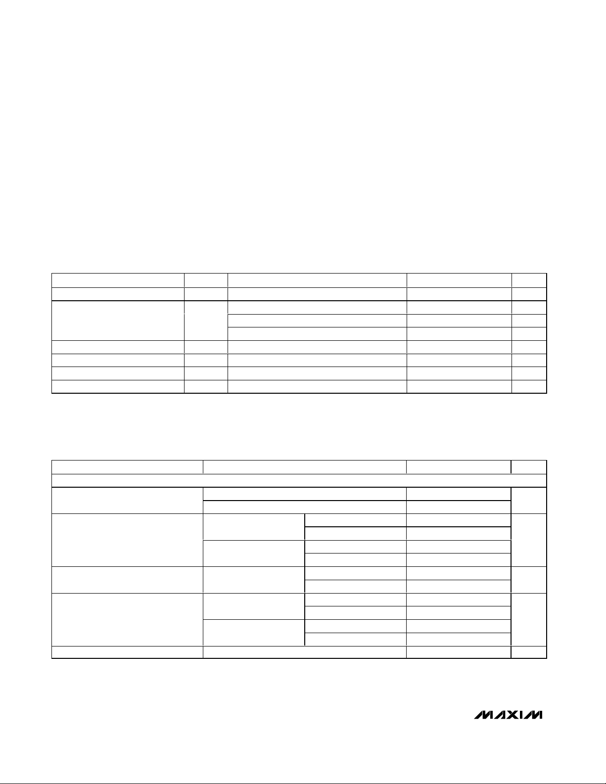
ABSOLUTE MAXIMUM RATINGS
DC ELECTRICAL CHARACTERISTICS
(VCC= 2.775V, RX_EN = high, R
SET
= 1.1kΩ, V
AGC
= VCC/2, TA= -40°C to +85°C. Typical values are at TA= +25°C, unless other-
wise noted.)
Stresses beyond those listed under “Absolute Maximum Ratings” may cause permanent damage to the device. These are stress ratings only, and functional
operation of the device at these or any other conditions beyond those indicated in the operational sections of the specifications is not implied. Exposure to
absolute maximum rating conditions for extended periods may affect device reliability.
VCCto GND...........................................................-0.3V to +3.6V
All Pins Excluding Grounds to Pin GND.....-0.3V to (V
CC
+ 0.3V)
LNA Input Power (RX_EN = low) ........................................5dBm
Continuous Power Dissipation (T
A
= +70°C)
12-Pin QFN (derate 11.9mW/°C above +70°C) ...........952mW
Operating Temperature Range ...........................-40°C to +85°C
Junction Temperature......................................................+150°C
Storage Temperature Range .............................-65°C to +160°C
Soldering Temperature (10s) ...........................................+300°C
PARAMETER
CONDITIONS
UNITS
Supply Voltage V
CC
V
RX_EN = low, VCC = 3.3V 0.5 20 µA
LNA_I = high, RF_ATTN = low 3.5 5.5 mASupply Current I
CC
LNA_I = low 2.5 3.5 mA
Digital Input Logic High V
IH
Pins LNA_I, RF_ATTN, RX_EN 0.7 ✕ V
CC
V
Digital Input Logic Low V
IL
Pins LNA_I, RF_ATTN, RX_EN 0
V
Logic Pin Impedance Logic pins RX_EN, RF_ATTN, LNA_I 50 kΩ
AGC Pin Impedance Pins AGC
kΩ
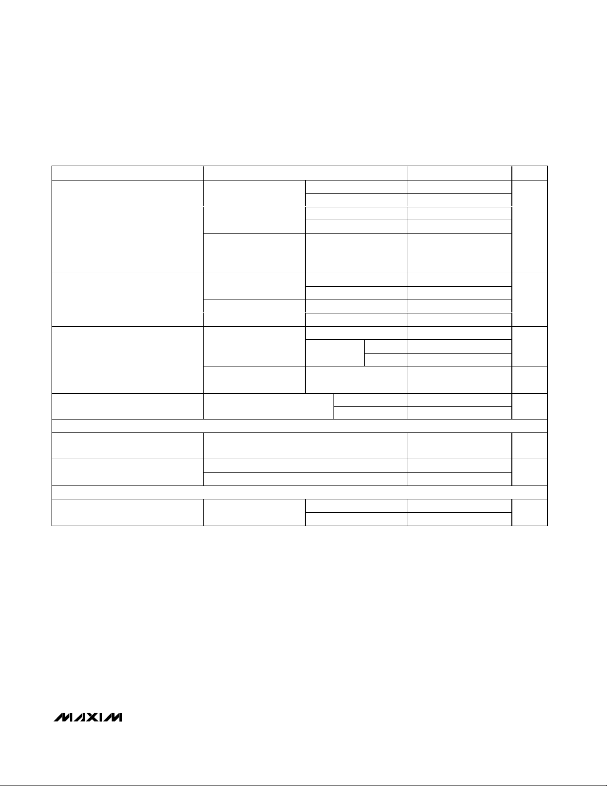
AC ELECTRICAL CHARACTERISTICS
(MAX2371/MAX2373 EV Kits, VCC= 2.65V to 3.3V, RX_EN = high, R
SET
= 1.1kΩ, TA= -40°C to +85°C. Typical values are at VCC=
2.775V; for MAX2371 f
RF
= 150MHz, for MAX2373 fRF= 850MHz to 940MHz; TA= +25°C, unless otherwise noted.) (Note 1)
PARAMETER CONDITIONS
UNITS
LNA AND AGC AMP CHARACTERISTICS
Low band (MAX2371)
Radio Frequency Range (Note 2)
High band (MAX2373)
MHz
MAX2371 -12
LNA_I = high;
RF_ATTN = low
MAX2373 -15
MAX2371 -14 -10
Input Return Loss (S11)
(Note 3)
LNA_I = high;
RF_ATTN = high
MAX2373 -10
dB
MAX2371 -40 -35
Reverse Isolation (S12) Over AGC range
MAX2373 -42 -35
dB
MAX2371 13
16
LNA_I = high, TA =
+25°C, V
CC
= 2.775V
MAX2373 14
17
MAX2371
12
Max Power Gain (Note 3)
LNA_I = low, T
A
=
+25°C, V
CC
= 2.775V
MAX2373
13
dB
Gain Variation Over Temperature TA = -40°C to +85°C, V
AGC
< 1.8V
2.0 dB
SYMBOL
MIN TYP MAX
2.65 2.775 3.30
0.3 ✕ V
100
MIN TYP MAX
136 150 174
850 900 940
14.5
15.5
10.5
10.5
-2.0
V
CC
CC
-9.5
-9.5
-6.5
MAX2371/MAX2373
LNAs with Step Attenuator and VGA
_______________________________________________________________________________________ 3
AC ELECTRICAL CHARACTERISTICS (continued)
(MAX2371/MAX2373 EV Kits, VCC= 2.65V to 3.3V, RX_EN = high, R
SET
= 1.1kΩ, TA= -40°C to +85°C. Typical values are at VCC=
2.775V; for MAX2371 f
RF
= 150MHz, for MAX2373 fRF= 850MHz to 940MHz; TA= +25°C, unless otherwise noted.) (Note 1)
PARAMETER CONDITIONS
UNITS
V
AGC
= 1.275V 1.8 2.2
V
AGC
= 1.575V 5.0 7.7
V
AGC
= 1.875V 11
LNA_I = high, TA =
+25°C, V
CC
= 2.775V,
RF_ATTN = low
V
AGC
= 2.175V 20
SSB Noise Figure vs. AGC
LNA_I = low, T
A
=
+25°C, V
CC
= 2.775V,
RF_ATTN = low
V
AGC
= 1.275V 2.1 2.6
dB
LNA_I = high
RF_ATTN = low,
V
AGC
< 1.8V
LNA_I = low -24 -22
LNA_I = high -3 0
Input 1dB Compression Point
RF_ATTN = high,
V
AGC
< 1.8V
LNA_I = low -9
dBm
LNA_I = high -5 -1
-7 -4
RF_ATTN = low,
V
AGC
= VCC/2
-12 -9
dBm
Input IP3 (Notes 4, 5)
RF_ATTN = high,
LNA_I = high 9 13
dBm
MAX2371
-8
Input IP3 Over AGC Range
RF_ATTN = low, LNA_I = high,
V
AGC
= V
CC
/2 to 1.80V
MAX2373
dBm
AGC RESPONSE
AGC Attenuation Range (Note 6)
V
CC
= 2.775V, RF_ATTN = low, V
AGC
= 1.3375V
to 2.575V, T
A
= +25°C
35 45 dB
RF_ATTN = low, V
AGC
= 1.625V 32 40 47
AGC Slope Over Control Range
RF_ATTN = high, V
AGC
= 1.625V 24 33 41
dB/V
RF STEP ATTENUATOR
MAX2371
Gain Step
RF_ATTN = high to low,
LNA_I = high
MAX2373
dB
Note 1: Parameters over temperature and supply voltage range are guaranteed by design and characterization, unless otherwise noted.
Note 2: Operation outside these frequency bands is possible but has not been characterized. See Typical Operating Characteristics.
Note 3: Measured with external matching network.
Note 4: f
IN1
= 150MHz, f
IN2
= 150.1MHz, PIN= -30dBm for both tones (MAX2371).
Note 5: f
IN1
= 900MHz, f
IN2
= 900.1MHz, PIN= -30dBm for both tones (MAX2373).
Note 6: Parameters are guaranteed by production test.
V
AGC
= V
/2 to 2.575V
CC
LNA_I = low
MIN TYP MAX
14.5
-21.5 19.5
-6.5
MAX2371
MAX2373
-10.5
-12.5 -10.5
16.0 17.5 19.0
18.0 19.5 21.0
MAX2371/MAX2373
LNAs with Step Attenuator and VGA
4 _______________________________________________________________________________________
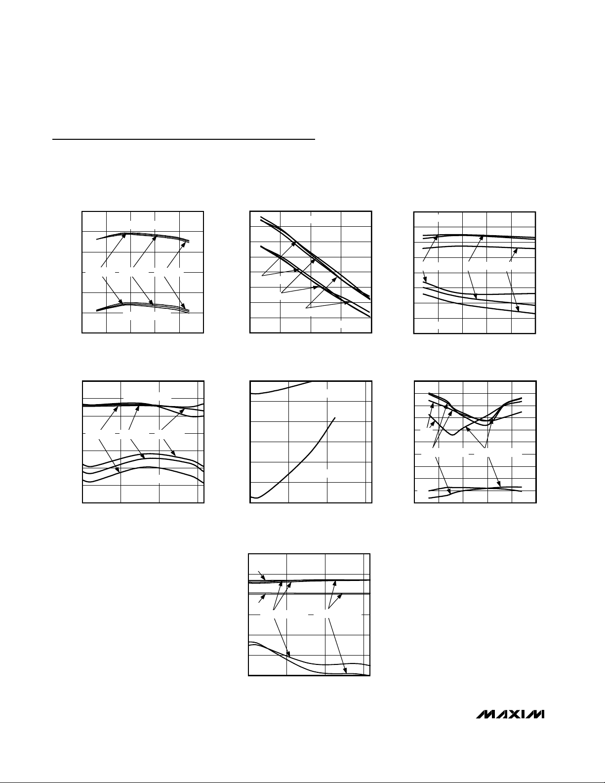
Typical Operating Characteristics
(MAX2371/MAX2373 EV Kits, VCC= 2.775V, RX_EN = high, R
SET
= 1.1kΩ, LNA_I = high, TA= +25°C. For MAX2371, fRF= 150MHz;
for MAX2373, fRF= 900MHz, unless otherwise noted.)
GAIN vs. FREQUENCY
MAX2371 toc01
FREQUENCY (MHz)
GAIN (dB)
170160150140
-5
0
5
10
15
20
-10
130 180
TA = +85°C
TA = -40°C
TA = +25°C
RF_ATTN = LOW
RF_ATTN = HIGH
GAIN vs. V
AGC
MAX2371 toc02
V
AGC
(V)
GAIN (dB)
2.42.01.6
-50
-40
-30
-20
-10
0
10
20
-60
1.2 2.8
RF_ATTN = LOW
RF_ATTN = HIGH
TA = +85°C
TA = +25°C
TA = -40°C
IIP3 vs. V
AGC
MAX2371 toc03
V
AGC
(V)
IIP3 (dBm)
1.71.61.4 1.5
-10
-5
0
5
10
15
20
25
-15
1.3 1.8
RF_ATTN = LOW
RF_ATTN = HIGH
TA = +85°C
TA = +25°C
TA = -40°C
P
1dB
vs. V
AGC
MAX2371 toc04
V
AGC
(V)
P
1dB
(dBm)
2.72.21.7
-20.0
-15.0
-10.0
-5.0
0
5.0
10.0
-25.0
1.2
TA = +25°C
RF_ATTN = LOW
RF_ATTN = HIGH
TA = +85°C
TA = -40°C
NOISE FIGURE vs. V
AGC
MAX2371 toc05
V
AGC
(V)
NOSIE FIGURE (dB)
2.72.21.7
5
10
15
20
25
30
0
1.2
RF_ATTN = LOW
RF_ATTN = HIGH
S11, S22, S12 vs. FREQUENCY
MAX2371 toc06
FREQUENCY (MHz)
S11, S22, S12 (dB)
170160150140
-45
-40
-35
-30
-25
-20
-15
-10
-5
0
-50
130 180
S22
S11
S12
RF_ATTN = LOW RF_ATTN = HIGH
S11, S22, S12 vs. V
AGC
MAX2371 toc07
V
AGC
(V)
S11, S22, S12 (dB)
2.72.21.7
-50
-40
-30
-20
-10
0
-60
1.2
S22
S11
S11
S12
RF_ATTN = HIGH
RF_ATTN = LOW
MAX2371

MAX2371/MAX2373
LNAs with Step Attenuator and VGA
_______________________________________________________________________________________ 5
IIP3 vs. V
AGC
MAX2371 toc10
V
AGC
(V)
IIP3 (dBm)
1.71.61.51.4
-10
-5
0
5
10
15
20
-15
1.3 1.8
RF_ATTN = LOW
RF_ATTN = HIGH
TA = -40°C
TA = +25°C
TA = +85°C
P
1dB
vs. V
AGC
MAX2371 toc11
V
AGC
(V)
P
1dB
(dBm)
2.72.21.7
-20.0
-15.0
-10.0
-5.0
0
5.0
10.0
-25.0
1.2
TA = -40°C
TA = 85°C
TA = +25°C
RF_ATTN = LOW
RF_ATTN = HIGH
NOISE FIGURE vs. V
AGC
MAX2371 toc12
V
AGC
(V)
NOSIE FIGURE (dB)
2.72.21.7
5
10
15
20
25
30
0
1.2
RF_ATTN = LOW
RF_ATTN = HIGH
Typical Operating Characteristics (continued)
(MAX2371/MAX2373 EV Kits, VCC= 2.775V, RX_EN = high, R
SET
= 1.1kΩ, LNA_I = high, TA= +25°C. For MAX2371, fRF= 150MHz;
for MAX2373, fRF= 900MHz, unless otherwise noted.)
S11, S22, S12 vs. FREQUENCY
MAX2371 toc13
FREQUENCY (MHz)
S11, S22, S12 (dB)
920900880860
-45
-40
-35
-30
-25
-20
-15
-10
-5
0
-50
840 940
S22
S11
S12
S11
RF_ATTN = LOW RF_ATTN = HIGH
S11, S22, S12 vs. V
AGC
MAX2371 toc14
V
AGC
(V)
S11, S22, S12 (dB)
2.72.21.7
-35
-40
-30
-25
-20
-15
-10
-5
0
-50
-45
1.2
S22
S11
S11
S12
RF_ATTN = HIGH
RF_ATTN = LOW
GAIN vs. FREQUENCY
MAX2371 toc08
FREQUENCY (MHz)
GAIN (dB)
920900880860
-5
0
5
10
15
20
-10
840 940
TA = +85°C
TA = -40°C
TA = +25°C
RF_ATTN = LOW
RF_ATTN = HIGH
GAIN vs. V
AGC
MAX2371 toc09
V
AGC
(V)
GAIN (dB)
2.42.01.6
-40
-30
-20
-10
0
10
20
-50
1.2 2.8
RF_ATTN = LOW
RF_ATTN = HIGH
TA = -40°C
TA = +25°C
TA = +85°C
MAX2373

MAX2371/MAX2373
LNAs with Step Attenuator and VGA
6 _______________________________________________________________________________________
Table 1. MAX2371 S-Parameters
(VCC= 2.775V, RX_EN = high, LNA_I = high, RF_ATTN = low, PIN= -30dBm, TA= +25°C.)
LNA (S11) LNA (S21) LNA (S12) LNA (S22)
FREQUENCY
(MHz)
PHASE
PHASE
PHASE
PHASE
10
-4.8477
0.002136 -102.490
-1.1632
100
-29.9420
0.002021 61.149
-4.4481
150
-35.6990
89.6950 0.003089 138.790
-6.0754
200
-43.4190
75.0130 0.003238 47.793
-7.7399
300
-55.1180
58.1420 0.004439 83.493
-11.1180
400
-65.2420
0.003346 82.612
-14.6680
500
-73.5040
36.0670 0.004395 68.614
-18.0970
600
-80.6450
28.4990 0.006155 71.599
-21.2670
700
-85.6220
22.7470 0.004143 56.224
-23.5710
800
-89.2240
18.1080 0.005580 93.741
-25.5640
900
-91.6690
14.3230 0.005309 89.871
-27.8980
1000
-94.0260
9.9632 0.007592 99.418
-30.2110
1100
-96.1830
5.9889 0.008451 122.090
-32.2310
1200
-98.0560
1.1604 0.011955 129.220
-34.6290
1300
-4.3698 0.014966 130.200
-37.6190
1400
-10.2610 0.019602 131.440
-40.1400
1500
-16.1910 0.023963 128.730
-42.0800
1600
-23.1040 0.031521 121.710
-43.7830
1700
-29.9130 0.039505 114.740
-45.2980
1800
-37.6360 0.047321 109.530
-46.5300
1900
-45.7240 0.056859 100.480
-48.7600
2000
-53.5490 0.063929 92.788
-50.8360
MAGNITUDE
0.943409
0.746965
0.728794
0.705066
0.704636
0.719615
0.731998
0.736258
0.738074
0.738465
0.736843
0.720668
0.712090
0.690343
0.657098 -100.3900 0.861113
0.606583 -103.2500 0.891302
0.545500 -106.6300 0.925092
0.469143 -111.0400 0.966707
0.372315 -116.0200 1.002767
0.267147 -123.3900 1.021504
0.150522 -137.6100 1.021081
0.060478 160.4700 0.995004
MAGNITUDE
5.980672 171.1200
2.959750 102.1900
2.347308
1.769355
1.290313
1.060230 45.42700
0.930754
0.849660
0.810047
0.796627
0.793643
0.801946
0.816554
0.836893
MAGNITUDE
MAGNITUDE
0.998803
0.994752
0.985485
0.986870
0.979073
0.963130
0.947862
0.935998
0.930518
0.935158
0.933372
0.941369
0.940860
0.936774
0.930219
0.925103
0.926670
0.939042
0.949456
0.966296
0.975001
0.971740

MAX2371/MAX2373
LNAs with Step Attenuator and VGA
_______________________________________________________________________________________ 7
Table 2. MAX2373 S-Parameters
(VCC= 2.775V, RX_EN = high, LNA_I = high, RF_ATTN = low, PIN= -30dBm, TA= +25°C.)
LNA (S11) LNA (S21) LNA (S12) LNA (S22)
FREQUENCY
(MHz)
PHASE
PHASE
PHASE
PHASE
10
-0.8171
-178.830 0.002162 -89.276
-0.8184
100
-9.1461
163.940 0.001346 78.684
-2.3140
200
-16.6570
150.770 0.002137 32.634
-3.8136
300
-22.6500
139.770 0.002217 72.860
-5.6360
400
-27.4800
130.020 0.001332 86.532
-7.2455
500
-30.9910
121.750 0.001641 86.431
-8.9841
600
-34.5840
113.750 0.002297 70.617
-10.7250
700
-37.2530
107.480 0.001701 105.050
-12.1890
800
-39.7830
101.820 0.002688 73.619
-13.4650
900
-41.8580
97.239 0.001077 143.410
-15.1090
1000
-42.9140
92.435 0.001617 102.100
-16.8900
1100
-44.4030
87.484 0.001442 151.320
-18.5160
1200
-45.9560
82.687 0.002973 178.790
-20.8080
1300
-47.1900
78.482 0.003764 -175.540
-23.6930
1400
-47.9420
74.093 0.004195 -176.470
-25.7200
1500
-49.1020
70.061 0.007366 -163.150
-27.9410
1600
-50.1550
66.443 0.008200 -162.620
-29.8050
1700
-51.3530
63.336 0.010929 -163.870
-32.1340
1800
-52.9500
59.870 0.015327 -160.350
-33.9510
1900
-54.6510
56.385 0.016692 -162.560
-36.3470
2000
-55.6650
53.411 0.018843 -177.660
-38.8240
Table 3. MAX2371 Typical Noise Parameters
(VCC= 2.775V, RX_EN = high, LNA_I = high, RF_ATTN = low, PIN= -30dBm, TA= +25°C, data from design simulation.)
FREQUENCY (MHz) NF
MIN
(dB) ⎜Γ
OPT
⎟∠ Γ
OPT
RN (Ω)
130 0.84 0.34 46.4 8.8
140 0.83 0.35 49.3 8.5
150 0.82 0.34 52.7 8.1
160 0.81 0.34 56.2 7.8
170 0.81 0.33 59.8 7.5
180 0.81 0.32 63.4 7.1
MAGNITUDE
0.952248
0.933405
0.884179
0.824784
0.767609
0.709643
0.656682
0.616673
0.586388
0.558837
0.536056
0.524439
0.516220
0.511487
0.508259
0.504028
0.509736
0.510000
0.513009
0.515994
0.510141
MAGNITUDE
7.273610
7.077013
6.529802
5.929253
5.400078
4.904559
4.431492
4.016983
3.644182
3.313218
3.059039
2.805078
2.614027
2.417436
2.253642
2.090210
1.975627
1.841259
1.719293
1.597405
1.467185
MAGNITUDE
MAGNITUDE
1.000092
0.993482
0.991791
0.983762
0.971102
0.958562
0.955972
0.946259
0.941846
0.933168
0.938912
0.932492
0.926200
0.919094
0.919952
0.917498
0.919486
0.923092
0.924634
0.933781
0.933039

MAX2371/MAX2373
LNAs with Step Attenuator and VGA
8 _______________________________________________________________________________________
Detailed Description
The MAX2371/MAX2373 are single-channel, singleended, low-noise amplifiers with two gain modes and
continuous automatic gain control (AGC) in both
modes. The devices are intended as low-noise gain
stages for direct conversion receivers (DCR) or very
low IF (VLIF) receivers. These devices provide high
gain-control dynamic range (typ 60dB) at RF with
excellent noise and reverse isolation characteristics.
Vary the resistor at pin RSET and the inductor at LNA_E
to meet a wide range of gain and linearity requirements. The ICs can be dynamically configured through
pins LNA_I and RF_ATTN. When LNA_I is connected to
VCC, the LNA is in high-current mode, nominally configured for maximum gain and low noise figure of the
amplifier. If the LNA_I pin is grounded, the current of
the LNA is reduced, and the associated gain, input IP3,
and noise figure are degraded. The devices have two
gain modes configured by the RF_ATTN pin. Set
RF_ATTN high for low-gain mode; set RF_ATTN low for
high-gain mode. The gain step between these two gain
modes typically is 20dB.
Table 4. MAX2373 Typical Noise Parameters
(VCC= 2.775V, RX_EN = high, LNA_I = high, RF_ATTN = low, PIN= -30dBm, TA= +25°C, data from design simulation.)
FREQUENCY (MHz) NF
MIN
(dB) ⎜Γ
OPT
⎟∠ Γ
OPT
RN (Ω)
850 1.06 0.35 60.5 10.02
870 1.08 0.35 61.8 9.98
890 1.10 0.34 63.3 9.94
910 1.11 0.34 64.7 9.90
930 1.13 0.33 66.2 9.86
950 1.15 0.33 67.7 9.82
Pin Description
PIN NAME FUNCTION
1 LNA_IN RF Input. Requires DC-blocking capacitor and external matching network.
2 LNA_E LNA Emitter. Connect to GND with an inductor. See inductor value in Table 5.
3 RX_EN LNA Control. Set RX_EN high to enable LNA; set RX_EN low to disable LNA.
4
Attenuator Control. Set RF_ATTN high for low-gain mode; set RF_ATTN low for high-gain mode.
5 AGC
AGC Input Voltage. Set AGC to V
CC
/2 for maximum gain. Set AGC to V
CC
- 200mV for minimum gain. If
left unconnected, the LNA will operate at maximum gain and optimum noise figure.
6 LNA_I
LNA Nominal Bias-Current Setting. Set LNA_I high for high-current mode. Set LNA_I low for low-current
mode. If left unconnected, the default state of the LNA is high-current mode.
7
RF Output Pin. Requires a pullup inductor to LNA_VCC and external matching network.
8
Supply Voltage for the AGC Amplifier
9
AGC Bypass. Connect a capacitor to ground. The value of the capacitor is a compromise of AGC
response time and blocker frequency offset.
10 RSET
External pin for precision resistor to ground to set reference bias current for IC; typical bias current is
50µA to 100µA.
11 RF_V
CC
Supply Voltage for the LNA. Bypass with a capacitor to GND as close to the pin as possible. Do NOT
connect any tuned circuits to this supply pin.
12 GND Ground
EP
Exposed
Pad
Internally connected to GND. Connect to a large ground plane to maximize thermal performance.
Do not use as the sole ground connection point.
Table 5. Inductor Selection
RF_ATTN
LNA_OUT
LNA_V
CC
AGC_BYP
BAND
150MHz (VHF) 33 Low Band
450MHz (UHF) 10 Low Band
450MHz (UHF) 2.7 High Band
800MHz 2.5 High Band
1GHz 1.8 High Band
L SERIES VALUE
(nH)
LNA TYPE

MAX2371/MAX2373
LNAs with Step Attenuator and VGA
_______________________________________________________________________________________ 9
The MAX2371/MAX2373 can be turned off in transmit or
battery-save standby mode. The receive-enable pin
(RX_EN) also can turn off the devices even if VCCis not
removed, because multiple LNAs can be connected to
the same VCCfor multiband applications.
The devices allow external matching networks to configure
operation in a wide frequency range. Refer to the EV kit
schematic for a guide to designing the matching network.
Applications Information
AGC
The AGC of the MAX2371/MAX2373 is controlled by an
external voltage at pin AGC. The amplifier is at full gain
if the voltage at pin AGC is nominally VCC/2. It is at minimum gain if the voltage at pin AGC is VCC. The AGC
attenuation range, which is continuously variable, is
specified at 45dB. The IP3 will degrade slightly as AGC
reduces the gain.
The devices include two gain modes. Set RF_ATTN high
to enable the low-gain mode, which reduces the gain by
about 20dB. Low-gain mode will increase the system IP3
by approximately 18dB, which provides strong signal
overload and IM protection. An external pin (RF_ATTN)
controls switching between gain modes so this function
can be combined with overall AGC control. AGC is independent of the choice of gain mode. The gain step
between modes is in addition to the range of AGC, allowing a large overall gain-control range.
AGC Response
A linear transfer function between the AGC control signal
and the AGC attenuation is realized in dB. The linear
relationship in dB/V is maintained to ±10% over a specified attenuation range. Any compensation for gain-mode
change must come from the AGC control. After reducing
gain by switching the RF_ATTN pin, reduce the AGC
voltage to achieve the desired overall gain.
The LNA current also can be changed by toggling the
LNA_I pin. This operation is independent of gain mode
and AGC control. The low-current mode is intended as a
second (reduced-current) quiescent point of operation
for strong-signal operating environments.
Matching Networks
For best performance, match LNA_IN and LNA_OUT to
50Ω for the band of operation. Typical matching circuits
for two bands (136MHz to 174MHz and 850MHz to
940MHz) are shown in the EV kit. The chip impedance
changes minimally from low to high gain and with AGC.
The input requires a DC-blocking capacitor. The size of
this capacitor influences the startup time and IP3. There
is a trade-off between these: A large DC-blocking
capacitor means a good IP3 and slow startup. The maximum startup time is determined by the equation below:
MAXT
START
= 40 ✕ C
AC
✕ R
SET
,
where CAC= AC-coupling cap in Farads, R
SET
= current-
setting resistor in Ω.
IP3 will improve with the separation of the interfering
tones, so a wider channel system can use a smaller DCblocking capacitor and achieve a better IP3. The customer also can change the emitter inductor at LNA_E to
get the desired linearity and gain. Changing this inductor value requires a change to the input match. The output is an open collector and needs a pullup inductor. A
load resistor also can be connected across it. The resistor determines the trade-off between the bandwidth of
the match and the gain. A small load resistor means a
wider match and lower gain.
Layout Issues
For best performance, pay attention to power-supply
issues as well as to the layout of the RFOUT matching
network. The EV kit can be used as a layout example.
Ground connections followed by supply bypass are the
most important.
Power-Supply Bypassing
The MAX2371/MAX2373 have two supply pins:
LNA_VCCand RF_VCC. These must be bypassed separately. It is assumed that there is a large capacitor
decoupling the power supply. LNA_VCCand RF_V
CC
are each decoupled with 1500pF (MAX2371) or 100pF
(MAX2373) capacitor. Use separate paths to the ground
plane for each of the bypass capacitors, and minimize
trace length to reduce inductance. The exposed pad
must be connected to system ground with very low
impedance vias.
Power-Supply Layout
To minimize coupling between sections of the IC, the
ideal power-supply layout is a star configuration with a
large decoupling capacitor at a central VCCnode. The
VCCtraces branch from this central node, each to a separate VCCnode in the PC board. At the end of each
trace is a bypass capacitor that has low ESR at the RF of
operation. This arrangement provides local decoupling
at each VCCpin. At high frequencies, any signal leaking
out of one supply pin sees a relatively high impedance
(formed by the VCCtrace inductance) to the central V
CC
node and an even higher impedance to any other supply
pin, as well as a low impedance to ground through the
bypass capacitor.
MAX2371/MAX2373
LNAs with Step Attenuator and VGA
Maxim cannot assume responsibility for use of any circuitry other than circuitry entirely embodied in a Maxim product. No circuit patent licenses are
implied. Maxim reserves the right to change the circuitry and specifications without notice at any time.
_____________________Maxim Integrated Products, 120 San Gabriel Drive, Sunnyvale, CA 94086 408-737-7600
© 2006 Maxim Integrated Products is a registered trademark of Maxim Integrated Products, Inc.
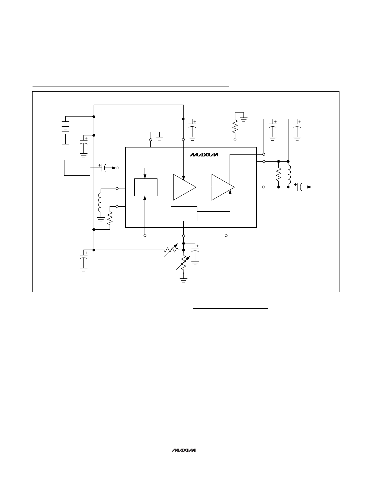
Impedance-Matching Network Layout
The input- and output-matching networks are sensitive to
layout-related parasitic inductions. To minimize parasitic
inductance, keep traces short and place components as
close as possible to the chip. To minimize parasitic
capacitance, minimize the area of the plane.
Chip Information
TRANSISTOR COUNT: 360
AGC
RF_V
CCGND
LNA_OUT
LNA_IN
2.775 V
DC
AGC_BYP
EXPONENTIAL
CONVERTER
AGC
AMP
LNA
RF_ATTN
RF
ATTENUATOR
RF
INPUT MATCH
LNA_V
CC
LNA_I
RSET
1.1kΩ
PRECISION
RX_EN
LNA_E
MAX2371
MAX2373
Typical Operating Circuits
Revision History
Pages changed at Rev 1: 1, 8, 10
 Loading...