

Page 1
General Description
The MAX2264/MAX2265/MAX2266 evaluation kits (EV
kits) simplify evaluation of the MAX2264/MAX2265/
MAX2266 power amplifiers (PAs), which are designed for
operation in IS-98-based CDMA, IS-136-based TDMA,
and PDC cellular phones operating in the 900MHz range.
The kits enable testing of the devices’ RF performance
and require no additional support circuitry. The EV kits’
signal inputs and outputs use SMA connectors to facilitate the connection of RF test equipment.
Each kit is assembled with either the MAX2264, MAX2265
or MAX2266 and incorporates input and output matching
components optimized for the 824MHz to 849MHz RF frequency band. These EV kits are capable of operating at
RF frequencies from 750MHz to 1000MHz with the appropriate matching components.
Features
♦ Easy Evaluation of MAX2264/MAX2265/MAX2266
♦ +2.7V to +5V Single-Supply Operation
♦ RF Input/Output Matched for 824MHz to 849MHz
Operation
♦ All Matching Components Included
Evaluate: MAX2264/MAX2265/MAX2266
MAX2264/MAX2265/MAX2266 Evaluation Kits
________________________________________________________________ Maxim Integrated Products 1
19-1524; Rev 2; 11/99
PART
MAX2264EVKIT
MAX2265EVKIT
-40°C to +85°C
-40°C to +85°C
TEMP. RANGE IC PACKAGE
16 TSSOP-EP*
16 TSSOP-EP*
For free samples & the latest literature: http://www.maxim-ic.com, or phone 1-800-998-8800.
For small orders, phone 1-800-835-8769.
Ordering Information
0Ω resistor (0805)1Q1
1.2nH ±0.3nH inductor (0603)
Murata LQG11A1N2S00
1L5
39nH ±5% inductor (0603)
Murata LQG11A39NJ00
1L4
12nH ±5% inductor (0603)
Murata LQG11A12NJ00
1L3
5.6nH ±2% inductor
Coilcraft 1606-6G
1L2
3.9nH ±0.3nH inductor (0603)
Murata LQG11A3N9S00
1L1
3-pin headers2JU1, JU2
SMA connectors (PC edge mount)
EF Johnson 142-0701-801
2IN, OUT
Test points 2GND, V
CC
470pF ±5% ceramic capacitor (0603)
Murata GRM39COHG471J50
1C26
51kΩ ±5% resistors (0603) 2R1, R3
MAX2264/5/6 EV kits data sheet1None
MAX2264/5/6 data sheet1None
MAX226X PC board1None
Shunts (JU1, JU2)2 None
MAX2264EUE (16-pin TSSOP-EP)1U1
DESIGNATION
0Ω resistors (0603) 3R8, R9, R10
33.2kΩ ±1% resistor (0603) 1R7
24.3kΩ ±1% resistor (0603) 1R5
DESCRIPTIONQTY
7.5kΩ ±1% resistor (0603) 1R4
30.1kΩ ±1% resistor (0603)1R2
0.01µF ±5% ceramic capacitor (0603)
Murata GRM39X7R103J50
1C20
Not installed0C15
4.7pF ±0.1pF ceramic capacitor (0402)
Murata GRM39COG4R7B50V
1C12
10pF ±0.1pF porcelain capacitor
ATC 100A100FW150X
Mounted with top side aligned six tick
marks from the zero tick mark (ruler located to the right of C11; see Figure 3)
1C11
220pF ±5% ceramic capacitor (0603)
Murata GRM39COG221J050
1C18
5.1pF ±0.1pF porcelain capacitor
ATC 100A5R1BW150X
1C10
0.01µF ±5% ceramic capacitors (0402)
Murata GRM36X7R103J16 or
Taiyo Yuden EMK105B103KW
5
C3, C5, C8,
C13, C16
DESIGNATION
100pF ±5% ceramic capacitors (0402)
Murata GRM36COG101J50 or
Taiyo Yuden UMK105CH101JW
7
C2, C4, C6,
C7, C9,
C14, C17
6.2pF ±0.25pF ceramic capacitor (0603)
Murata GRM39COG6R2C50
1C1
DESCRIPTIONQTY
10µF ±20%, 16V tantalum capacitor
AVX TAJB106M016
1C19
100pF ±5% ceramic capacitor (0603)
Murata GRM39COG101J50
1C21
*Exposed Paddle
0.1µF ±10% ceramic capacitors (0603)
Murata GRM39X7R104K50V or
Taiyo Yuden EMK107BJ104KA
4C22–C25
MAX2264 EV Kit Component List
MAX2266EVKIT
-40°C to +85°C 16 TSSOP-EP*
查询MAX2264EVKIT供应商
Page 2
Evaluate: MAX2264/MAX2265/MAX2266
MAX2264/MAX2265/MAX2266 Evaluation Kits
MAX2265 EV Kit Component List
SUPPLIER PHONE
ATC 516-622-4700
AVX 803-946-0690
Coilcraft 847-639-6400
EF Johnson 402-474-4800
Kamaya 219-489-1533
Murata Electronics 800-831-9172
Component Suppliers
FAX
516-622-4748
803-626-3123
847-639-1469
402-474-4858
219-489-2261
814-238-0490
WEB
www.atceramics.com
www.avx-corp.com
www.coilcraft.com
www.efjohnson.com
www.kamaya.com
www.murata.com
0.1µF ±10% ceramic capacitors (0603)
Murata GRM39X7R104K50V or
Taiyo Yuden EMK107BJ104KA
2C22, C23
10µF ±20%, 16V tantalum capacitor
AVX TAJB106M016
1C19
Not installed0
C12–C18,
C24, C25
9.1pF ±0.1pF porcelain capacitor
ATC 100A9R1BW150X
1C11
0.01µF ±5% ceramic capacitor (0603)
Murata GRM39X7R103J50
1C20
0.01µF ±20% high-Q ceramic capacitor
ATC 200A103MW50
1C10
0.01µF ±5% ceramic capacitors (0402)
Murata GRM36X7R103J16 or
Taiyo Yuden EMK105B103KW
3C3, C5, C8
DESIGNATION
100pF ±5% ceramic capacitors (0402)
Murata GRM36COG101J50 or
Taiyo Yuden UMK105CH101JW
5
C2, C4, C6,
C7, C9
5.1pF ±0.25pF ceramic capacitor (0603)
Murata GRM39COG5R1C050
1C1
DESCRIPTIONQTY
100pF ±5% ceramic capacitor (0603)
Murata GRM39COG101J50
1C21
Test points
Mouser 151-203
2GND, VCC
35.7kΩ ±1% resistor (0603)1R2
51kΩ ±5% resistors (0603) 2R1, R3
Not installed0Q1, R4, R5
2.2nH ±0.3nH inductor (0603)
Coilcraft 0402CS-2N2XJBG
1L6
39nH ±5% inductor (0603)
Murata LQG11A39NJ00
1L4
Not installed0L3, L5
5.6nH ±2% inductor
Coilcraft 1606-6G
1L2
5.6nH ±0.3nH inductor (0603)
Murata LQG11A5N6S00
1L1
3-pin headers2JU1, JU2
SMA connectors (PC edge mount)
EF Johnson 142-0701-801
2IN, OUT
33.2kΩ ±1% resistor (0603) 1R7
MAX2264/5/6 EV kits data sheet1None
DESIGNATION
MAX2264/5/6 data sheet1None
MAX226X PC board1None
Shunts (JU1, JU2)2 None
DESCRIPTIONQTY
MAX2265EUE (16-pin TSSOP-EP)1U1
0Ω resistors (0603)2R9, R10
ROHM 408-433-2225 408-434-0531 www.rohm.com
NEC 408-243-2111 408-243-2410 www.cel.com
470pF ±5% ceramic capacitor (0603)
Murata GRM39COG471J50
1C26
3.3pF ±5% ceramic capacitor (0402)
Murata GRM36COG220J050 or
Taiyo Yuden UMK1O5CH220JW
1C27
Taiyo Yuden 408-573-4150 408-573-4159 www.t-yuden.com
2 _______________________________________________________________________________________
Page 3
Evaluate: MAX2264/MAX2265/MAX2266
MAX2264/MAX2265/MAX2266 Evaluation Kits
_______________________________________________________________________________________ 3
0.01µF ±5% ceramic capacitor (0603)
Murata GRM39X7R103J50
1C20
Not installed0C15, C27–C30
5.1pF ±0.1pF ceramic capacitor (0402)
Murata GRM39COG5R1B50V
1C12
7.5pF ±0.1pF porcelain capacitor
ATC 100A7R5FW150X
Mounted with top side aligned six tick
marks from the zero tick mark (ruler located to the right of C11; see Figure 3)
1C11
0.1µF ±10% ceramic capacitors (0603)
Murata GRM39X7R104K50V or
Taiyo Yuden EMK107BJ104KA
4C22–C25
220pF ±5% ceramic capacitor (0603)
Murata GRM39COG221J050
1C18
3.9pF ±0.1pF porcelain capacitor
ATC 100A3R9BW150X
1C10
0.01µF ±5% ceramic capacitors (0402)
Murata GRM36X7R103J16 or
Taiyo Yuden EMK105B103KW
5
C3, C5, C8,
C13, C16
DESIGNATION
100pF ±5% ceramic capacitors (0402)
Murata GRM36COG101J50 or
Taiyo Yuden UMK105CH101JW
7
C2, C4, C6,
C7, C9,
C14, C17
6.2pF ±0.25pF ceramic capacitor (0603)
Murata GRM39COG6R2C50
1C1
DESCRIPTIONQTY
10µF ±20%, 16V tantalum capacitor
AVX TAJB106M016
1C19
100pF ±5% ceramic capacitor (0603)
Murata GRM39COG101J50
1C21
100nH ±5% inductor (0603)
Murata LQG11AR10J00
1L6
1.2nH ±0.3nH inductor (0603)
Murata LQG11A1N2S00
1L5
39nH ±5% inductor (0603)
Murata LQG11A39NJ00
1L4
4.7nH ±5% inductor (0603)
Murata LQG11A4N7J00
1L3
5.6nH ±2% inductor
Coilcraft 1606-6G
1L2
3.9nH ±0.3nH inductor (0603)
Murata LQG11A3N9S00
1L1
3-pin headers2JU1, JU2
SMA connectors (PC edge mount)
EF Johnson 142-0701-801
2IN, OUT
51kΩ ±5% resistors (0603) 2R1, R3
MAX2264/5/6 EV kits data sheet1None
MAX2264/5/6 data sheet1None
MAX226Z PC board1None
Shunts (JU1, JU2)2 None
MAX2266EUE (16-pin TSSOP-EP)1U1
DESIGNATION
0Ω resistors (0603) 3R8, R9, R10
33.2kΩ ±1% resistor (0603) 1R7
24.3kΩ ±1% resistor (0603) 1R5
DESCRIPTIONQTY
7.5kΩ ±1% resistor (0603) 1R4
26.1kΩ ±1% resistor (0603)1R2
MAX2266 EV Kit Component List
Open collector inverter
ROHM DTC143ZE
1Q2
10kΩ ±5% resistor (0603) 1R6
NEC UPG152TA1U2
510Ω ±5% resistor (0603) 1R11
470pF ±5% ceramic capacitor (0603)
Murata GRM39COHG471J50
1C26
Test points 2GND, V
CC
Page 4

Evaluate: MAX2264/MAX2265/MAX2266
MAX2264/MAX2265/MAX2266 Evaluation Kits
4 _______________________________________________________________________________________
_________________________Quick Start
The MAX2264/MAX2265/MAX2266 EV kits are fully
assembled and factory tested. Follow the instructions in
the Connections and Setup section for proper device
evaluation.
Test Equipment Required
This section lists the test equipment recommended to
verify operation of the MAX2264/MAX2265/MAX2266. It is
intended as a guide only, and some substitutions are
possible.
• An RF signal generator capable of delivering at least
+10dBm of output power at the operating frequency
with CDMA modulation (HP E4433G or equivalent)
• An RF power sensor capable of handling at least
+20dBm of output power at the operating frequency
(HP 8482A, or equivalent)
• A 20dB high-power attenuator
• An RF power meter capable of measuring up to
+20dBm of output power at the operating frequency
(HP EPM-441A or equivalent)
• An RF spectrum analyzer capable of measuring
ACPR and covering the MAX2264/MAX2265/
MAX2266’s operating frequency range (Rhodes at
Schwartz FSEA20, for example)
• A power supply capable of up to 1A at +2.7V to +5V
• A high-impedance voltmeter for measuring the actual
operating voltage
• An ammeter for measuring the supply current
(optional)
• Two 50Ω SMA cables
• A network analyzer (HP 8753D, for example) to measure small-signal return loss and gain (optional)
Connections and Setup
This section provides a step-by-step guide to operating
the EV kits and testing the devices’ functions. Do not
turn on the DC power or RF signal generator until all
connections are made.
1) Connect a 20dB high-power attenuator to the OUT
SMA connector on the EV kit. This will prevent overloading the power sensor and the power meter.
2) Connect a DC supply set to +3.3V (through an
ammeter if desired), and connect the voltmeter to
the EV kit’s VCC and GND terminals.
3) Connect an RF signal generator to the IN SMA con-
nector. Set the generator for an 836MHz output frequency at a 0dBm power level.
4) Connect the power sensor to the power meter.
Calibrate the power sensor for 836MHz. Set the
power meter offset to compensate the 20dB attenuator plus any cable loss (between 0.5dB and 2dB),
and circuit board losses (approximately 0.1dB).
5) Connect a power sensor to the 20dB high-power
attenuator.
6) Place the HIGH/LOW jumper (JU1) in the HIGH
position and the ON/OFF jumper (JU2) in the ON
position.
7) Turn on the DC supply. The supply current should
read approximately 80mA to 90mA.
8) Activate the RF generator’s output. Set the RF generator’s output to produce a reading of +28dBm on
the power meter. Verify that the voltmeter reads
+3.3V. Iteratively adjust the power supply’s output
and the RF generator’s output to produce a +3.3V
reading on the voltmeter and a reading of 28dBm
on the power meter.
a) For the MAX2264, the supply current should
increase to approximately 580mA.
b) For the MAX2265, the supply current should
increase to approximately 520mA.
c) For the MAX2266, the supply current should
increase to approximately 580mA.
9) For the MAX2264/MAX2266 EV kits:
a) Adjust the RF generator’s output to -10dBm.
Turn off the RF generator’s output.
b) Place the HIGH/LOW jumper (JU1) in the
LOW position.
c) The supply current reading should drop to
approximately 34mA.
d) Activate the RF generator’s output.
e) Adjust the RF generator’s output for a +16.5dBm
power meter reading. Iteratively adjust the
power supply’s output and the RF generator’s
output to produce a reading of +3.3V on the
voltmeter and a +16.5dBm reading on the
power meter. The supply current should
increase to approximately 105mA/70mA
(MAX2264/MAX2266).
Page 5
Evaluate: MAX2264/MAX2265/MAX2266
MAX2264/MAX2265/MAX2266 Evaluation Kits
_______________________________________________________________________________________ 5
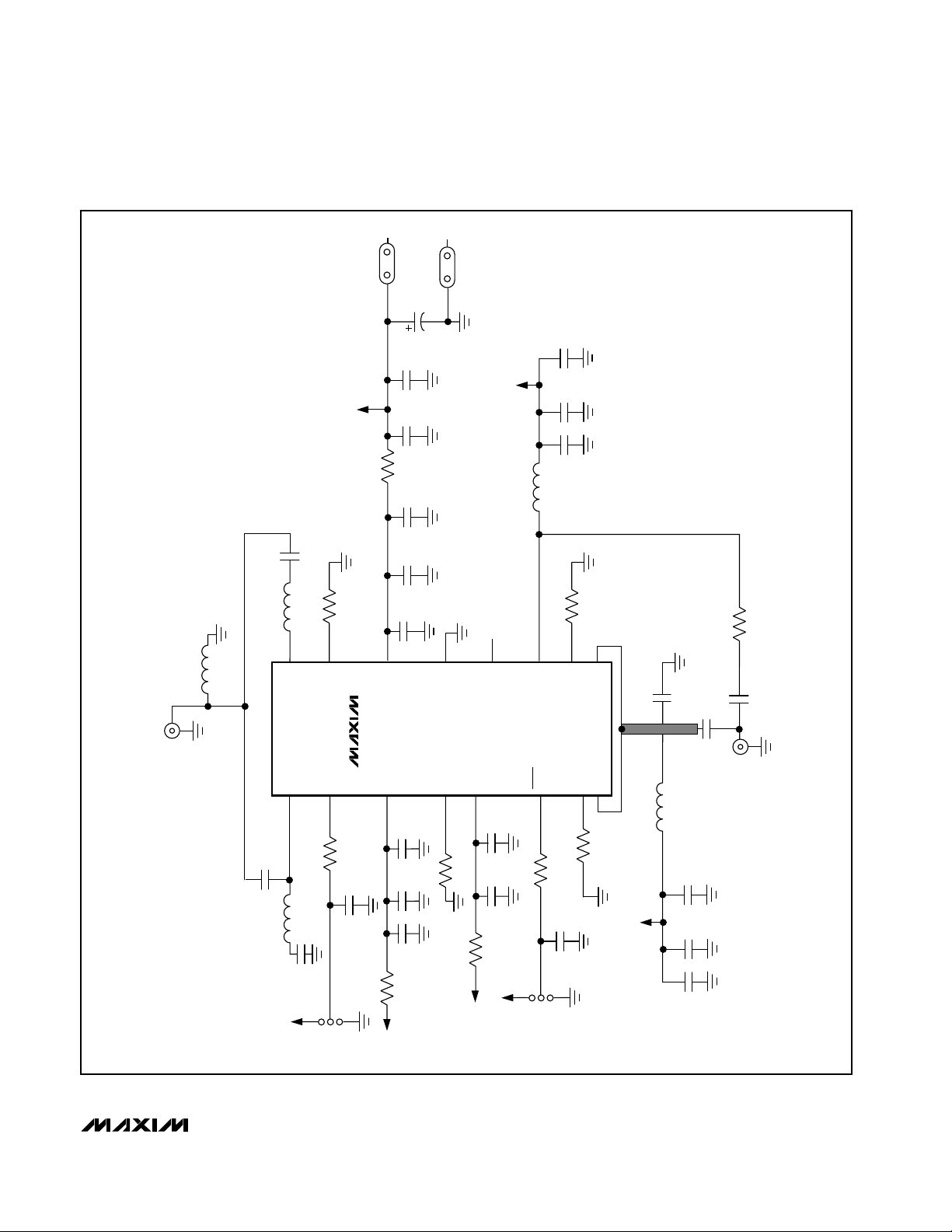
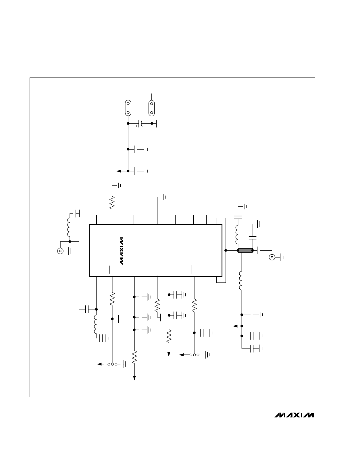
Figure 1. MAX2264 EV Kit Schematic
SMA
VCC
VCC
R8
0Ω
C18
220pF
R7
L5
1.2nH
33.2k 1%
16
15
L1
3.9nH
IN
IN0
BIA62H
14
U1
MAX2264
PWR
IN1
1
2
R1
C1
6.2pF
51k
C2
3
100pF
GND
C19
10µF
16V
C24
0.1µF
C20
0.01µF
VCC
C21
100pF
C25
0.1µF
C17
100pF
C16
0.01µF
13
CC
V
CC
V
C3
C4
0.01µF
100pF
4
R2
30.1k 1%
GND
BIAS1H
N.C.
12
NFP
CC
V
5
C5
0.01µF
C6
100pF
C14
100pF
C13
12nH
51k
11
6
R5
OUT0
SHDN
0.01µF
24.3k 1%
10
BIAS1L
7
R4
7.5k 1%
9
BIAS2L
8
OUT1
OUT1
Q1
0Ω
C11
10pF
C10
5.1pF
L2
5.6nH
C8
0.01µF
SMA
OUT
C12
4.7pF
L3
R3
VCC
L4
C26
39nH
470pF
HIGH
JU1
LOW
C7
100pF
0Ω
C22
R9
0Ω
VCC
R10
0.1µF
JU2
VCC
ON
VCC
OFF
VCC
C9
C23
100pF
0.1µF
Page 6
Evaluate: MAX2264/MAX2265/MAX2266
MAX2264/MAX2265/MAX2266 Evaluation Kits
6 _______________________________________________________________________________________
Figure 2. MAX2265 EV Kit Schematic
SMA
C19
CC
10µF
0.01µF
100pF
C3
C4
16V
0.01µF
100pF
GND
R2
35.7k 1%
13
4
GND
BIAS1
C27
5.6nH
3.3pF
C8
C11
9.1pF
C10
0.01µF
OUT
SMA
0.01µF
12
CC
V
5
C6
NFP
C5
0.01µF
100pF
11
6
N.C.
SHDN
10
9
N.C.
OUT1
L6
2.2nH
OUT1
N.C.
7
8
R3
51k
L2
VCC
C20
C21
VCC
R7
33.2k 1%
16
15
L1
5.6nH
IN
N.C.
BIAS2H
U1
14
.
N.C
MAX2265
C2
V
3
100pF
SHDN
IN1
1
2
R1
C1
5.1pF
51k
VCC
L4
C26
39nH
470pF
HIGH
JU1
LOW
C7
100pF
0Ω
C22
0.1µF
R9
0Ω
VCC
R10
VCC
JU2
ON
OFF
VCC
C9
C23
100pF
0.1µF
Page 7
Evaluate: MAX2264/MAX2265/MAX2266
MAX2264/MAX2265/MAX2266 Evaluation Kits
_______________________________________________________________________________________ 7
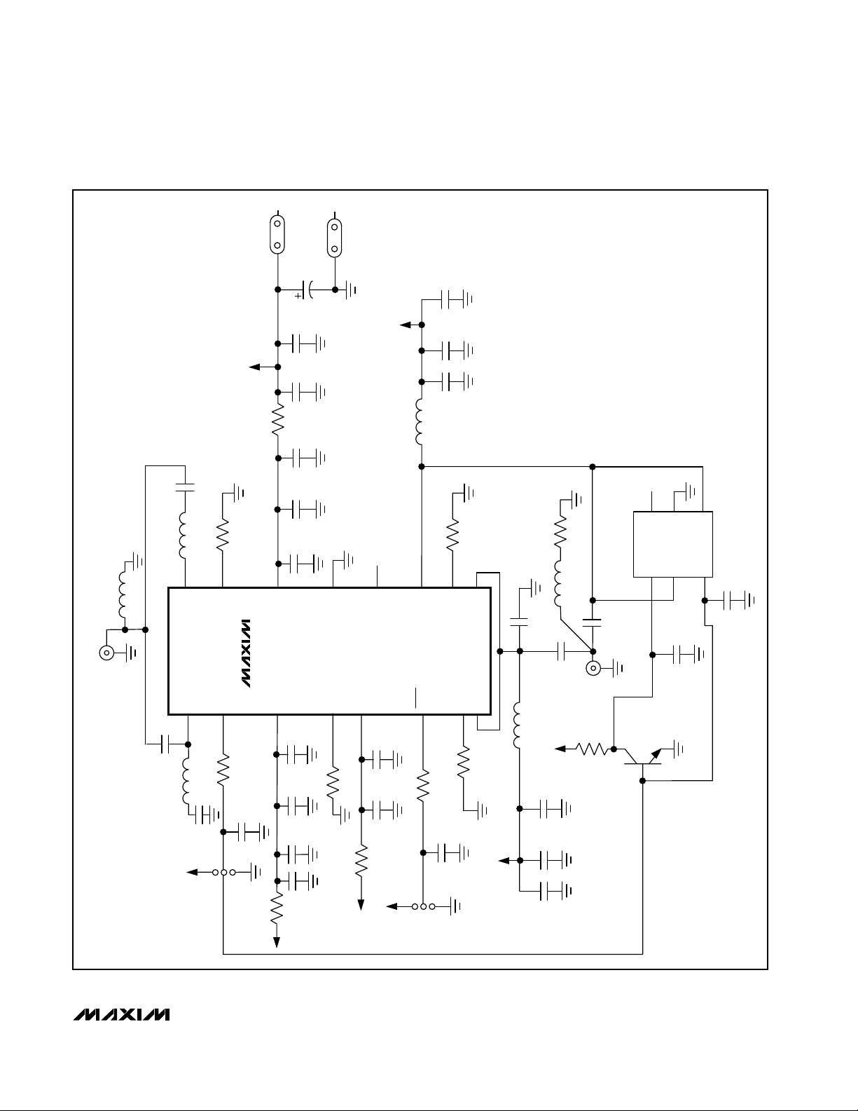
Figure 3. MAX2266 EV Kit Schematic
L1
3.9nH
SMA
C18
L5
220pF
1.2nH
16
IN0
R7
33.2k 1%
15
BIAS2
VCC
VCC
R8
0Ω
14
V
GND
C19
10µF
16V
C20
0.01µF
C21
100pF
C25
0.1µF
C17
100pF
C16
0.01µF
13
CC
GND
VCC
L3
N.C.
12
NOISE
4.7nH
11
R5
OUTL
C24
0.1µF
C14
100pF
C13
0.01µF
24.3k 1%
10
BIAS1L
9
OUTH
R11
C11
510Ω
7.5pF
L6
100nH
C12
5.1pF
2
1
6
U2
UPG152TA
5
C29
3
4
C28
U1
PWR
R1
C2
51k
100pF
LOW
MAX2266
3
R9
0Ω
VCC
C10
3.9pF
OUT
VCC
0.01µF
100pF
0.1µF
SMA
R6
10k
3
1
Q2
2
CC
V
C30
100pF
R2
C3
0.01µF
C4
100pF
C22
0.1µF
BIAS1
4
26.1k 1%
R10
CC
V
5
C5
C6
0Ω
VCC
0.01µF
100pF
VCC
SHDN
6
R3
51k
C7
JU2
ON
R4
100pF
OFF
BIAS2L
7
7.5k 1%
8
OUTH
VCC
L2
5.6nH
C8
C9
C23
IN
IN1
1
2
C1
6.2pF
L4
39nH
C26
470pF
JU1
VCC
HIGH
Page 8

Evaluate: MAX2264/MAX2265/MAX2266
MAX2264/MAX2265/MAX2266 Evaluation Kits
8 _______________________________________________________________________________________
Layout Issues
A good PC board is an essential part of an RF circuit
design. The EV kit PC board can serve as a guide for laying out a board using the MAX2264/MAX2265/MAX2266.
Keep traces carrying RF signals as short as possible to
minimize radiation and insertion loss due to the PC board.
Each VCC node on the PC board should have its own
decoupling capacitor. This minimizes supply coupling
from one section of the IC to another. Using a star topology for the supply layout, in which each VCC node on the
circuit has a separate connection to a central VCC node,
can further minimize coupling between sections of the IC.
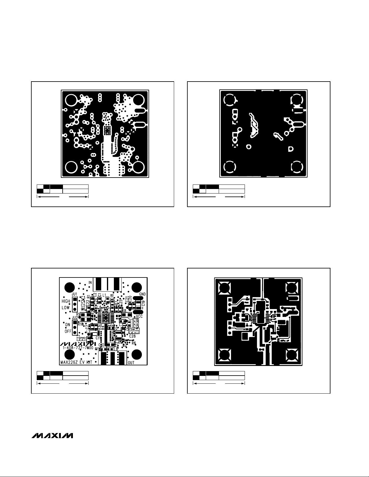
Figure 4. MAX2264/MAX2265 EV Kits—Component Placement
Guide
Figure 5. MAX2264/MAX2265 EV Kits PC Board Layout—
Component Side
Figure 6. MAX2264/MAX2265 EV Kits PC Board Layout—
Ground Plane
1.0"
1.0"
1.0"
Page 9
Evaluate: MAX2264/MAX2265/MAX2266
MAX2264/MAX2265/MAX2266 Evaluation Kits
_______________________________________________________________________________________ 9
Figure 7. MAX2264/MAX2265 EV Kits PC Board Layout—
Power Plane
Figure 8. MAX2264/MAX2265 EV Kits PC Board Layout—
Solder Side
Figure 9. MAX2266 EV Kit—Component Placement Guide
Figure 10. MAX2266 EV Kit PC Board Layout—Component
Side
1.0"
1.0"
1.0"
1.0"
Page 10

Evaluate: MAX2264/MAX2265/MAX2266
MAX2264/MAX2265/MAX2266 Evaluation Kits
10 ______________________________________________________________________________________
Figure 12. MAX2266 EV Kit PC Board Layout—Power Plane
Figure 13. MAX2266 EV Kit PC Board Layout—Solder Side
Figure 11. MAX2266 EV Kit PC Board Layout—Ground Plane
1.0"
1.0"
1.0"
Page 11

Evaluate: MAX2264/MAX2265/MAX2266
MAX2264/MAX2265/MAX2266 Evaluation Kits
______________________________________________________________________________________ 11
NOTES
Page 12

Maxim cannot assume responsibility for use of any circuitry other than circuitry entirely embodied in a Maxim product. No circuit patent licenses are
implied. Maxim reserves the right to change the circuitry and specifications without notice at any time.
12 ____________________Maxim Integrated Products, 120 San Gabriel Drive, Sunnyvale, CA 94086 408-737-7600
© 1999 Maxim Integrated Products Printed USA is a registered trademark of Maxim Integrated Products.
Evaluate: MAX2264/MAX2265/MAX2266
MAX2264/MAX2265/MAX2266 Evaluation Kits
NOTES
 Loading...