

General Description
The MAX2160/EBG tuner ICs are designed for use in
Japanese mobile digital TV (ISDB-T single-segment)
applications. The devices directly convert UHF band
signals to a low-IF using a broadband I/Q downconverter. The operating frequency range extends from
470MHz to 770MHz.
The MAX2160/EBG support both I/Q low-IF interfaces
as well as single low-IF interfaces, making the devices
universal tuners for various digital demodulator IC
implementations.
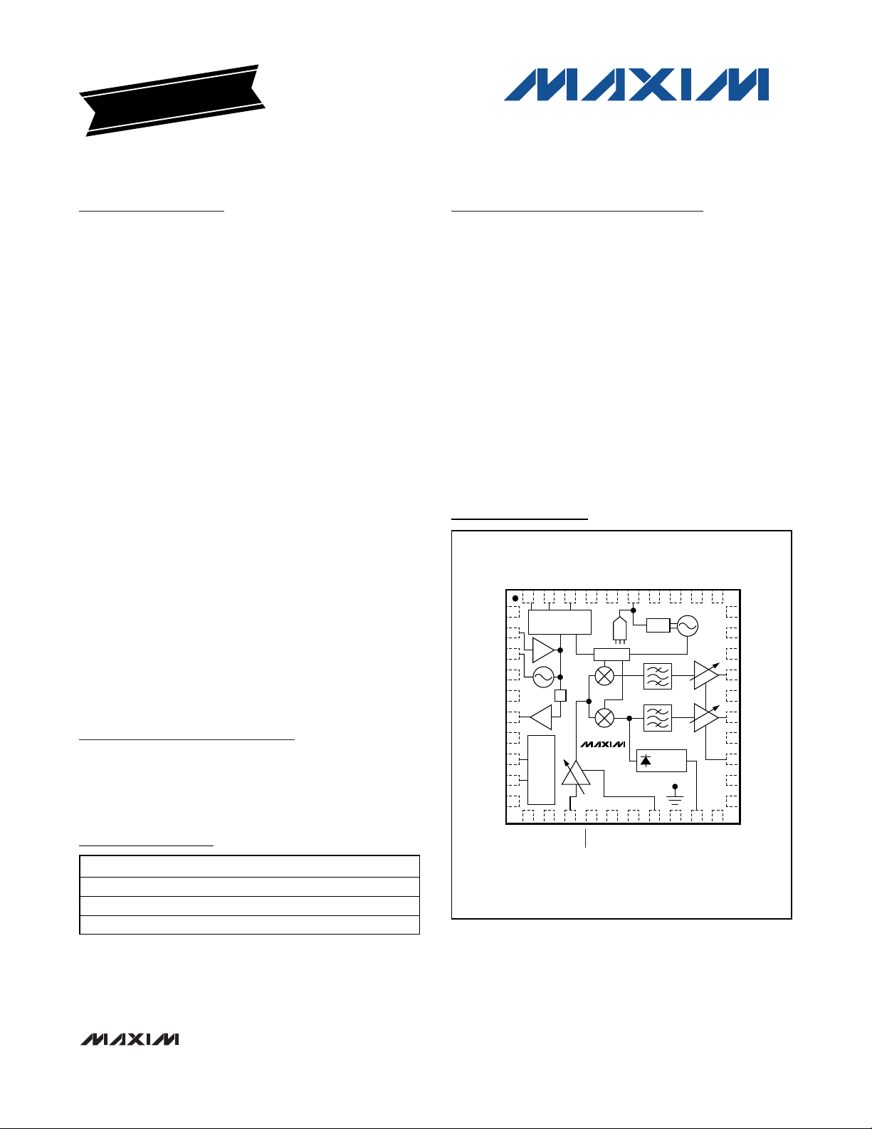
The MAX2160/EBG include an LNA, RF variable-gain
amplifiers, I and Q downconverting mixers, low-IF variablegain amplifiers, and bandpass filters providing in excess of
42dB of image rejection. The parts are capable of operating with either high-side or low-side local oscillator (LO)
injection. The MAX2160/EBG’s variable-gain amplifiers provide in excess of 100dB of gain-control range.
The MAX2160/EBG also include fully monolithic VCOs
and tank circuits, as well as a complete frequency synthesizer. The devices include a XTAL oscillator as well
as a separate TCXO input buffer. The devices operate
with XTAL/TCXO oscillators from 13MHz to 26MHz
allowing the shared use of a VC-TCXO in cellular handset applications. Additionally, a divider is provided for
the XTAL/TCXO oscillator allowing for simple and lowcost interfacing to various channel decoders.
The MAX2160/EBG are specified for operation from
-40°C to +85°C and available in a 40-pin (6mm x 6mm)
thin QFN lead-free plastic package with exposed paddle (EP), and in a 3.175mm x 3.175mm lead-free waferlevel package (WLP).
Applications
Cell Phone Mobile TVs
Personal Digital Assistants (PDAs)
Pocket TVs
Features
♦ Low Noise Figure: < 4dB Typical
♦ High Dynamic Range: -98dBm to 0dBm
♦ High-Side or Low-Side LO Injection
♦ Integrated VCO and Tank Circuits
♦ Low LO Phase Noise: Typical -88dBc/Hz at 10kHz
♦ Integrated Frequency Synthesizer
♦ Integrated Bandpass Filters
♦ 52dB Typical Image Rejection
♦ Single +2.7V to +3.3V Supply Voltage
♦ Three Low-Power Modes
♦ Two-Wire, I2C-Compatible Serial Control Interface
♦ Very Small Lead-Free WLP Package
MAX2160/MAX2160EBG
ISDB-T Single-Segment Low-IF Tuners
________________________________________________________________ Maxim Integrated Products 1
Ordering Information
19-0068; Rev 5; 10/09
For pricing, delivery, and ordering information, please contact Maxim Direct at 1-888-629-4642,
or visit Maxim’s website at www.maxim-ic.com.
+Denotes a lead(Pb)-free/RoHS-compliant package.
*EP = Exposed paddle.
EVALUATION KIT
AVAILABLE
Pin Configurations/
Functional Diagrams
Pin Configurations/Functional Diagrams continued at end of
data sheet.
PART TEMP RANGE PIN-PACKAGE
MAX2160ETL -40°C to +85°C 40 Thi n QFN - E P *
MAX2160ETL+ -40°C to +85°C 40 Thi n QFN - E P *
MAX2160EBG+ -40°C to +85°C W LP
TOP VIEW
VCCCP
CPOUT
TEST
GNDTUNE
VTUNE
GNDVCO
VCCVCO
VCOBYP
VCCMX
PWRDET
N.C.
30
29
28
27
26
25
24
23
22
21
VCCFLT
N.C.
VCCBB
N.C.
QOUT
GNDBB
IOUT
N.C.
GC2
ENTCXO
N.C.
GNDCP
40 39 38 37 36 35 34 33 32 31
1
N.C.
TCXO
XTAL
GNDXTAL
VCCXTAL
XTALOUT
VCCDIG
SDA
SCL
LTC
FREQUENCY
SYNTHESIZER
2
3
4
5
6
7
8
9
10
÷
AND CONTROL
INTERFACE LOGIC
11 12 13 14 15 16 17 18 19 20
N.C.
RFIN
VCCBIAS
DIV4
MAX2160
SHDN
ADC
N.C.
TQFN
TANK
PWRDET
EP
GC1
VCCLNA
MAX2160/MAX2160EBG
ISDB-T Single-Segment Low-IF Tuners
2 _______________________________________________________________________________________
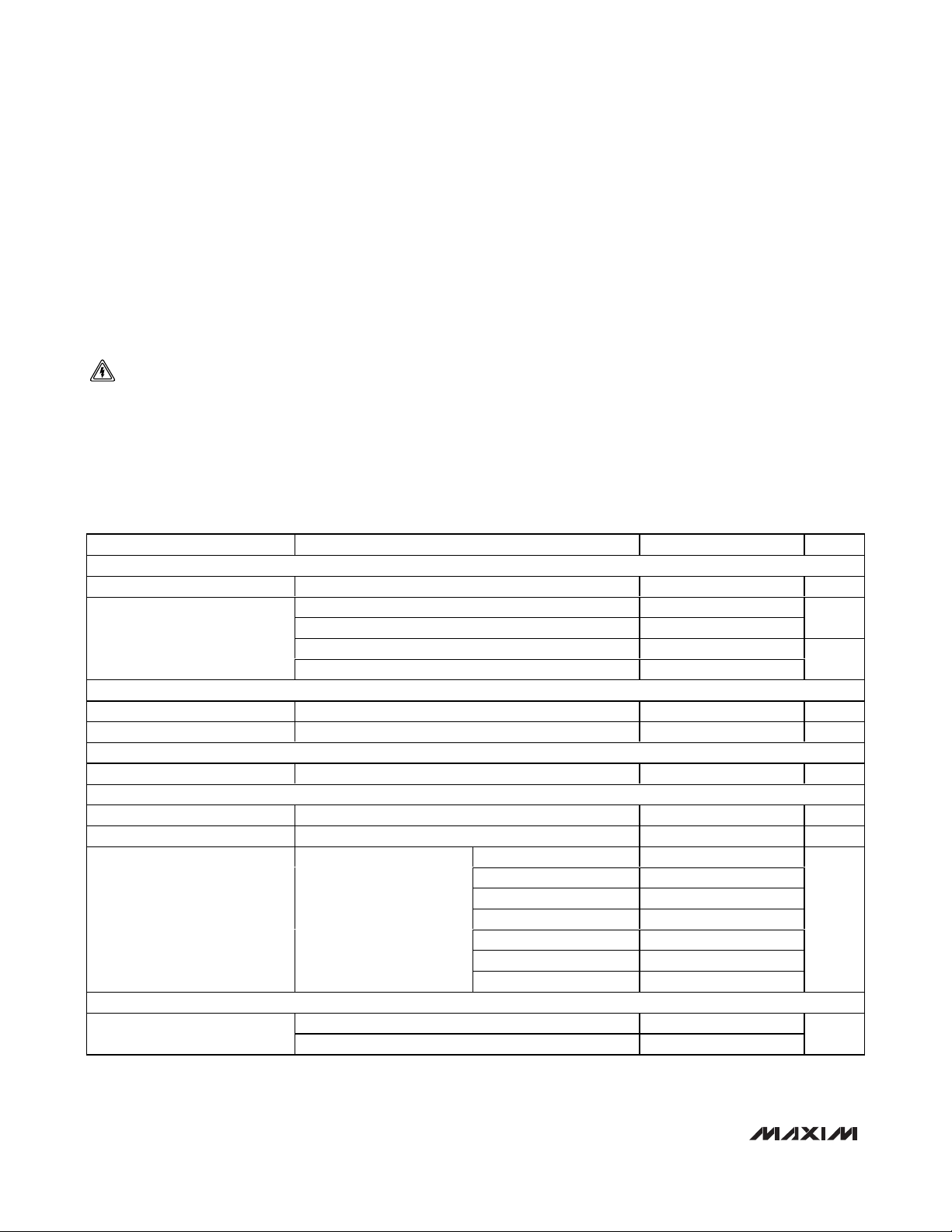
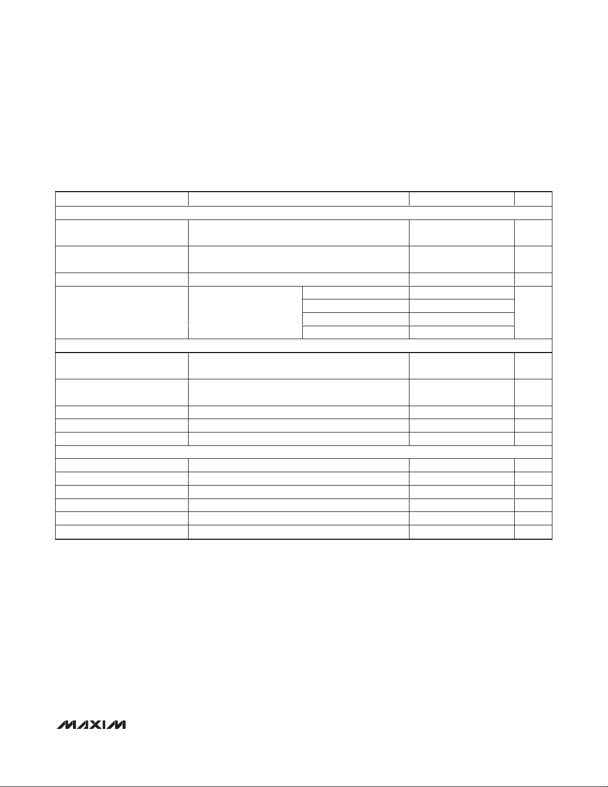
ABSOLUTE MAXIMUM RATINGS
DC ELECTRICAL CHARACTERISTICS
(MAX2160 EV kit, VCC= +2.7V to +3.3V, V
GC1
= V
GC2
= 0.3V (maximum gain), no RF input signals at RFIN, baseband I/Os are open
circuited and VCO is active with f
LO
= 767.714MHz, registers set according to the recommended default register conditions of
Tables 2–11, T
A
= -40°C to +85°C, unless otherwise noted. Typical values are at VCC= +2.85V, TA= +25°C, unless otherwise
noted.) (Note 1)
Stresses beyond those listed under “Absolute Maximum Ratings” may cause permanent damage to the device. These are stress ratings only, and functional
operation of the device at these or any other conditions beyond those indicated in the operational sections of the specifications is not implied. Exposure to
absolute maximum rating conditions for extended periods may affect device reliability.
All VCC_ Pins to GND............................................-0.3V to +3.6V
All Other Pins to GND.................................-0.3V to (V
CC
+ 0.3V)
RFIN, Maximum RF Input Power ....................................+10dBm
ESD Rating...........................................................................±1kV
Short-Circuit Duration
IOUT, QOUT, CPOUT, XTALOUT, PWRDET, SDA,
TEST, LTC, VCOBYP ...........................................................10s
Continuous Power Dissipation (T
A
= +70°C)
40-Pin Thin QFN (derate 35.7mW/°C above +70°C)....2857mW
WLP (derate 10.8mW/°C above +70°C).........................704mW
Operating Temperature Range ...........................-40°C to +85°C
Junction Temperature......................................................+150°C
Storage Temperature Range .............................-65°C to +150°C
Lead Temperature (soldering, 10s) .................................+300°C
CAUTION! ESD SENSITIVE DEVICE
SUPPLY
Supply Voltage 2.7 2.85 3.3 V
PARAMETER CONDITIONS MIN TYP MAX UNITS
Supply Current (See Tables 15
and 16)
ANALOG GAIN-CONTROL INPUTS (GC1, GC2)
Input Voltage Range Maximum gain = 0.3V 0.3 2.7 V
Input Bias Current -15 +15 µA
VCO TUNING VOLTAGE INPUT (VTUNE)
Input Voltage Range 0.4 2.3 V
VTUNE ADC
Resolution 3 bits
Input Voltage Range 0.3 2.4 V
Reference Ladder Trip Point ADC read bits
LOCK TIME CONSTANT OUTPUT (LTC)
Source Current
Receive mode, SHDN = VCC , BBL[1:0] = 00 44 53.5
Standby mode, bit STBY = 1 2 4
Power-down mode, bit PWDN = 1, EPD = 0 5 40
Shutdown mode, SHDN = GND 0 10
Bit LTC = 0 1
Bit LTC = 1 2
110 to 111 VCC - 0.4
101 to 110 1.9
100 to 101 1.7
011 to 100 1.3
010 to 011 0.9
001 to 010 0.6
000 to 001 0.4
mA
µA
V
µA
MAX2160/MAX2160EBG
ISDB-T Single-Segment Low-IF Tuners
_______________________________________________________________________________________ 3
DC ELECTRICAL CHARACTERISTICS (continued)
(MAX2160 EV kit, VCC= +2.7V to +3.3V, V
GC1
= V
GC2
= 0.3V (maximum gain), no RF input signals at RFIN, baseband I/Os are open
circuited and VCO is active with f
LO
= 767.714MHz, registers set according to the recommended default register conditions of
Tables 2–11, T
A
= -40°C to +85°C, unless otherwise noted. Typical values are at VCC= +2.85V, TA= +25°C, unless otherwise
noted.) (Note 1)
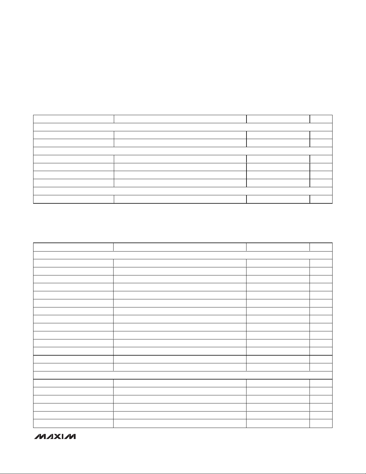
AC ELECTRICAL CHARACTERISTICS
(MAX2160 EV kit, VCC= +2.7V to +3.3V, fRF= 767.143MHz, fLO= 767.714MHz, fBB= 571kHz, f
XTAL
= 16MHz, V
GC1
= V
GC2
= 0.3V
(maximum gain), registers set according to the recommended default register conditions of Tables 2–11, RF input signals as specified, baseband output load as specified, T
A
= -40°C to +85°C, unless otherwise noted. Typical values are at VCC= +2.85V,
T
A
= +25°C, unless otherwise noted.) (Note 1)
PARAMETER CONDITIONS MIN TYP MAX UNITS
SHUTDOWN CONTROL (SHDN)
Input-Logic-Level High 0.7 x V
Input-Logic-Level Low 0.3 x V
2-WIRE SERIAL INPUTS (SCL, SDA)
Clock Frequency 400 kHz
Input-Logic-Level High 0.7 x V
Input-Logic-Level Low 0.3 x V
Input Leakage Current Digital inputs = GND or V
2-WIRE SERIAL OUTPUT (SDA)
Output-Logic-Level Low 0.2 V
CC
CC
CC
CC
CC
±0.1 ±1 µA
V
V
V
V
PARAMETER CONDITIONS MIN TYP MAX UNITS
MAIN SIGNAL PATH PERFORMANCE
Input Frequency Range 470 770 MHz
Minimum Input Signal 13-segment input -98 dBm
Maximum Voltage Gain CW tone, V
Minimum Voltage Gain CW tone, V
RF Gain-Control Range 0.3V < V
Baseband Gain-Control Range 0.3V < V
In-Band Input IP3 (Note 2) +4 dBm
Out-of-Band Input IP3 (Note 3) +16.7 dBm
Input IP2 (Note 4) +16 dBm
Input P
1dB
Noise Figure V
Image Rejection 42 52 dB
Minimum RF Input Return Loss fRF = 620MHz, 50Ω system 14 dB
LO Leakage at RFIN -100 dBm
IF POWER DETECTOR
Resolution 3 bits
Minimum RF Attack Point Power at RFIN -62 dBm
Maximum RF Attack Point Power at RFIN -48 dBm
Detector Bandwidth 3dB RF bandwidth ±35 MHz
Output Compliance Range 0.3 2.7 V
Response Time C14 = 10nF 0.1 ms
CW tone, V
GC1
= V
GC1
GC1
< 2.7V 38 43 dB
GC1
< 2.7V 57 67 dB
GC2
GC1
= V
= 0.3V, TA = +25°C (Note 5) 3.8 5 dB
GC2
= 0.3V, bit MOD = 1 102 dB
GC2
= V
= 2.7V, bit MOD = 0 4 dB
GC2
= V
= 2.7V, bit MOD = 0 0 dBm
GC2
MAX2160/MAX2160EBG
ISDB-T Single-Segment Low-IF Tuners
4 _______________________________________________________________________________________
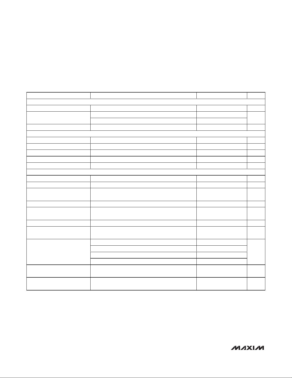
AC ELECTRICAL CHARACTERISTICS (continued)
(MAX2160 EV kit, VCC= +2.7V to +3.3V, fRF= 767.143MHz, fLO= 767.714MHz, fBB= 571kHz, f
XTAL
= 16MHz, V
GC1
= V
GC2
= 0.3V
(maximum gain), registers set according to the recommended default register conditions of Tables 2–11, RF input signals as specified, baseband output load as specified, T
A
= -40°C to +85°C, unless otherwise noted. Typical values are at VCC= +2.85V,
T
A
= +25°C, unless otherwise noted.) (Note 1)
LOW-IF BANDPASS FILTERS
Center Frequency 571 kHz
Frequency Response (Note 5)
Group Delay Variation Up to 1dB bandwidth ±100 ns
BASEBAND OUTPUT CHARACTERISTICS
Nominal Output-Voltage Swing R
I/Q Amplitude Imbalance (Note 6) ±1.5 dB
I/Q Quadrature Phase Imbalance ±2 deg
Output Gain Step Bit MOD transition from 0 to 1 +7 dB
I/Q Output Impedance Real Z
FREQUENCY SYNTHESIZER
RF-Divider Frequency Range 470 770 MHz
RF-Divider Range (N) 829 5374
Reference-Divider Frequency
Range
Reference-Divider Range (R) 22 182
Phase-Detector Comparison
Frequency
PLL-Referred Phase Noise Floor TA = +25°C, f
Comparison Frequency Spurious
Products
Charge-Pump Output Current
(Note 5)
Charge-Pump Compliance
Range
Charge-Pump Source/Sink
Current Matching
PARAMETER CONDITIONS MIN TYP MAX UNITS
±380kHz offset from center frequency -6 -1.5
1.3MHz -36
LOAD
Bit EPB = 1 -52 dBc
Bits CP[1:0] = 00 1.25 1.5 1.75
Bits CP[1:0] = 01 1.65 2.0 2.35
Bits CP[1:0] = 10 2.10 2.5 2.90
Bits CP[1:0] = 11 2.50 3 3.50
±10% variation from current at VTUNE = 1.35V 0.4 2.2 V
VTUNE = 1.35V -10 +10 %
= 10kΩ || 10pF 0.5 V
O
= 285.714kHz -155 dBc/Hz
COMP
30 Ω
13 26 MHz
1/7 4/7 MHz
dB
P-P
mA
MAX2160/MAX2160EBG
ISDB-T Single-Segment Low-IF Tuners
_______________________________________________________________________________________ 5
AC ELECTRICAL CHARACTERISTICS (continued)
(MAX2160 EV kit, VCC= +2.7V to +3.3V, fRF= 767.143MHz, fLO= 767.714MHz, fBB= 571kHz, f
XTAL
= 16MHz, V
GC1
= V
GC2
= 0.3V
(maximum gain), registers set according to the recommended default register conditions of Tables 2–11, RF input signals as specified, baseband output load as specified, T
A
= -40°C to +85°C, unless otherwise noted. Typical values are at VCC= +2.85V,
T
A
= +25°C, unless otherwise noted.) (Note 1)
Note 1: Min and max values are production tested at TA= +25°C and +85°C. Min and max limits at TA= -40°C are guaranteed by
design and characterization. Default register settings are not production tested; load all registers no sooner than 100µs
after power-up.
Note 2: In-band IIP3 is measured with two tones at f
LO
- 100kHz and fLO- 200kHz at a power level of -23dBm/tone. GC1 is set for
maximum attenuation (V
GC1
= 2.7V) and GC2 is adjusted to achieve 250mV
P-P
/tone at the I/Q outputs for an input desired
level of -23dBm.
Note 3: Out-of-band IIP3 is measured with two tones at f
RF
+ 6MHz and fRF+ 12MHz at a power level of -15dBm/tone. GC1 is set
for maximum attenuation (V
GC1
= 2.7V) and GC2 is adjusted to achieve 0.5V
P-P
at the I/Q outputs for an input desired level
of -50dBm. fRFis set to 767MHz + 1/7MHz = 767.143MHz.
Note 4: GC1 is set for maximum attenuation (V
GC1
= 2.7V). GC2 is adjusted to give the nominal I/Q output voltage level (0.5V
P-P
)
for a -50dBm desired tone at f
RF
= 550MHz. Two tones, 220MHz and 770MHz at -15dBm/tone, are then injected and the
571kHz IM2 levels are measured (with a 550.571MHz LO) at the I/Q outputs and IP2 is then calculated.
Note 5: Guaranteed by design and characterization.
Note 6: Guaranteed and tested at T
A
= +25°C and +85°C only.
PARAMETER CONDITIONS MIN TYP MAX UNITS
VOLTAGE-CONTROLLED OSCILLATOR AND LO GENERATION
Guaranteed VCO Frequency
Range
Guaranteed LO Frequency
Range
= -40°C to +85°C 1880 3080 MHz
T
A
= -40°C to +85°C 470 770 MHz
T
A
Tuning Voltage Range 0.4 2.3 V
f
= 1kHz -80
OFFSET
f
= 10kHz -87.5
LO Phase Noise
0.4V < VTUNE < 2.3V,
T
= -40°C to +85°C
A
OFFSET
f
= 100kHz -107
OFFSET
f
= 1MHz -128
OFFSET
XTAL OSCILLATOR INPUT (TCXO AND XTAL)
XTAL Oscillator Frequency
Range
XTAL Minimum Negative
Resistance
Parallel resonance mode crystal 13 26 MHz
16MHz < f
< 18MHz (Note 5) 885 Ω
XTAL
XTAL Nominal Input Capacitance 13.3 pF
TCXO Input Level AC-coupled sine-wave input 0.4 1.5 V
TCXO Minimum Input Impedance 10 kΩ
REFERENCE OSCILLATOR BUFFER OUTPUT (XTALOUT)
Output Frequency Range 1 26 MHz
Output-Buffer Divider Range 1 26
Output-Voltage Swing 0.7 V
Output Load 200 || 4 kΩ || pF
Output Duty Cycle 50 %
Output Impedance 160 Ω
dBc/Hz
P-P
P-P
MAX2160/MAX2160EBG
ISDB-T Single-Segment Low-IF Tuners
6 _______________________________________________________________________________________
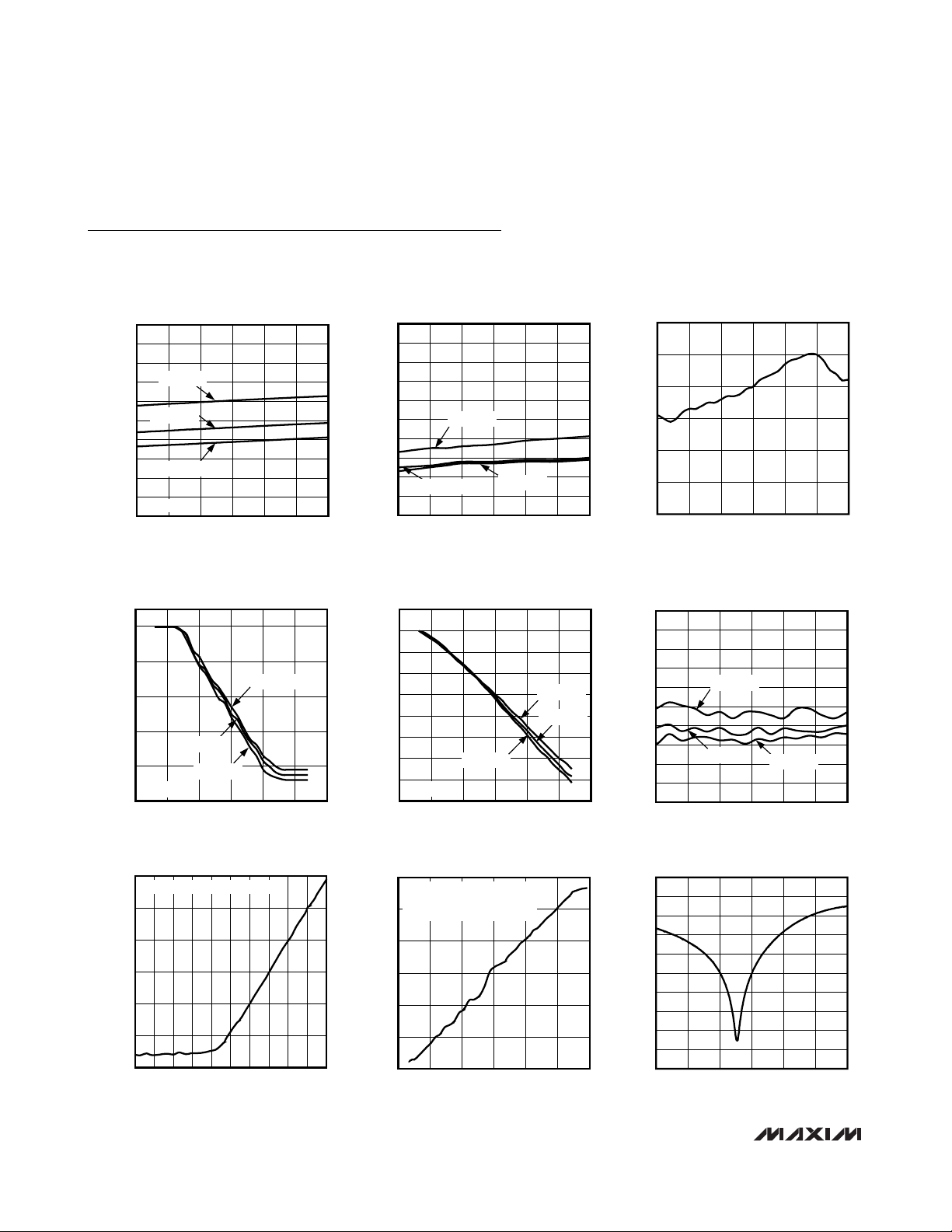
Typical Operating Characteristics
(MAX2160 EV kit, TQFN package, VCC= +2.85V, default register settings, V
GC1
= V
CG2
= 0.3V, V
IOUT
= V
QOUT
= 0.5V
P-P
,
f
LO
= 767.714MHz, TA= +25°C, unless otherwise noted.)
RECEIVE-MODE SUPPLY CURRENT
vs. SUPPLY VOLTAGE
MAX2160 toc01
SUPPLY VOLTAGE (V)
SUPPLY CURRENT (mA)
3.23.13.02.92.8
41
42
43
44
45
46
47
48
49
50
40
2.7 3.3
TA = +85°C
TA = +25°C
TA = -40°C
BBL[1:0] = 00
SHUTDOWN-MODE SUPPLY CURRENT
vs. SUPPLY VOLTAGE
MAX2160 toc02
SUPPLY VOLTAGE (V)
SUPPLY CURRENT (µA)
3.23.13.02.92.8
0.1
0.2
0.3
0.4
0.5
0.6
0.7
0.8
0.9
1.0
0
2.7 3.3
TA = +85°C
TA = +25°C
TA = -40°C
VOLTAGE GAIN vs. FREQUENCY
MAX2160 toc03
FREQUENCY (MHz)
GAIN (dB)
720670620570520
108
109
110
111
112
113
107
470 770
RELATIVE GC1 GAIN RANGE
vs. GC1 VOLTAGE
MAX2160 toc04
V
GC1
(V)
RELATIVE GC1 GAIN RANGE (dB)
2.52.01.51.00.5
-40
-30
-20
-10
0
-50
0 3.0
TA = +25°C
TA = +85°C
FIXED V
GC2
TA = -40°C
RELATIVE GC2 GAIN RANGE
vs. GC2 VOLTAGE
MAX2160 toc05
V
GC2
(V)
RELATIVE GC2 GAIN RANGE (dB)
2.52.01.51.00.5
-70
-60
-50
-40
-30
-20
-10
0
10
-80
03.0
TA = +85°C
TA = -40°C
FIXED V
GC1
TA = +25°C
NOISE FIGURE vs. FREQUENCY
MAX2160 toc06
FREQUENCY (MHz)
NOISE FIGURE (dB)
720670620570520
1
2
3
4
5
6
7
8
9
10
0
470 770
TA = +25°C
TA = +85°C
TA = -40°C
NOISE FIGURE vs. INPUT POWER
MAX2160 toc07
INPUT POWER (dBm)
NOISE FIGURE (dB)
-10-20-30-40-50-60-70-80-90
10
20
30
40
50
60
0
-100 0
CLOSED-LOOP POWER CONTROL
IN-BAND IIP3 vs. INPUT POWER
MAX2160 toc08
INPUT POWER (dBm)
IN-BAND IIP3 (dBm)
-20-40-60-80-100
-80
-60
-40
-20
0
20
-100
-120 0
CLOSED-LOOP POWER CONTROL
f
LO
= 767.714MHz
f
1
= fLO - 100kHz, f2 = fLO - 200kHz
INPUT RETURN LOSS vs. FREQUENCY
MAX2160 toc09
FREQUENCY (MHz)
INPUT RETURN LOSS (dB)
720670620570520
45
40
35
30
25
20
15
10
5
0
50
470 770
MAX2160/MAX2160EBG
ISDB-T Single-Segment Low-IF Tuners
_______________________________________________________________________________________ 7
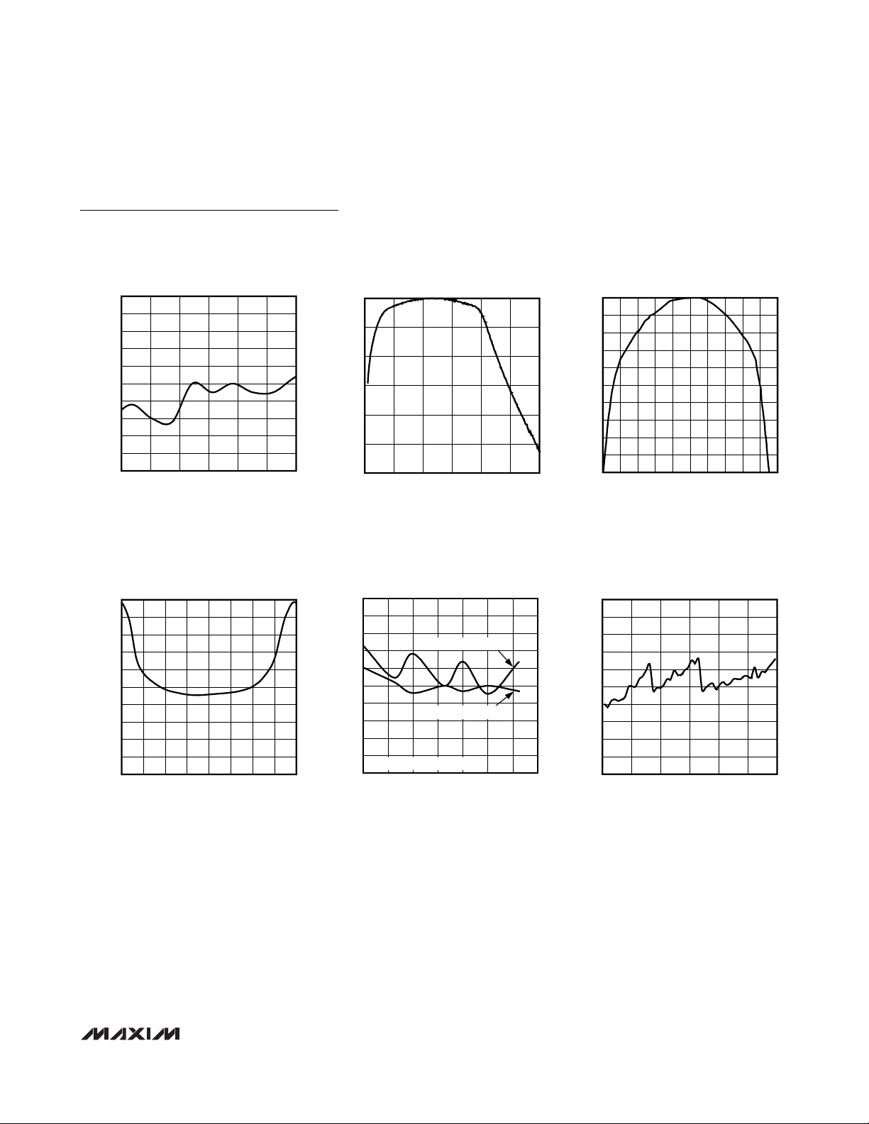
Typical Operating Characteristics (continued)
(MAX2160 EV kit, TQFN package, VCC= +2.85V, default register settings, V
GC1
= V
CG2
= 0.3V, V
IOUT
= V
QOUT
= 0.5V
P-P
,
f
LO
= 767.714MHz, TA= +25°C, unless otherwise noted.)
GROUP-DELAY VARIATION
vs. BASEBAND FREQUENCY
MAX2160 toc13
FREQUENCY (kHz)
GROUP-DELAY VARIATION (ns)
900800600 700400 500300
-800
-600
-400
-200
0
200
400
600
800
1000
-1000
200 1000
IF FILTER 3dB FREQUENCY
vs. TEMPERATURE
MAX2160 toc14
TEMPERATURE (°C)
NORMALIZED 3dB FREQUENCY (%)
806020 400-20
-4
-3
-2
-1
0
1
2
3
4
5
-5
-40 100
LOWER 3dB CUTOFF
NORMALIZED TO TA = +25°C
UPPER 3dB CUTOFF
PHASE NOISE AT 10kHz OFFSET
vs. CHANNEL FREQUENCY
MAX2160 toc16
CHANNEL FREQUENCY (MHz)
PHASE NOISE AT 10kHz OFFSET (dBc/Hz)
720670620570520
-98
-96
-94
-92
-90
-88
-86
-84
-82
-80
-100
470 770
LO-TO-RFIN LEAKAGE vs. FREQUENCY
-105
-106
-107
-108
-109
-110
-111
-112
LO-TO-RFIN LEAKAGE (dBm)
-113
-114
-115
470 770
FREQUENCY (MHz)
0
-10
MAX2160 toc10
-20
-30
-40
NORMALIZED GAIN (dB)
-50
720670620570520
-60
0 1500
IF FILTER
FREQUENCY RESPONSE
FREQUENCY (kHz)
12501000750500250
0
-1
MAX2160 toc11
-2
-3
-4
-5
-6
-7
NORMALIZED GAIN (dB)
-8
-9
-10
IF FILTER PASSBAND
FREQUENCY RESPONSE
100 1100
FREQUENCY (kHz)
1000900700 800300 400 500 600200
MAX2160 toc12
MAX2160/MAX2160EBG
ISDB-T Single-Segment Low-IF Tuners
8 _______________________________________________________________________________________
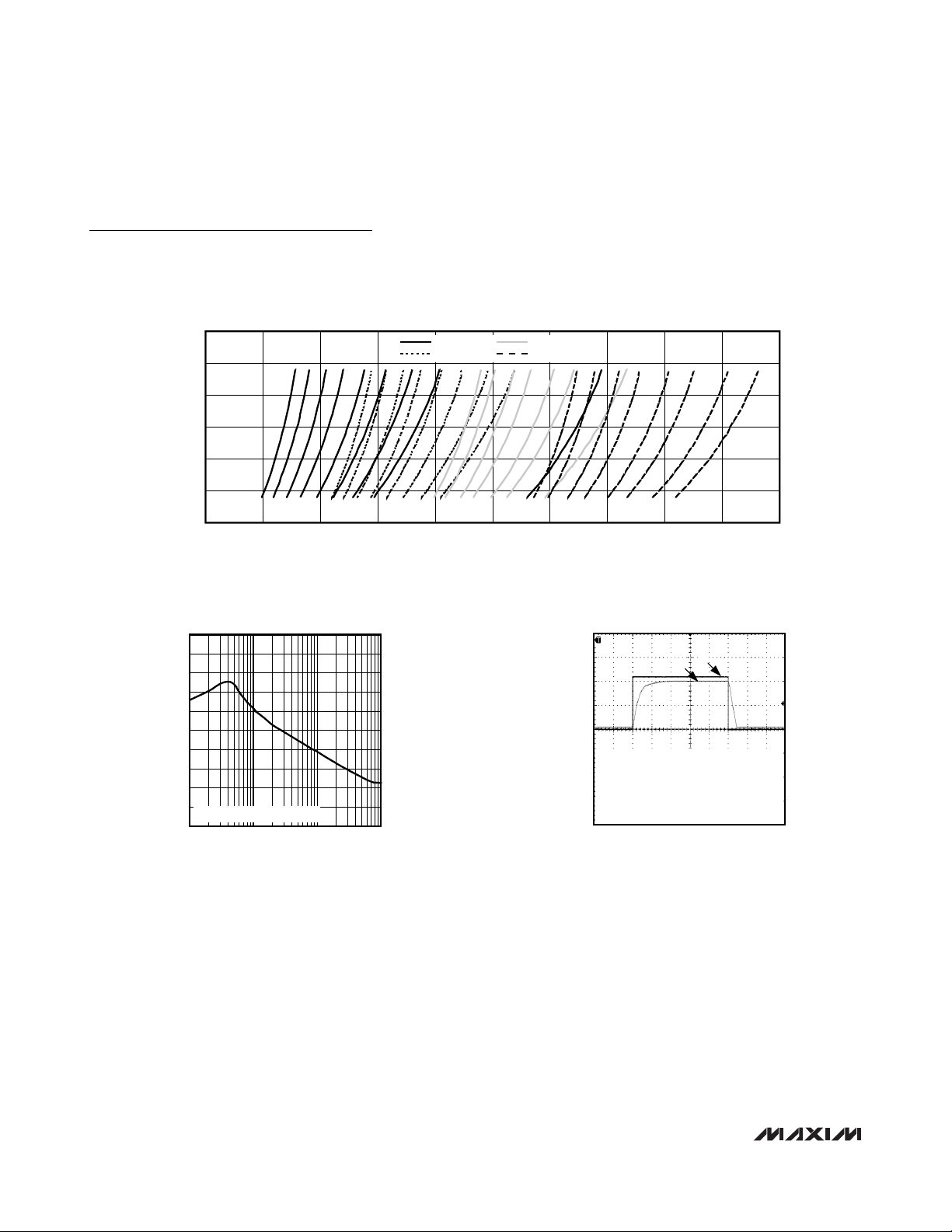
Typical Operating Characteristics (continued)
(MAX2160 EV kit, TQFN package, VCC= +2.85V, default register settings, V
GC1
= V
CG2
= 0.3V, V
IOUT
= V
QOUT
= 0.5V
P-P
,
f
LO
= 767.714MHz, TA= +25°C, unless otherwise noted.)
TUNING VOLTAGE vs. VCO FREQUENCY
MAX2160 toc15
VCO FREQUENCY (MHz)
V
TUNE
(V)
800750700650600550500450400
0.5
1.0
1.5
2.0
2.5
3.0
0
350 850
VCO 1, SB 0-7
VCO 2, SB 0-7
VCO 3, SB 0-7
VCO 4, SB 0-7
PHASE NOISE vs. OFFSET FREQUENCY
MAX2160 toc17
OFFSET FREQUENCY (kHz)
PHASE NOISE (dBc/Hz)
10010
-140
-130
-120
-110
-100
-90
-80
-70
-60
-50
-150
1 1000
fLO = 575.714MHz (VCO 2, SB1)
POWER-DETECTOR RESPONSE TIME
MAX2160 toc18
A: LOW = -60dBm RF INPUT POWER
HIGH = -20dBm RF INPUT POWER
B: POWER-DETECTOR OUTPUT VOLTAGE,
0.5V/div, CLOSED-LOOP POWER-CONTROL
DEFAULT ATTACK POINT
0.01µF LOOP CAPACITOR
200µs/div
A
B

MAX2160/MAX2160EBG
ISDB-T Single-Segment Low-IF Tuners
_______________________________________________________________________________________ 9
Pin Description
PIN BUMP NO.
TQFN WLP
1, 11, 15, 21,
24, 28, 30, 31
2 2 TCXO
3 11 XTAL
4 — GNDXTAL Crystal-Oscillator Circuit Ground. Connect to the PC board ground plane.
5 12 VCCXTAL
6 4 XTALOUT
7 5 VCCDIG
8 14 SDA 2-Wire Serial Data Interface. Requires a pullup resistor to VCC.
9 7 SCL 2-Wire Serial Clock Interface. Requires a pullup resistor to VCC.
10 19 LTC
29, 33, 34, 35,
36, 45, 46
NAME DESCRIPTION
N.C. No Connection. Connect to the PC board ground plane.
High-Impedance Buffer for External TCXO. When ENTCXO is pulled high, this input
is enabled for use with an external TCXO and the internal crystal oscillator is
disabled. Requires a DC-blocking capacitor.
Crystal-Oscillator Interface. When ENTCXO is pulled low, this input is enabled for use
with an external parallel resonance mode crystal. See the Typical Operating Circuit.
DC Power Supply for Crystal-Oscillator Circuits. Connect to a +2.85V low-noise
supply. Bypass to GND with a 100pF capacitor connected as close to the pin as
possible. Do not share capacitor ground vias with other ground connections.
Crystal Oscillator Buffer Output. A DC-blocking capacitor must be used when driving
external circuitry.
DC Power Supply for Digital Logic Circuits. Connect to a +2.85V low-noise supply.
Bypass to GND with a 100pF capacitor connected as close to the pin as possible.
Do not share capacitor ground vias with other ground connections.
PLL Lock Time Constant. LTC sources current to an external charging capacitor to
set the time constant for the VCO autoselect (VAS) function. See the Loop Time
Constant Pin section in the Applications Information.
DC Power Supply for Bias Circuits. Connect to a +2.85V low-noise supply. Bypass to
12 9 VCCBIAS
13 17 RFIN Wideband 50Ω RF Input. Connect to an RF source through a DC-blocking capacitor.
14 22 SHDN
16 24 VCCLNA
17 25 GC1
18 28 VCCMX
19 38 PWRDET
GND with a 100pF capacitor connected as close to the pin as possible. Do not share
capacitor ground vias with other ground connections.
Device Shutdown. Logic-low turns off the entire device including the 2-wire
compatible bus. SHDN overrides all software shutdown modes.
DC Power Supply for LNA. Connect to a +2.85V low-noise supply. Bypass to GND
with a 100pF capacitor connected as close to the pin as possible. Do not share
capacitor ground vias with other ground connections.
RF Gain-Control Input. High-impedance analog input, with a 0.3V to 2.7V operating
range. V
DC Power Supply for RF Mixer Circuits. Connect to a +2.85V low-noise supply.
Bypass to GND with a 100pF capacitor connected as close to the pin as possible.
Do not share capacitor ground vias with other ground connections.
Power-Detector Output. See the IF Power Detector section in the Applications
Information.
= 0.3V corresponds to the maximum gain setting.
GC1

MAX2160/MAX2160EBG
ISDB-T Single-Segment Low-IF Tuners
10 ______________________________________________________________________________________
Pin Description (continued)
PIN BUMP NO.
TQFN WLP
20 39 VCCFLT
22 37 ENTCXO
23 47 GC2
25 44 IOUT In-Phase Low-IF Output. Requires a DC-blocking capacitor.
26 — GNDBB Ground for Baseband Circuits. Connect to the PC board ground plane.
27 43 QOUT Quadrature Low-IF Output. Requires a DC-blocking capacitor.
29 41 VCCBB
NAME DESCRIPTION
DC Power Supply for Baseband Filter Circuits. Connect to a +2.85V low-noise
supply. Bypass to GND with a 100pF capacitor connected as close to the pin as
possible. Do not share capacitor ground vias with other ground connections.
XTAL/TCXO Select. Logic-high enables the TCXO input and disables the XTAL input.
Logic-low disables the TCXO input and enables the XTAL input. This pin is internally
pulled up to V
Baseband Gain-Control Input. High-impedance analog input, with a 0.3V to 2.7V
operating range. V
DC Power Supply for Baseband Circuits. Connect to a +2.85V low-noise supply.
Bypass to GND with a 100pF capacitor connected as close to the pin as possible.
Do not share capacitor ground vias with other ground connections.
CC
.
= 0.3V corresponds to the maximum gain setting.
GC2
32 30 VCOBYP
33 26 VCCVCO
34 23 GNDVCO
35 32 VTUNE
36 20 GNDTUNE
37 18 TEST Test Output. Used as a test output for various internal blocks. See Table 2.
38 16 CPOUT
39 10 VCCCP
40 1 GNDCP
EP — GND
—
— 21 GNDLNA Ground for LNA. Connect to ground with trace.
3, 6, 8, 13, 15,
27, 31, 40, 42
GND Ground. Connect to the PC board ground plane.
Internal VCO Bias Bypass. Bypass directly to GNDVCO with a 470nF capacitor
connected as close to the pin as possible. Do not share capacitor ground vias with
other ground connections. See the Layout Considerations section.
DC Power Supply for VCO Circuits. Connect to a +2.85V low-noise supply. Bypass
directly to GNDVCO with a 100pF capacitor connected as close to the pin as
possible. Do not share capacitor ground vias with other ground connections.
VCO Circuit Ground. Connect to the PC board ground plane. See the Layout
Considerations section.
High-Impedance VCO Tune Input. Connect the PLL loop filter output directly to this
pin with the shortest connection as possible.
Ground for VTUNE. Connect to the PC board ground plane. See the Layout
Considerations section.
Charge-Pump Output. Connect this output to the PLL loop filter input with the
shortest connection possible.
DC Power Supply for Charge-Pump Circuits. Connect to a +2.85V low-noise supply.
Bypass to GND with a 100pF capacitor connected as close to the pin as possible.
Do not share capacitor ground vias with other ground connections.
Charge-Pump Circuit Ground. Connect to the PC board ground plane. See the
Layout Considerations section.
Exposed Paddle (TQFN Only). Solder evenly to the board’s ground plane for proper
operation.

MAX2160/MAX2160EBG
ISDB-T Single-Segment Low-IF Tuners
______________________________________________________________________________________ 11
Detailed Description
All registers must be written after power-up and no earlier than 100µs after power-up.
Register Descriptions
The MAX2160/EBG include eight programmable registers and two read-only registers. The eight programma-
ble registers include a test register, a PLL register, a
VCO register, a control register, a XTAL divide register,
an R-divider register, and two N-divider registers. The
read-only registers include two status registers.
Table 1. Register Configuration
Table 2. Test Register
REGISTER
NUMBER
1 TEST WRITE 0x00 TUN2 TUN1 TUN0 FLTS MXSD D2 D1 D0
2 PLL WRITE 0x01 CP1 CP0 CPS EPB RPD NPD TON VAS
3 VCO WRITE 0x02 VCO1 VCO0 VSB2 VSB1 VSB0 ADL ADE LTC
4 CONTROL WRITE 0x03 MOD BBL1 BBL0 HSLS PD2 PD1 PD0 EPD
5 XTAL DIVIDE WRITE 0x04 XD4 XD3 XD2 XD1 XD0 PWDN STBY QOFF
6 R-DIVIDER WRITE 0x05 R7 R6 R5 R4 R3 R2 R1 R0
7 N-DIVIDER MSB WRITE 0x06 N12 N11 N10 N9 N8 N7 N6 N5
8 N-DIVIDER LSB WRITE 0x07 N4 N3 N2 N1 N0 X X X
9 STATUS BYTE-1 READ — X X X CP1 CP0 PWR VASA VASE
10 STATUS BYTE-2 READ — VCO1 VCO0 VSB2 VSB1 VSB0 ADC2 ADC1 ADC0
REGISTER
NAME
READ/
WRITE
REGISTER
ADDRESS
MSB LSB
DATA BYTE
D7 D6 D5 D4 D3 D2 D1 D0
BIT NAME
TUN[2:0] 7, 6, 5 000
FLTS 4 1
BIT LOCATION
(0 = LSB)
RECOMMENDED
DEFAULT
FUNCTION
Set the baseband bandpass filter center frequency. This filter’s center frequency
is trimmed at the factory, but may be manually adjusted by clearing the FLTS bit
and programming the TUN[2:0] bits as follows:
000 = 0.75 x f
001 = 0.80 x f
010 = 0.86 x f
011 = 0.92 x f
100 = fO (nominal center frequency of 571kHz)
101 = 1.08 x f
110 = 1.19 x f
111 = 1.32 x f
Selects which registers set the baseband bandpass filter center frequency.
1 = selects internal factory-set register
0 = selects manual trim register TUN[2:0]
O
O
O
O
O
O
O

MAX2160/MAX2160EBG
ISDB-T Single-Segment Low-IF Tuners
12 ______________________________________________________________________________________
Table 2. Test Register (continued)
Table 3. PLL Register
BIT NAME
MXSD 3 0
D[2:0] 2, 1, 0 000
BIT LOCATION
(0 = LSB)
BIT NAME
CP[1:0] 7, 6 11
CPS 5 1
BIT LOCATION
(0 = LSB)
RECOMMENDED
DEFAULT
RECOMMENDED
DEFAULT
FUNCTION
Used for factory trimming of the baseband filters.
1 = disables the quadrature mixers for filter tuning
0 = enables the quadrature mixers
Control diagnostic features as follows:
000 = normal operation
001 = force charge-pump source current
010 = force charge-pump sink current
011 = force charge-pump high-impedance state
100 = power-detector RMS voltage at PWRDET
101 = N-divider output at TEST pin
110 = R-divider output at TEST pin
111 = local oscillator output at TEST pin
FUNCTION
Set the charge-pump current.
00 = ±1.5mA
01 = ±2mA
10 = ±2.5mA
11 = ±3mA
Sets the charge-pump current selection mode between automatic and manual.
0 = charge-pump current is set manually through the CP[1:0] bits
1 = charge-pump current is automatically selected based on ADC read values
in both VAS and manual VCO selection modes
Controls the charge-pump prebias function.
EPB 4 1
RPD 3 0
NPD 2 0
TON 1 0
VAS 0 1
0 = disables the charge-pump prebias function
1 = enables the charge-pump prebias function
Sets the prebias on-time control from reference divider.
0 = 280ns
1 = 650ns
Sets the prebias on-time control from VCO/LO divider.
0 = 500ns
1 = 1000ns
Sets the charge-pump on-time control.
0 = 2.5ns
1 = 5ns
Controls the VCO autoselect (VAS) function.
0 = disables the VCO autoselect function and allows manual VCO selection
through the VCO[1:0] and VSB[2:0] bits
1 = enables the on-chip VCO autoselect state machine

MAX2160/MAX2160EBG
ISDB-T Single-Segment Low-IF Tuners
______________________________________________________________________________________ 13
Table 4. VCO Register
BIT NAME
VCO[1:0] 7, 6 11
VSB[2:0] 5, 4, 3 011
ADL 2 0
BIT LOCATION
(0 = LSB)
RECOMMENDED
DEFAULT
FUNCTION
Control which VCO is activated when using manual VCO programming mode.
This will also serve as the starting point for the VCO autoselect mode.
00 = select VCO 0
01 = select VCO 1
10 = select VCO 2
11 = select VCO 3
Select a particular sub-band for each of the on-chip VCOs. Together with the
VCO[2:0] bits a manual selection of a VCO and a sub-band can be made. This
will also serve as the starting point for the VCO autoselect mode.
000 = select sub-band 0
001 = select sub-band 1
010 = select sub-band 2
011 = select sub-band 3
100 = select sub-band 4
101 = select sub-band 5
110 = select sub-band 6
111 = select sub-band 7
Enables or disables the VCO tuning voltage ADC latch when the VCO autoselect
mode (VAS) is disabled.
0 = disables the ADC latch
1 = latches the ADC value
ADE 1 0
LTC 0 0
Enables or disables VCO tuning voltage ADC read when the VCO autoselect
mode (VAS) is disabled.
0 = disables ADC read
1 = enables ADC read
Sets the source current for the VAS time constant.
0 = 1µA
1 = 2µA

MAX2160/MAX2160EBG
ISDB-T Single-Segment Low-IF Tuners
14 ______________________________________________________________________________________
Table 5. Control Register
BIT NAME
MOD 7 0
BBL[1:0] 6, 5 10
HSLS 4 1
PD[2:0] 3, 2, 1 011
EPD 0 0
BIT LOCATION
(0 = LSB)
RECOMMENDED
DEFAULT
FUNCTION
Sets the modulation mode and the baseband gain step.
0 = selects QAM mode and disables the 7dB gain step
1 = selects QPSK mode and adds 7dB of gain in the baseband stages
Set the bias current for the baseband circuits to provide for fine linearity
adjustments.
00 = lower linearity
01 = nominal linearity
10 = medium linearity
11 = high linearity
Selects between high-side and low-side LO injection.
0 = low-side injection
1 = high-side injection
Set the AGC attack point (at RFIN).
000 = -62dBm
001 = -60dBm
010 = -58dBm
011 = -56dBm
100 = -54dBm
101 = -52dBm
110 = -50dBm
111 = -48dBm
Enables or disables the power-detector circuit.
0 = disables the power-detector circuit for low-current mode
1 = enables the power-detector circuit

MAX2160/MAX2160EBG
ISDB-T Single-Segment Low-IF Tuners
______________________________________________________________________________________ 15
Table 6. XTAL Divide
Table 7. R-Divider Register
Table 8. N-Divider MSB Register
Table 9. N-Divider LSB Register
BIT NAME
XD[4:0] 7–3 00001
PWDN 2 0
STBY 1 0
QOFF 0 0
BIT LOCATION
(0 = LSB)
RECOMMENDED
DEFAULT
FUNCTION
Set the crystal divider ratio for XTALOUT.
00000 = XTALOUT buffer disabled (off)
00001 = divide-by-1
00010 = divide-by-2
00011 = divide-by-3
00100 = divide-by-4
00101 through 11110 = all divide values from 3 (00101) to 30 (11110)
11111 = divide-by-31
Software power-down control.
0 = normal operation
1 = shuts down the entire chip but leaves the 2-wire bus active and maintains
the current register states
Software standby control.
0 = normal operation
1 = disables the signal path and frequency synthesizer leaving only the 2-wire
bus, crystal oscillator, XTALOUT buffer, and XTALOUT buffer divider active
Enables and disables the Q-channel output.
0 = Q channel enabled
1 = Q channel disabled
BIT NAME
R[7:0] 7–0 0x38
BIT LOCATION
(0 = LSB)
RECOMMENDED
DEFAULT
BIT
NAME
N[12:5] 7–0 0x53
BIT LOCATION
(0 = LSB)
RECOMMENDED
DEFAULT
BIT NAME
N[4:0] 7–3 11111
X 2, 1, 0 X Unused.
BIT LOCATION
(0 = LSB)
RECOMMENDED
DEFAULT
FUNCTION
Set the PLL reference-divider (R) number. Default R-divider value is 56 decimal.
R can range from 22 to 182 decimal.
FUNCTION
Set the most significant bits of the PLL integer-divider number (N). Default
integer-divider value is N = 2687 decimal. N can range from 829 to 5374.
FUNCTION
Set the least significant bits of the PLL integer-divider number (N). Default
integer-divider value is N = 2687 decimal. N can range from 829 to 5374.

MAX2160/MAX2160EBG
ISDB-T Single-Segment Low-IF Tuners
16 ______________________________________________________________________________________
Table 10. Status Byte-1 Register
Table 11. Status Byte-2 Register
2-Wire Serial Interface
The MAX2160/EBG uses a 2-wire I2C-compatible serial
interface consisting of a serial-data line (SDA) and a
serial-clock line (SCL). SDA and SCL facilitate bidirectional communication between the MAX2160/EBG and
the master at clock frequencies up to 400kHz. The
master initiates a data transfer on the bus and generates the SCL signal to permit data transfer. The
MAX2160/EBG behave as a slave device that transfers
and receives data to and from the master. SDA and
SCL must be pulled high with external pullup resistors
(1kΩ or greater) for proper bus operation.
One bit is transferred during each SCL clock cycle. A
minimum of nine clock cycles is required to transfer a
byte in or out of the MAX2160/EBG (8 bits and an
ACK/NACK). The data on SDA must remain stable during the high period of the SCL clock pulse. Changes in
SDA while SCL is high and stable are considered con-
trol signals (see the START and STOP Conditions section). Both SDA and SCL remain high when the bus is
not busy.
START and STOP Conditions
The master initiates a transmission with a START condition (S), which is a high-to-low transition on SDA while
SCL is high. The master terminates a transmission with
a STOP condition (P), which is a low-to-high transition
on SDA while SCL is high.
Acknowledge and Not-Acknowledge Conditions
Data transfers are framed with an acknowledge bit
(ACK) or a not-acknowledge bit (NACK). Both the master and the MAX2160/EBG (slave) generate acknowledge bits. To generate an acknowledge, the receiving
device must pull SDA low before the rising edge of the
acknowledge-related clock pulse (ninth pulse) and
keep it low during the high period of the clock pulse.
BIT NAME
X 7, 6, 5 Unused.
CP[1:0] 4, 3 Reflect the charge-pump current setting. See Table 3 for CP[1:0] definition.
PWR 2
VASA 1
VASE 0
BIT LOCATION
(0 = LSB)
Logic-high indicates power has been cycled, but the device has the default programming. A STOP
condition while in read mode resets this bit.
Indicates whether VCO automatic selection was successful.
0 = indicates the autoselect function is disabled or unsuccessful VCO selection
1 = indicates successful VCO automatic selection
Status indicator for the autoselect function.
0 = indicates the autoselect function is active
1 = indicates the autoselect process is inactive
BIT NAME
VCO[1:0] 7, 6
BIT LOCATION
(0 = LSB)
Indicate which VCO has been selected by either the autoselect state machine or by manual
selection when the VAS state machine is disabled. See Table 4 for VCO[1:0] definition.
FUNCTION
FUNCTION
Indicate which sub-band of a particular VCO has been selected by either the autoselect state
VSB[2:0] 5, 4, 3
ADC[2:0] 2, 1, 0 Indicate the 3-bit ADC conversion of the VCO tuning voltage (VTUNE).
machine or by manual selection when the VAS state machine is disabled. See Table 4 for VSB[2:0]
definition.

MAX2160/MAX2160EBG
ISDB-T Single-Segment Low-IF Tuners
______________________________________________________________________________________ 17
To generate a not-acknowledge condition, the receiver
allows SDA to be pulled high before the rising edge of
the acknowledge-related clock pulse, and leaves SDA
high during the high period of the clock pulse.
Monitoring the acknowledge bits allows for detection of
unsuccessful data transfers. An unsuccessful data transfer happens if a receiving device is busy or if a system
fault has occurred. In the event of an unsuccessful data
transfer, the bus master must reattempt communication
at a later time.
Slave Address
The MAX2160/EBG have a 7-bit slave address that
must be sent to the device following a START condition
to initiate communication. The slave address is internally programmed to 1100000. The eighth bit (R/W) following the 7-bit address determines whether a read or
write operation will occur.
The MAX2160/EBG continuously await a START condition followed by its slave address. When the device
recognizes its slave address, it acknowledges by
pulling the SDA line low for one clock period; it is ready
to accept or send data depending on the R/W bit
(Figure 1).
Write Cycle
When addressed with a write command, the
MAX2160/EBG allow the master to write to a single register or to multiple successive registers.
A write cycle begins with the bus master issuing a START
condition followed by the seven slave address bits and a
write bit (R/W = 0). The MAX2160/EBG issue an ACK if
the slave address byte is successfully received. The bus
master must then send to the slave the address of the first
register it wishes to write to (see Table 1 for register
addresses). If the slave acknowledges the address, the
master can then write one byte to the register at the specified address. Data is written beginning with the most significant bit. The MAX2160/EBG again issue an ACK if the
data is successfully written to the register. The master
can continue to write data to the successive internal registers with the MAX2160/EBG acknowledging each successful transfer, or it can terminate transmission by
issuing a STOP condition. The write cycle will not terminate until the master issues a STOP condition.
Figure 2 illustrates an example in which registers 0
through 2 are written with 0x0E, 0xD8, and 0xE1,
respectively.
Figure 1. MAX2160 Slave Address Byte
Figure 2. Example: Write Registers 0 through 2 with 0x0E, 0xD8, and 0xE1, Respectively
SLAVE ADDRESS
S 1100000R / WACK
SDA
SCL
WRITE DEVICE
START
ADDRESS
1100000 0
123456789
R/W
WRITE REGISTER
ACK ACK
ADDRESS
0x00
WRITE DATA TO
REGISTER 0x00
0x0E
ACK
WRITE DATA TO
REGISTER 0x01
0xD8
ACK
WRITE DATA TO
REGISTER 0x02
0xE1
P
ACK
STOP

MAX2160/MAX2160EBG
ISDB-T Single-Segment Low-IF Tuners
18 ______________________________________________________________________________________
Read Cycle
There are only two registers on the MAX2160/EBG that
are available to be read by the master. When
addressed with a read command, the MAX2160/EBG
send back the contents of both read registers (STATUS
BYTE-1 and STATUS BYTE-2).
A read cycle begins with the bus master issuing a
START condition followed by the seven slave address
bits and a read bit (R/W = 1). If the slave address byte
is successfully received, the MAX2160/EBG issue an
ACK. The master then reads the contents of the STATUS BYTE-1 register, beginning with the most significant bit, and acknowledges if the byte is received
successfully. Next, the master reads the contents of the
STATUS BYTE-2 register. At this point the master can
issue an ACK or NACK and then a STOP condition to
terminate the read cycle.
Figure 3 illustrates an example in which the read registers are read by the master.
Applications Information
RF Input (RFIN)
The MAX2160/EBG are internally matched to 50Ω and
requires a DC-blocking capacitor (see the Typical
Operating Circuit).
RF Gain Control (GC1)
The MAX2160/EBG feature a variable-gain low-noise
amplifier that provides 43dB of RF gain-control range.
The voltage control (V
GC1
) range is 0.3V (minimum
attenuation) to 2.7V (maximum attenuation).
IF Power Detector
The MAX2160/EBG include a true RMS power detector
at the mixer output. The power-detector circuit is
enabled or disabled with the EPD bit in the control register. The attack point can be set through the PD[2:0]
bits in the control register (see Table 5 for a summary
of attack point settings).
The PWRDET pin output can be configured to provide
either a voltage output (directly from the RMS powerdetector stage) or current output (default) through the
diagnostic bits D[2:0] in the test register.
Closed-Loop RF Power Control
The default mode of the IF power detector is current output mode. Closed-loop RF power control is formed by
connecting the PWRDET pin directly to the GC1 pin. A
shunt capacitor to ground is added to set the closedloop response time (see the Typical Operating Circuit).
The recommended capacitor value of 10nF provides a
response time of 0.1ms.
Closed-loop RF power control can also be formed using
the baseband processor and the power detector in voltage output mode. In this configuration, the processor
senses the power detector’s output voltage and uses this
information to drive the GC1 pin directly. Voltage output
mode is enabled by setting the D[2:0] bits in the test register to 100. In voltage mode, the PWRDET pin outputs a
scaled DC voltage proportional to the RF input power.
For the RF input range of -62dBm to -48dBm, the DC
output voltage ranges from 84mV to 420mV.
High-Side and Low-Side LO Injection
The MAX2160/EBG allow selection between high-side
and low-side LO injection through the HSLS bit in the
control register. High-side injection is the default setting
(HSLS = 1).
Q-Channel Shutdown
The Q channel low-IF output of the MAX2160/EBG can
be turned off with the QOFF bit in the XTAL divide register for use with single low-IF input demodulators (use I
channel only). Turning off the Q channel reduces the
supply current by approximately 3mA.
Figure 3. Example: Receive Data from Read Registers
WRITE DEVICE
START
ADDRESS
1100000 1
R/W
ACK
READ FROM STATUS
BYTE-1 REGISTER
ACK
READ FROM STATUS
BYTE-2 REGISTER
ACK/
NACK
STOP

MAX2160/MAX2160EBG
ISDB-T Single-Segment Low-IF Tuners
______________________________________________________________________________________ 19
IF Filter Tuning
The center frequency of the baseband bandpass filter
is tuned to 571kHz during production at the factory.
However, the factory-set trim may be bypassed and the
filter’s center frequency can be adjusted through the
FLTS and TUN[2:0] bits in the test register. Setting the
FLTS bit sets the filter’s center frequency to the factoryset tuning, clearing the FLTS bit allows the filter’s center
frequency to be adjusted with the TUN[2:0] bits (see
Table 2).
Fixed IF Gain Step
To maintain the best possible sensitivity for both QPSK
and QAM signals, the MAX2160/EBG include a control
bit (MOD) to increase the gain of the baseband stage
by approximately 7dB. This gain step is intended to be
used when receiving QPSK signals. Set the MOD bit to
one in QPSK receive mode, set the MOD bit to zero in
QAM receive mode.
VCO Autoselect (VAS)
The MAX2160/EBG include four VCOs with each VCO
having eight sub-bands. The local oscillator frequency
can be manually selected by programming the
VCO[1:0] and VSB[2:0] bits in the VCO register. The
selected VCO and sub-band is reported in the STATUS
BYTE-2 register (see Table 11).
Alternatively, the MAX2160/EBG can be set to automatically choose a VCO and VCO sub-band. Automatic
VCO selection is enabled by setting the VAS bit in the
PLL register, and is initiated once the N-divider LSB
register word is loaded. In the event that only the Rdivider register or N-divider MSB register word is
changed, the N-divider LSB word must also be loaded
(last) to initiate the VCO autoselect function. The VCO
and VCO sub-band that are programmed in the
VCO[1:0] and VSB[2:0] bits serve as the starting point
for the automatic VCO selection process.
During the selection process, the VASE bit in the
STATUS BYTE-2 register is cleared to indicate the automatic selection function is active. Upon successful
completion, bits VASE and VASA are set and the VCO
and sub-band selected are reported in the STATUS
BYTE-2 register (see Table 11). If the search is unsuccessful, VASA is cleared and VASE is set. This indicates that searching has ended but no good VCO has
been found, and occurs when trying to tune to a frequency outside the VCO’s specified frequency range.
Charge-Pump Select (CPS)
The MAX2160/EBG also allow for manual selection of the
charge-pump current (CPS = 0) or automatic selection
based on the final VTUNE ADC read value (CPS = 1).
When in manual mode, the charge-pump current is programmed by bits CP[1:0] with the 2-wire bus. When in
automatic selection mode, the CP[1:0] bits are automatically set according to the ADC table (see Tables 12 and
13). The selected charge-pump current (manually or
automatically) is reported in the STATUS BYTE-1 register.
3-Bit ADC
The MAX2160/EBG have an internal 3-bit ADC connected to the VCO tune pin (VTUNE). This ADC can be
used for checking the lock status of the VCOs.
Table 13 summarizes the ADC trip points, associated
charge-pump settings (when CPS = 1), and the VCO
lock indication. The VCO autoselect routine will only
select a VCO in the “VAS locked” range. This allows
room for a VCO to drift over temperature and remain in
a valid “locked” range.
The ADC must first be enabled by setting the ADE bit in
the VCO register. The ADC reading is latched by a subsequent programming of the ADC latch bit (ADL = 1).
The ADC value is reported in the STATUS BYTE-2
register (see Table 11).
Table 12. Charge-Pump Current Selection
Table 13. ADC Trip Points, Associated
Charge-Pump Settings, and Lock Status
VAS CPS VASA
0 0 X Values programmed with 2-wire bus
0 1 X Values selected by ADC read
1 0 X Values programmed with 2-wire bus
1 1 0 Values programmed with 2-wire bus
1 1 1 Values selected by ADC read
CHARGE-PUMP VALUES
(CP[1:0])
VTUNE (VT) ADC[2:0] CP[1:0] LOCK STATUS
VT < 0.41V 000 00 Out of Lock
0.41V < VT < 0.6V 001 00 Locked
0.6V < VT < 0.9V 010 00 VAS Locked
0.9V < VT < 1.3V 011 01 VAS Locked
1.3V < VT < 1.7V 100 10 VAS Locked
1.7V < VT < 1.9V 101 11 VAS Locked
1.9V < VT <
- 0.41V
V
CC
VCC - 0.41V < V
T
011 11 Locked
111 11 Out of Lock

MAX2160/MAX2160EBG
ISDB-T Single-Segment Low-IF Tuners
20 ______________________________________________________________________________________
Loop Time Constant Pin (LTC)
The LTC function sets the wait time for an ADC read
when in VCO autoselect mode. The time constant is set
by charging an external capacitor connected to the
LTC pin with a constant current source. The value of
the current source can be programmed to 1µA or 2µA
with the LTC bit in the VCO register (see Table 4).
The LTC time constant is determined by the following
equation:
Time constant = C
LTC
x 1.7 / I
LTC
where:
C
LTC
= capacitor connected from the
LTC pin to ground.
I
LTC
= 1µA (LTC = 0) or 2µA (LTC = 1).
Setting C
LTC
equal to 1000pF gives a time constant
of 1.7ms with I
LTC
set to 1µA and 0.85ms with I
LTC
set to 2µA.
ENTCXO
The MAX2160/EBG have both an integrated crystal
oscillator and a separate TCXO buffer amplfier. The
ENTCXO pin controls which reference source is used
(see Table 14).
XTALOUT Divider
A reference buffer/divider is provided for driving external devices. The divider can be set for any division ratio
from 1 to 31 by programming the XD[4:0] bits in the
XTAL divide register (see Table 6). The buffer can be
disabled by setting XD[4:0] to all zeros.
Shutdown and Standby Modes
The MAX2160/EBG feature hardware- and softwarecontrolled shutdown mode as well as a software-controlled standby mode. Driving the SHDN pin low with bit
EPD = 0 places the device in hardware shutdown
mode. In this mode, the entire device including the 2wire-compatible interface is turned off and the supply
current drops to less than 10µA. The hardware shutdown pin overrides the software shutdown and standby
modes.
Setting the PWDN bit in the XTAL divide register
enables power-down mode. In this mode, all circuitry
except for the 2-wire-compatible bus is disabled, allowing for programming of the MAX2160/EBGs’ registers
while in shutdown. Setting the STBY bit in the XTAL
divide register puts the device into standby mode, during which only the 2-wire-compatible bus, the crystal
oscillator, the XTAL buffer, and the XTAL buffer-divider
are active.
In all cases, register settings loaded prior to entering
shutdown are saved upon transition back to active
mode. Default register values are loaded only when
V
CC
is applied from a no-VCCstate. The various powerdown modes are summarized in Table 15. Supply current fluctuations for nondefault register settings are
shown in Table 16.
Diagnostic Modes and Test Pin
The MAX2160/EBG have several diagnostic modes that
are controlled by the D[2:0] bits in the test register (see
Table 2). The local oscillator can be directed to the
TEST pin for LO measurements by setting the D[2:0] bits
to all ones. In this mode, the supply current will increase
by approximately 10mA. The TEST pin requires a 10kΩ
pullup resistor to V
CC
for proper operation.
Table 14. Reference Source Selection
Table 15. Power-Down Modes
ENTCXO FUNCTION
V
GND
The TCXO input is enabled for use with an
CC
external TCXO
The XTAL input is enabled for use with an external
crystal
POWER-DOWN CONTROL CIRCUIT STATES
MODE
Normal V
Shutdown GND X X OFF OFF OFF All circuits disabled
Power-Down V
Standby V
SHDN PIN
CC
CC
CC
PWDN
BIT
0 0 ON ON ON All circuits active
1 0 OFF ON OFF 2-wire interface is active
0 1 OFF ON ON
STBY
BIT
SIGNAL
PATH
2-WIRE
INTERFACE
XTAL
2-wire interface, XTAL, and XTAL
buffer/divider are active
DESCRIPTION

MAX2160/MAX2160EBG
ISDB-T Single-Segment Low-IF Tuners
______________________________________________________________________________________ 21
Layout Considerations
The EV kit serves as a guide for PC board layout. Keep
RF signal lines as short as possible to minimize losses
and radiation. Use controlled impedance on all highfrequency traces. For proper operation of the TQFN
package, the exposed paddle must be soldered evenly
to the board’s ground plane. Use abundant vias
beneath the exposed paddle for maximum heat dissipation. Use abundant ground vias between RF traces
to minimize undesired coupling. Bypass each VCCpin
to ground with a 100pF capacitor placed as close to
the pin as possible.
In addition, the ground returns for the VCO, VTUNE,
and charge pump require special layout consideration.
The VCOBYP capacitor (C37) and the VCCVCO bypass
capacitor (C19) ground returns must be routed back to
the GNDVCO pin and then connected to the overall
ground plane at that point (GNDVCO). All loop filter
component grounds (C27–C30) and the VCCCP
bypass capacitor (C17) ground must all be routed
together back to the GNDCP pin. GNDTUNE must also
be routed back to the GNDCP pin along with all other
grounds from the PLL loop filter. The GNDCP pin must
then be connected to the overall ground plane. Figure
4 shows a schematic drawing of the required layout
connections. Refer to the MAX2160 evaluation kit for a
recommended board layout.
Table 16. Typical Supply Current Fluctuations for Nondefault Register Settings
Figure 4. Ground Return Layout Connections for the VCO, Charge Pump, and VTUNE
MODE BIT CHANGE TYPICAL I
Default register settings 46.5mA —
QOFF = 1 (Q channel off) — -3.3mA
BBL[1:0] = 00 (lower linearity) — -2mA
BBL[1:0] = 01 (nominal linearity) — -1mA
Receive
Shutdown SHDN = GND 1µA —
Standby STBY = 1 2.2mA —
Power-Down PWDN = 1 13.5µA —
BBL[1:0] = 11 (high linearity) — +1mA
MOD = 1 (7dB baseband gain step enabled) — +0.3mA
EPD = 1 (power detector enabled) — +1mA
EPB = 0 (charge-pump prebias disabled) — +5.1mA
XD[4:0] = 00000 (XTALOUT buffer disabled) — -40µA
CC
R21 R22
TYPICAL ∆ICC FROM
NOMINAL
GNDTUNE
C29 C30
34 33 3238 37 36 3540 39
VTUNE
GNDVCO
ROUTE GNDTUNE, C17, AND ALL
LOOP FILTER COMPONENT GROUNDS TO
GNDCP.
CONNECT GNDCP TO THE BOARD'S
GROUND PLANE.
C17
GNDCP
V
CC
VCCCP
CPOUT
C28
R20
C27
TEST
V
CC
VCCVCO
ROUTE C19 AND C37 TO GNDVCO.
C19
CONNECT GNDVCO TO THE BOARD'S
GROUND PLANE.
C37
VCOBYP

MAX2160/MAX2160EBG
ISDB-T Single-Segment Low-IF Tuners
22 ______________________________________________________________________________________
Pin Configurations/Functional Diagrams (continued)
TOP VIEW
VCCBB
42 33
43
QOUT
44
IOUT
45
N.C. N.C.
46
N.C.
47
GC2
40
GND VCCBIAS
VCOBYP VCCVCO GNDVCO GNDTUNE
N.C.GND
2934
N.C. N.C.
35
N.C.
ALIGNMENT MARK
(NOT BUMPED)
36
37
ENTCXO
38
PWRDET
39
VCCFLT
28
VCCMX
31
26303241
MAX2160EBG+
25
GC1
24
27
VCCLNA
GNDGND
WLP
22
SHDN
2023
21
16
CPOUTVTUNE
VCCCP
VCCXTAL
18
19
LTC
17
RFINGNDLNA
10
11
XTAL
12
13
GND
SDA
15
GND
1
GNDCP
2
TCXO
3
GND
4
XTALOUT
5
VCCDIGTEST
614
GND
7
SCL
8
GND
9

MAX2160/MAX2160EBG
ISDB-T Single-Segment Low-IF Tuners
______________________________________________________________________________________ 23
Chip Information
TRANSISTOR COUNT: 23,510
PROCESS: BiCMOS
Typical Operating Circuit
V
CC
C5
SERIAL-DATA
INPUT/OUTPUT
SERIAL-CLOCK
INPUT
R21 R22
C28
R20
C27
V
CC
C17
VCCCP
CPOUT
TEST
GNDTUNE
VTUNE
ADC
GNDVCO
TANK
PWRDET
GC1
VCCLNA
GNDCP
40 39 38 37 36 35 34 33 32 31
N.C.
1
FREQUENCY
TCXO
XTAL
V
CC
C3
BUFFERED
CRYSTAL OUTPUT
R12
R13
C4
GNDXTAL
VCCXTAL
XTALOUT
VCCDIG
SDA
C18
C7
SCL
LTC
SYNTHESIZER
2
3
4
5
6
7
8
9
10
V
CC
÷
AND CONTROL
INTERFACE LOGIC
11 12 13 14 15 16 17 18 19 20
N.C.
VCCBIAS
RFIN
C12
DIV4
MAX2160
SHDN
V
N.C.
CC
V
CC
V
CC
VCCVCO
EP
VCCMX
C9
C29 C30
C37
VCOBYP
N.C.
N.C.
30
VCCBB
29
N.C.
28
QOUT
27
GNDBB
26
IOUT
25
N.C.
24
GC2
23
ENTCXO
22
N.C.
21
VCCFLT
PWRDET
V
CC
C19
V
CC
C16
C22
QUADRATURE
OUTPUT
(OPTIONAL)
C21
IN-PHASE
OUTPUT
R18
C15
V
GC2
NOTE: SHOWN FOR TQFN PACKAGE.
SHDN
ON
OFF
RF INPUT
C8
C14
C10

MAX2160/MAX2160EBG
ISDB-T Single-Segment Low-IF Tuners
24 ______________________________________________________________________________________
Package Information
For the latest package outline information and land patterns, go to www.maxim-ic.com/packages. Note that a “+”, “#”, or “-” in the
package code indicates RoHS status only. Package drawings may show a different suffix character, but the drawing pertains to the
package regardless of RoHS status.
PACKAGE TYPE PACKAGE CODE DOCUMENT NO.
40 Thin QFN-EP T4066-2
21-0141
WLP B08133+1
21-0173

MAX2160/MAX2160EBG
ISDB-T Single-Segment Low-IF Tuners
Maxim cannot assume responsibility for use of any circuitry other than circuitry entirely embodied in a Maxim product. No circuit patent licenses are
implied. Maxim reserves the right to change the circuitry and specifications without notice at any time.
Maxim Integrated Products, 120 San Gabriel Drive, Sunnyvale, CA 94086 408-737-7600 ____________________ 25
© 2009 Maxim Integrated Products Maxim is a registered trademark of Maxim Integrated Products, Inc.
Revision History
REVISION
NUMBER
4 12/06 — 1, 2, 3, 24, 25
5 10/09
REVISION
DATE
DESCRIPTION
Corrected Charge-Pump Output Current limits for bits CP[1:0] = 01 in Electrical
Characteristics table
CHANGED
PAGES
4
 Loading...