

Page 1
General Description
The MAX2058 high-linearity digital-variable-gain amplifier (DVGA) is designed to provide 62dB of total gain
range and typical output IP3 and output P1dB levels of
+32.3dBm and +19dBm, respectively. The device is
ideal for a variety of applications, including RFID handheld and portal readers, as well as single and multicarrier 700MHz to 1200MHz GSM/EDGE, cdma2000
®
,
WCDMA, and iDEN®base stations. The MAX2058
yields a high level of component integration, which
includes two 5-bit, 31dB digital attenuators, a two-stage
driver amplifier, a loopback mixer, and a serial interface
to control the attenuators.
The MAX2058 is pin compatible with the MAX2059
1800MHz to 2200MHz DVGA, facilitating an easy
design-in for applications where a common PC board
layout is used for both frequency bands.
The MAX2058 is available in a 40-pin thin QFN package with an exposed paddle. Electrical performance is
guaranteed over a -40°C to +85°C temperature range.
Applications
GSM 850/GSM 900 2G and 2.5G EDGE BaseStation Transmitters and Power Amplifiers
Cellular cdmaOne™, cdma2000, and Integrated
Digital Enhanced Network (iDEN) Base-Station
Transmitters and Power Amplifiers
WCDMA 850MHz and Other 3G Base-Station
Transmitters and Power Amplifiers
Transmitter Gain Control
Receiver Gain Control
Broadband Systems
Automatic Test Equipment
Digital and Spread-Spectrum Communication
Systems
Microwave Terrestrial Links
RFID Handheld and Portal Readers
Features
♦ +32.3dBm Typical Output IP3
♦ +19dBm Typical Output 1dB Compression Point
♦ 700MHz to 1200MHz RF Frequency Range
♦ 1800MHz to 2200MHz RF Frequency Range
(MAX2059)
♦ 10.5dB Typical Small-Signal Gain
♦ Includes Two Independent 31dB Attenuator
Stages, Yielding 62dB of Total Gain-Control
Range with 1dB Steps
♦ 3-Wire SPI™/MICROWIRE™-Compatible
♦ Integrated Loopback Mixer for Tx/Rx Self-
Diagnostics
♦ +5V Single-Supply Operation
♦ External Current-Setting Resistors for Scalable
Device Power
♦ Lead-Free Package Available
MAX2058
700MHz to 1200MHz High-Linearity,
SPI-Controlled DVGA with Integrated Loopback Mixer
________________________________________________________________
Maxim Integrated Products
1
Ordering Information
19-0512; Rev 0; 6/06
**
EP = Exposed paddle.
+
Denotes lead-free package.
T
= Tape-and-reel.
Pin Configuration/Functional Diagram appears at end of data
sheet.
SPI is a trademark of Motorola, Inc.
MICROWIRE is a trademark of National Semiconductor Corp.
cdma2000 is a registered trademark of Telecommunications
Industry Association.
iDEN is a registered trademark of Motorola, Inc.
cdmaOne is a trademark of CDMA Development Group.
For pricing, delivery, and ordering information, please contact Maxim Direct at 1-888-629-4642,
or visit Maxim’s website at www.maxim-ic.com.
PART TEMP RANGE PIN-PACKAGE
MAX2058ETL -40°C to +85°C
MAX2058ETL-T -40°C to +85°C
MAX2058ETL+ -40°C to +85°C
MAX2058ETL+T -40°C to +85°C
40 Thi n Q FN - E P **
(6mm x 6mm)
40 Thi n Q FN - E P **
( 6m m x 6m m )
40 Thi n Q FN - E P **
( 6m m x 6m m )
40 Thi n Q FN - E P **
( 6m m x 6m m )
PKG
CODE
T4066-3
T4066-3
T4066-3
T4066-3
Page 2
MAX2058
700MHz to 1200MHz High-Linearity,
SPI-Controlled DVGA with Integrated Loopback Mixer
2 _______________________________________________________________________________________
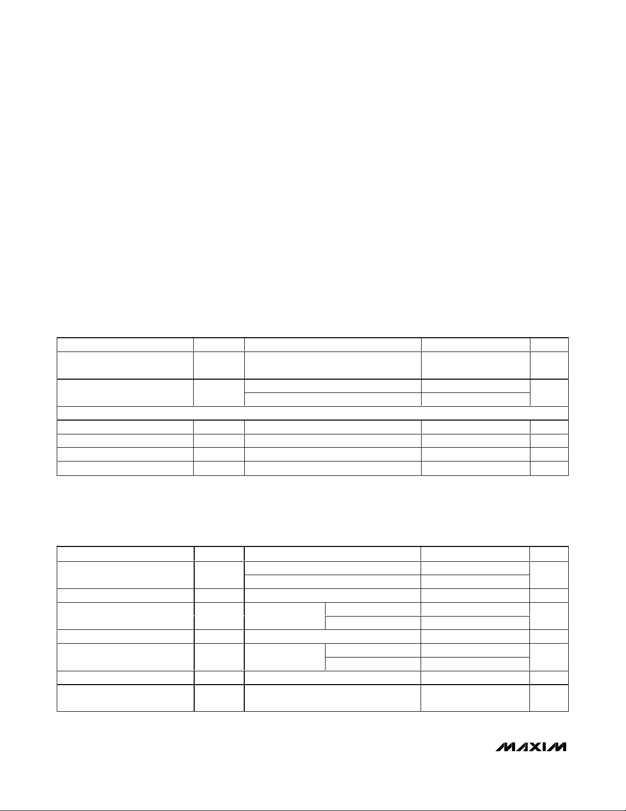
ABSOLUTE MAXIMUM RATINGS
DC ELECTRICAL CHARACTERISTICS
(MAX2058
Typical Application Circuit
, VCC= +4.75V to +5.25V, R1 = 1.2kΩ, R2 = 3.92kΩ, R3 = 2kΩ, TC= -40°C to +85°C. Typical
values are at V
CC
= +5.0V and TC= +25°C, unless otherwise noted.) (Note 1)
Stresses beyond those listed under “Absolute Maximum Ratings” may cause permanent damage to the device. These are stress ratings only, and functional
operation of the device at these or any other conditions beyond those indicated in the operational sections of the specifications is not implied. Exposure to
absolute maximum rating conditions for extended periods may affect device reliability.
V
CC
to GND ...........................................................-0.3V to +5.5V
RSET1, RSET2......................................................+1.2V to +4.0V
LBBIAS .......................................................(V
CC
- 1.5V) to +5.5V
LB_EN, DATA, CS, CLK .............................-0.3V to (V
CC
+ 0.3V)
ATTEN_INA, ATTEN_INB, ATTEN_OUTA, ATTEN_OUTB
Input Power .................................................................+24dBm
AMPIN, Differential LO Input Power ...............................+12dBm
Continuous Power Dissipation (T
A
= +70°C)
40-Pin TQFN (derated 26.3mW/°C above +70°C) ......2100mW
Operating Temperature Range (Note A) .............-40°C to +85°C
Junction Temperature......................................................+150°C
θ
JC
....................................................................................10°C/W
θ
JA
....................................................................................38°C/W
Storage Temperature Range .............................-65°C to +150°C
Lead Temperature (soldering, 10s) .................................+300°C
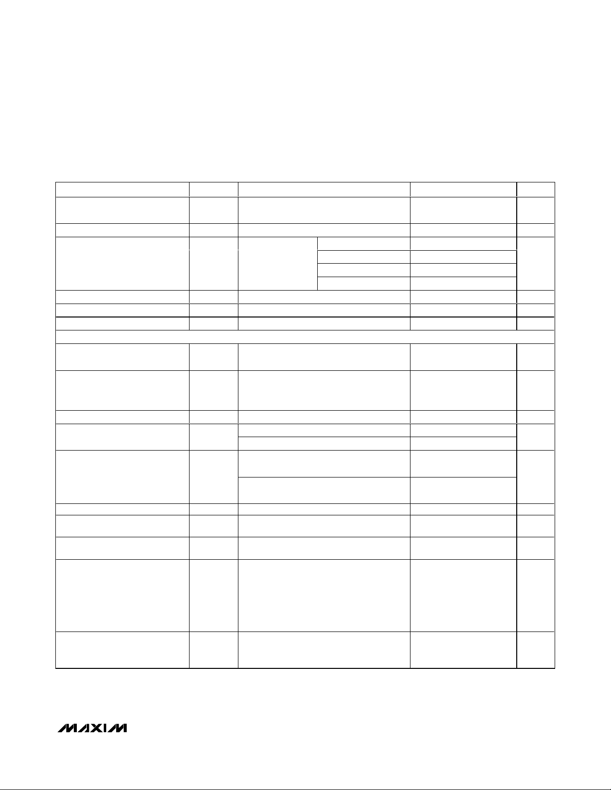
AC ELECTRICAL CHARACTERISTICS
(MAX2058
Typical Application Circuit
, VCC= +4.75V to +5.25V, digital attenuators set for maximum gain, 700MHz ≤ fRF≤ 1200MHz,
40MHz ≤ f
LO
≤ 100MHz, TC= -40°C to +85°C. Typical values are at VCC= 5.0V, PIN= 0dBm, fRF= 940MHz, PLO= -6dBm, fLO=
45MHz, f
LBOUT
= fRF- fLO, and TC= +25°C, unless otherwise noted.) (Note 1)
Note A: TCis the temperature on the exposed paddle of the package.
Supply Voltage V
Total Supply Current I
LOGIC INPUTS (DATA, CS, CLK, LB_EN)
Input High Voltage V
Input Low Voltage V
Input Current with Logic-High I
Input Current with Logic-Low I
PARAMETER SYMBOL CONDITIONS MIN TYP MAX UNITS
CC
CC
IH
IL
Reference to VCC, VCCLB, VCCLOGIC,
VCCBIAS1, VCCBIAS2, VCCAMP
LB mixer disabled (LB_EN = 1) 134 156
LB mixer enabled (LB_EN = 0) 158 186
IH
IL
4.75 5.0 5.25 V
2.4 V
0.8 V
0.01 µA
0.01 µA
mA
RF Frequency (Note 2)
Small-Signal Gain A
Gain Variation vs. Temperature
Output Power P
Output Power Flatness PIN = 0dBm
Attenuation Range 62 dB
Output Third-Order Intercept
Point
PARAMETER SYMBOL CONDITIONS MIN TYP MAX UNITS
MAX2058 700 1200
MAX2059 1800 2200
fRF = 940MHz, TC = +25°C 8.4 10.5 12.8 dB
V
-0.014
32.3 dBm
OUT
OIP3
All attenuation
settings
PIN = 0dBm, fRF = 940MHz, TC = +25°C 8.4 10.5 12.8 dBm
Two tones: f
P
OUT1
= P
RF1
OUT2
TC = -40°C to +25°C
T
= +25°C to +85°C -0.021
C
800MHz to 900MHz 0.13
900MHz to 1000MHz -0.52
= 940MHz, f
= +5dBm
= 941MHz,
RF2
MHz
dB/°C
dB
Page 3
MAX2058
700MHz to 1200MHz High-Linearity,
SPI-Controlled DVGA with Integrated Loopback Mixer
_______________________________________________________________________________________ 3
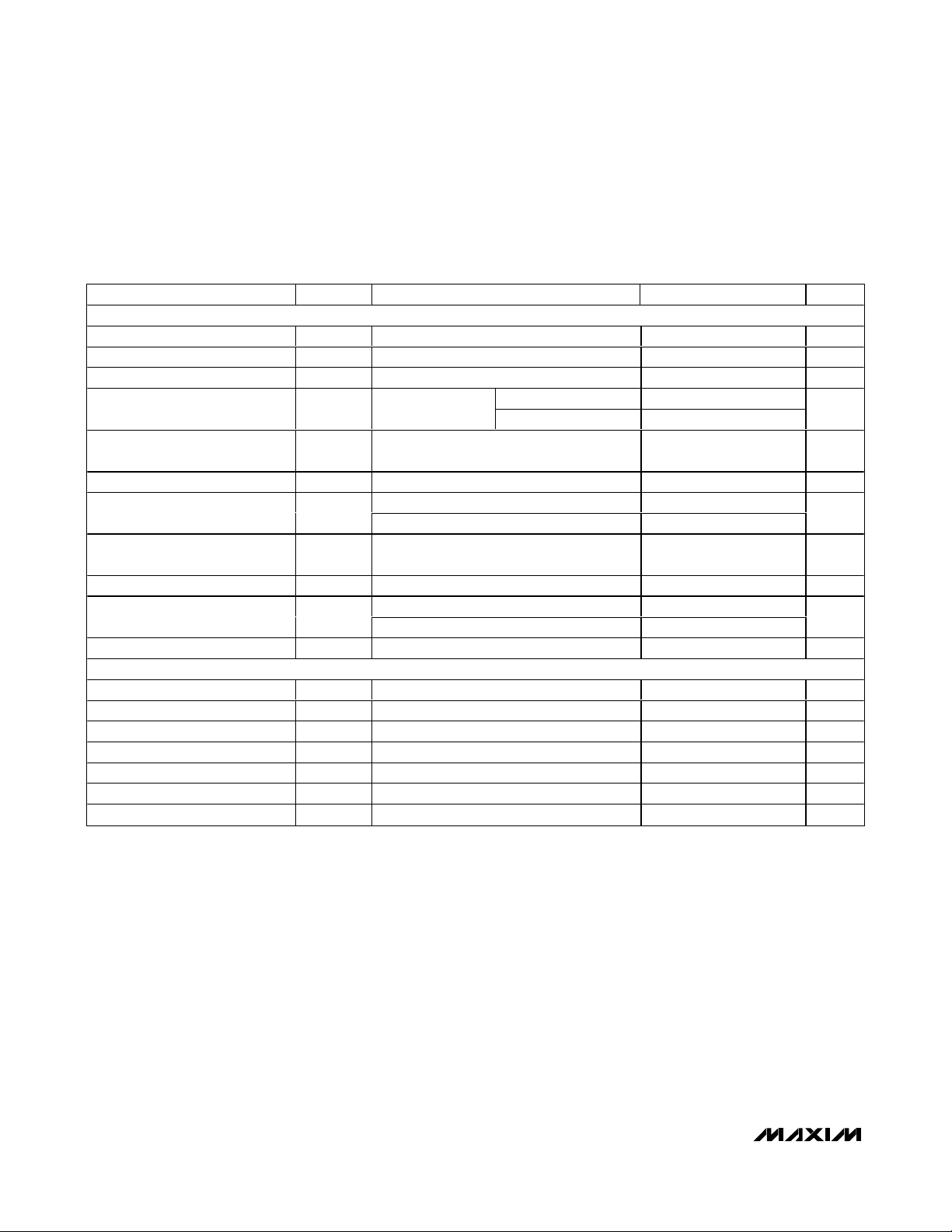
AC ELECTRICAL CHARACTERISTICS (continued)
(MAX2058
Typical Application Circuit
, VCC= +4.75V to +5.25V, digital attenuators set for maximum gain, 700MHz ≤ fRF≤ 1200MHz,
40MHz ≤ f
LO
≤ 100MHz, TC= -40°C to +85°C. Typical values are at VCC= 5.0V, PIN= 0dBm, fRF= 940MHz, PLO= -6dBm, fLO=
45MHz, f
LBOUT
= fRF- fLO, and TC= +25°C, unless otherwise noted.) (Note 1)
Output -1dB Compression Point
(Note 3)
RMS Error Vector Magnitude EVM P
Spurious Emissions in 30kHz
Bandwidth (Note 4)
Noise Figure NF 6.8 dB
Input Return Loss 50Ω source, minimum attenuation setting 18 dB
Output Return Loss 50Ω load, minimum attenuation setting 20 dB
5-BIT DIGITAL ATTENUATORS
Insertion Loss
Input Third-Order Intercept Point IIP3
Control Range 31 dB
Attenuation Step Size Variation
vs. Frequency
Attenuation Variation vs.
Temperature
Step Size 1dB
Relative Step Accuracy 800MHz to 1000MHz
Absolute Step Accuracy 800MHz to 1000MHz
Spurious Emissions in 300kHz
Bandwidth (Note 5)
PARAMETER SYMBOL CONDITIONS MIN TYP MAX UNITS
OP
1dB
= +12dBm, EDGE modulation 0.5 %
OUT
200kHz offset -39.2
P
= +12dBm,
OUT
EDGE modulation
Attenuator measured separately Z
50Ω
Attenuator measured separately Z
50Ω, two tones: f
941MHz, P
800MHz to 900MHz ±0.08
900MHz to 1000MHz ±0.06
800MHz to 1000MHz,
T
= -40°C to +25°C
C
800MHz to 1000MHz,
T
= +25°C to +85°C
C
No RF input, attenuator A stepped from 0 to
2dB, 7dB to 9dB, 15dB to 17dB, 0 to 31dB,
31dB to 0dB, with attenuator B at 0dB;
attenuator B stepped from 0 to 2dB, 7dB to
9dB, 15dB to 17dB, 0 to 31dB, 31dB to
0dB, with attenuator A at 0dB
IN1
400kHz offset -73.5
600kHz offset -82.7
1.2MHz offset -85.7
= ZL =
S
= ZL =
S
RF2
=
= P
RF1
IN2
= 940MHz, f
= +5dBm
19 dBm
3.3 dB
44 dBm
±0.002
±0.003
-0.2
+0.4
-0.2
+0.5
-85 dBm
dBc
dB
dB/°C
dB
dB
Switching Speed
From chip select transitioning high to the
output settling to within 1dB of steady state
output
0.3 µs
Page 4
MAX2058
700MHz to 1200MHz High-Linearity,
SPI-Controlled DVGA with Integrated Loopback Mixer
4 _______________________________________________________________________________________
AC ELECTRICAL CHARACTERISTICS (continued)
(MAX2058
Typical Application Circuit
, VCC= +4.75V to +5.25V, digital attenuators set for maximum gain, 700MHz ≤ fRF≤ 1200MHz,
40MHz ≤ f
LO
≤ 100MHz, TC= -40°C to +85°C. Typical values are at VCC= 5.0V, PIN= 0dBm, fRF= 940MHz, PLO= -6dBm, fLO=
45MHz, f
LBOUT
= fRF- fLO, and TC= +25°C, unless otherwise noted.) (Note 1)
Note 1: All limits include external component losses. Output measurements taken at RFOUT or LBOUT ports of the
Typical
Application Circuit
.
Note 2: Operating outside this range is possible, but with degraded performance of some parameters.
Note 3: Compression point characterized. It is advisable not to continuously operate the VGA RF input above +15dBm.
Note 4: Input RF source contribution to spurious emissions (Agilent ESG 4435B, PSA E4443A): 200kHz = -39.2dBc,
400kHz = -73.5dBc, 600kHz = -83.2dBc, 1.2MHz = -85.7dBc
Note 5: No SPI clock input applied.
Note 6: Guaranteed by design and characterization.
LOOPBACK MIXER
LO Frequency (Note 2) f
LO Input Power P
Output Power (Note 6) PIN = +5dBm, fRF = 940MHz, TC = +25°C -14.7 -12.7 -10.8 dBm
Gain Accuracy
Output Third-Order Intercept
Point (Note 6)
Output Noise Floor PIN = +5dBm -137 dBc/Hz
ON/OFF Switching Time
LBOUT to ATTEN_OUTB Isolation
ATTEN_OUTB to LBOUT Isolation Mixer disabled, PIN = 0dBm 50 dB
Output Return Loss
LO Port Return Loss 50Ω source 32 dB
SERIAL PERIPHERAL INTERFACE (SPI)
Maximum Clock Speed 38 MHz
Data to Clock Setup Time t
Data to Clock Hold Time t
Clock to CS Setup Time t
CS Positive Pulse Width t
CS Negative Pulse Width t
CLOCK Pulse Width t
PARAMETER SYMBOL CONDITIONS MIN TYP MAX UNITS
LO
LO
OIP3
CS
CH
ES
EW
EWN
CW
P
= +5dBm, T
IN
= -40°C to +25°C
Tw o tones: f
P
IN 1
LB_EN enable time 0.12
LB_EN disable time 0.12
Mixer enabled, attenuators A and B both set
to 31dB, P
Mixer enabled, 50Ω load 22
Mixer disabled, 50Ω load 23
R F1
= P
= + 2d Bm , TC = + 25°C
IN 2
= +5dBm
IN
800MHz to 900MHz ±1.7
C
900MHz to 1000MHz ±1.7
= 940M H z, f
= 940.2M H z,
R F2
40 100 MHz
-6 0 dBm
10.6 dBm
67 dB
1ns
9ns
4ns
18 ns
24 ns
13 ns
dB
µs
dB
Page 5
MAX2058
700MHz to 1200MHz High-Linearity,
SPI-Controlled DVGA with Integrated Loopback Mixer
_______________________________________________________________________________________
5
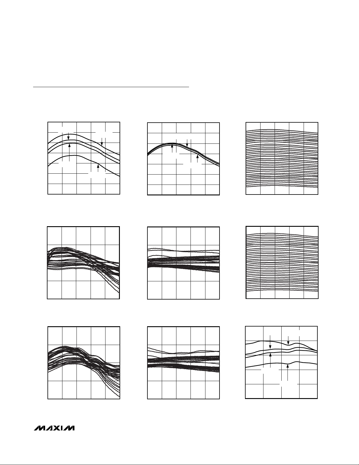
Typical Operating Characteristics
(MAX2058
Typical Application Circuit
, VCC= +4.75V to +5.25V, digital attenuators set for maximum gain, 700MHz ≤ fRF≤ 1200MHz,
40MHz ≤ f
LO
≤ 100MHz, TC= -40°C to +85°C. Typical values are at VCC= 5.0V, PIN= 0dBm, fRF= 940MHz, fLO= 45MHz, f
LBOUT
=
fRF- fLO, and TC= +25°C, unless otherwise noted.)
GAIN vs. RF FREQUENCY
(MAXIMUM GAIN)
13
12
11
10
GAIN (dB)
TC = +5°C
9
TC = +25°C
8
7
6
700 800 900 1000 1100 1200
RF FREQUENCY (MHz)
TC = -40°C
TC = +85°C
MAX2058 toc01
GAIN (dB)
ATTEN A ABS ACCURACY vs. RF FREQUENCY
1.0
0.5
MAX2058 toc04
GAIN vs. RF FREQUENCY
(MAXIMUM GAIN)
13
12
11
10
9
8
7
6
700 900800 1000 1100 1200
ATTEN A REL ACCURACY vs. RF FREQUENCY
1.0
0.5
VCC = 5.25V
VCC = 5.0V
VCC = 4.75V
RF FREQUENCY (MHz)
MAX2058 toc02
MAX2058 toc05
GAIN vs. RF FREQUENCY
ADJUSTING ATTEN A
15
5
-5
GAIN (dB)
-15
-25
700 800 900 1000 1100 1200
RF FREQUENCY (MHz)
GAIN vs. RF FREQUENCY
ADJUSTING ATTEN B
15
5
MAX2058 toc03
MAX2058 toc06
0
ERROR (dB)
-0.5
-1.0
700 800 900 1000 1100 1200
RF FREQUENCY (MHz)
ATTEN B ABS ACCURACY vs. RF FREQUENCY
1.0
0.5
0
ERROR (dB)
-0.5
-1.0
700 800 900 1000 1100 1200
RF FREQUENCY (MHz)
MAX2058 toc07
0
ERROR (dB)
-0.5
-1.0
700 800 900 1000 1100 1200
RF FREQUENCY (MHz)
ATTEN B REL ACCURACY vs. RF FREQUENCY
1.0
0.5
0
ERROR (dB)
-0.5
-1.0
700 800 900 1000 1100 1200
RF FREQUENCY (MHz)
MAX2058 toc08
-5
GAIN (dB)
-15
-25
700 800 900 1000 1100 1200
RF FREQUENCY (MHz)
OUTPUT IP3 vs. RF FREQUENCY
34
TC = +5°C
33
32
31
OUTPUT IP3 (dBm)
30
29
800 850 900 950 1000
TC = +25°C
RF FREQUENCY (MHz)
TC = -40°C
TC = +85°C
MAX2058 toc09
Page 6

MAX2058
700MHz to 1200MHz High-Linearity,
SPI-Controlled DVGA with Integrated Loopback Mixer
6 _______________________________________________________________________________________
Typical Operating Characteristics (continued)
(MAX2058
Typical Application Circuit
, VCC= +4.75V to +5.25V, digital attenuators set for maximum gain, 700MHz ≤ fRF≤ 1200MHz,
40MHz ≤ f
LO
≤ 100MHz, TC= -40°C to +85°C. Typical values are at VCC= 5.0V, PIN= 0dBm, fRF= 940MHz, fLO= 45MHz, f
LBOUT
=
fRF- fLO, and TC= +25°C, unless otherwise noted.)
OUTPUT IP3 vs. RF FREQUENCY
34
VCC = 5.25V
33
32
31
OUTPUT IP3 (dBm)
30
29
800 850 900 950 1000
22
21
20
19
(dBm)
1dB
18
17
OUTPUT P
16
15
14
700 800 900 1000 1100 1200
VCC = 5.0V
OUTPUT P
TC = -40°C
TC = +85°C
VCC = 4.75V
RF FREQUENCY (MHz)
vs. RF FREQUENCY
1dB
TC = +5°C
TC = +25°C
RF FREQUENCY (MHz)
NOISE FIGURE vs. RF FREQUENCY
10
9
8
7
6
NOISE FIGURE (dB)
5
4
700 800 900 1000 1100 1200
VCC = 5.0V
VCC = 4.75V
RF FREQUENCY (MHz)
MAX2058 toc10
NOISE FIGURE vs. RF FREQUENCY
10
9
8
7
6
NOISE FIGURE (dB)
5
4
TC = +85°C
TC = +25°C
TC = +5°C
TC = -40°C
700 800 900 1000 1100 1200
RF FREQUENCY (MHz)
MAX2058 toc11
INPUT RETURN LOSS vs. RF FREQUENCY
MAX2058 toc13
OUTPUT P
22
21
VCC = 5.25V
20
19
(dBm)
1dB
18
17
OUTPUT P
16
15
14
VCC = 4.75V
700 800 900 1000 1100 1200
vs. RF FREQUENCY
1dB
VCC = 5.0V
RF FREQUENCY (MHz)
0
MAX2058 toc14
5
10
15
20
INPUT RETURN LOSS (dB)
25
30
ATTEN A VARIED
0dB
16dB, 31dB
700 800 900 1000 1100 1200
RF FREQUENCY (MHz)
2dB
8dB
4dB
1dB
VCC = 5.25V
MAX2058 toc12
MAX2058 toc15
INPUT RETURN LOSS vs. RF FREQUENCY
ATTEN B VARIED
0
5
10
15
20
INPUT RETURN LOSS (dB)
25
30
700 800 900 1000 1100 1200
31dB
0dB, 1dB
RF FREQUENCY (MHz)
MAX2058 toc16
OUTPUT RETURN LOSS vs. RF FREQUENCY
ATTEN A VARIED
0
10
31dB
20
30
OUTPUT RETURN LOSS (dB)
40
700 800 900 1000 1100 1200
0dB
RF FREQUENCY (MHz)
OUTPUT RETURN LOSS vs. RF FREQUENCY
0
MAX2058 toc17
10
20
30
OUTPUT RETURN LOSS (dB)
40
700 800 900 1000 1100 1200
ATTEN B VARIED
4dB
1dB
RF FREQUENCY (MHz)
2dB
0dB
16dB, 31dB
8dB
MAX2058 toc18
Page 7

MAX2058
700MHz to 1200MHz High-Linearity,
SPI-Controlled DVGA with Integrated Loopback Mixer
_______________________________________________________________________________________
7
Typical Operating Characteristics (continued)
(MAX2058
Typical Application Circuit
, VCC= +4.75V to +5.25V, digital attenuators set for maximum gain, 700MHz ≤ fRF≤ 1200MHz,
40MHz ≤ f
LO
≤ 100MHz, TC= -40°C to +85°C. Typical values are at VCC= 5.0V, PIN= 0dBm, fRF= 940MHz, fLO= 45MHz, f
LBOUT
=
fRF- fLO, and TC= +25°C, unless otherwise noted.)
GAIN (dB)
CONVERSION LOSS (dB)
REVERSE GAIN vs. RF FREQUENCY
ADJUSTING ATTEN A AND B
-30
-40
ATTEN A AND B, 0dB
-50
-60
-70
-80
700 800 900 1000 1100 1200
ATTEN A, 31dB
ATTEN B, 31dB
RF FREQUENCY (MHz)
MIXER CONV LOSS vs. RF FREQUENCY
20
19
18
17
16
15
PLO = -6dBm
PLO = -3dBm
PLO = 0dBm
20
19
MAX2058 toc19
18
17
16
CONVERSION LOSS (dB)
15
14
13
12
MAX2058 toc22
11
10
OUTPUT IP3 (dBm)
MIXER CONV LOSS vs. RF FREQUENCY
TC = +85°C
TC = +5°C
800 850 900 950 1000
RF FREQUENCY (MHz)
TC = +25°C
TC = -40°C
MIXER OUTPUT IP3 vs. RF FREQUENCY
TC = +5°C
9
TC = +25°C
8
TC = -40°C
TC = +85°C
20
19
MAX2058 toc20
18
17
16
CONVERSION LOSS (dB)
15
14
13
12
MAX2058 toc23
11
10
OUTPUT IP3 (dBm)
MIXER CONV LOSS vs. RF FREQUENCY
VCC = 4.75V
VCC = 5.0V
800 850 900 950 1000
RF FREQUENCY (MHz)
VCC = 5.25V
MIXER OUTPUT IP3 vs. RF FREQUENCY
VCC = 5.25V
VCC = 4.75V
9
8
VCC = 5.0V
MAX2058 toc21
MAX2058 toc24
14
800 850 900 950 1000
RF FREQUENCY (MHz)
MIXER OUTPUT IP3 vs. RF FREQUENCY
13
12
11
10
9
OUTPUT IP3 (dBm)
8
7
800 850 900 950 1000
PLO = -3dBm, 0dBm
PLO = -6dBm
RF FREQUENCY (MHz)
PLO = 0dBm
7
800 850 900 950 1000
vs. RF FREQUENCY (MIXER ENABLED)
0
MAX2058 toc25
10
20
30
MIXER OUT RETURN LOSS (dB)
40
700 800 900 1000 1100 1200
RF FREQUENCY (MHz)
MIXER OUTPUT RETURN LOSS
TC = +5°C
TC = +85°C
RF FREQUENCY (MHz)
TC = -40°C
TC = +25°C
7
800 850 900 950 1000
vs. RF FREQUENCY (MIXER ENABLED)
0
MAX2058 toc26
10
20
30
MIXER OUT RETURN LOSS (dB)
40
700 800 900 1000 1100 1200
RF FREQUENCY (MHz)
MIXER OUTPUT RETURN LOSS
MAX2058 toc27
VCC = 4.75V, 5.0V, 5.25V
RF FREQUENCY (MHz)
Page 8

MAX2058
700MHz to 1200MHz High-Linearity,
SPI-Controlled DVGA with Integrated Loopback Mixer
8 _______________________________________________________________________________________
Typical Operating Characteristics (continued)
(MAX2058
Typical Application Circuit
, VCC= +4.75V to +5.25V, digital attenuators set for maximum gain, 700MHz ≤ fRF≤ 1200MHz,
40MHz ≤ f
LO
≤ 100MHz, TC= -40°C to +85°C. Typical values are at VCC= 5.0V, PIN= 0dBm, fRF= 940MHz, fLO= 45MHz, f
LBOUT
=
fRF- fLO, and TC= +25°C, unless otherwise noted.)
MIXER OUTPUT RETURN LOSS
vs. RF FREQUENCY (MIXER DISABLED)
0
MIXER OUTPUT RETURN LOSS
vs. RF FREQUENCY (MIXER DISABLED)
0
LO RETURN LOSS vs. LO FREQUENCY
(MIXER ENABLED)
0
10
TC = +5°C
20
30
MIXER OUT RETURN LOSS (dB)
TC = +85°C
40
700 800 900 1000 1100 1200
RF FREQUENCY (MHz)
LO RETURN LOSS vs. LO FREQUENCY
0
10
20
LO RETURN LOSS (dB)
30
40
0 200
(MIXER ENABLED)
VCC = 4.75V, 5.0V, 5.25V
LO FREQUENCY (MHz)
ATTEN A ONLY
ABS ACCURACY vs. RF FREQUENCY
2.0
1.5
1.0
0.5
0
ERROR (dB)
-0.5
-1.0
-1.5
-2.0
RF FREQUENCY (MHz)
TC = -40°C
TC = +25°C
MAX2058 toc28
10
20
30
MIXER OUT RETURN LOSS (dB)
40
700 800 900 1000 1100 1200
VCC = 4.75V, 5.0V, 5.25V
RF FREQUENCY (MHz)
MAX2058 toc29
10
20
LO RETURN LOSS (dB)
30
40
TC = +85°C
TC = +25°C
TC = -40°C
TC = +5°C
0 50 100 150 200
LO FREQUENCY (MHz)
MAX2058 toc30
ATTEN A ONLY
ATTEN A ONLY
0
MAX2058 toc31
-10
-20
GAIN (dB)
-30
15010050
-40
GAIN vs. RF FREQUENCY
700 1200
RF FREQUENCY (MHz)
1000 1100900800
MAX2058 toc32
-10
-20
GAIN (dB)
-30
-40
GAIN vs. RF FREQUENCY
0
300
(NMT 450MHz BAND)
MAX2058 toc33
500 550350 400 450
RF FREQUENCY (MHz)
ATTEN A ONLY
ABS ACCURACY vs. RF FREQUENCY
2.0
1.5
MAX2058 toc34
1.0
0.5
0
ERROR (dB)
-0.5
-1.0
-1.5
-2.0
11001000900800700
1200
300
(NMT 450MHz BAND)
MAX2058 toc35
550500450400350
RF FREQUENCY (MHz)
REL ACCURACY vs. RF FREQUENCY
1.0
0.5
0
ERROR (dB)
-0.5
-1.0
ATTEN A ONLY
1000900700 800
RF FREQUENCY (MHz)
MAX2058 toc36
12001100
Page 9

MAX2058
700MHz to 1200MHz High-Linearity,
SPI-Controlled DVGA with Integrated Loopback Mixer
_______________________________________________________________________________________ 9
Typical Operating Characteristics (continued)
(MAX2058
Typical Application Circuit
, VCC= +4.75V to +5.25V, digital attenuators set for maximum gain, 700MHz ≤ fRF≤ 1200MHz,
40MHz ≤ f
LO
≤ 100MHz, TC= -40°C to +85°C. Typical values are at VCC= 5.0V, PIN= 0dBm, fRF= 940MHz, fLO= 45MHz, f
LBOUT
=
fRF- fLO, and TC= +25°C, unless otherwise noted.)
ATTEN A ONLY
REL ACCURACY vs. RF FREQUENCY
1.0
0.5
0
ERROR (dB)
-0.5
-1.0
(NMT 450MHz BAND)
RF FREQUENCY (MHz)
2.0
1.5
1.0
0.5
0
ERROR (dB)
-0.5
-1.0
-1.5
-2.0
MAX2058 toc37
-10
-20
GAIN (dB)
-30
500450400350300
550
-40
ATTEN B ONLY
ABS ACCURACY vs. RF FREQUENCY
RF FREQUENCY (MHz)
ATTEN B ONLY
0
GAIN vs. RF FREQUENCY
700 1200
RF FREQUENCY (MHz)
1000 1100900800
ABS ACCURACY vs. RF FREQUENCY
2.0
MAX2058 toc40
11001000900800700
1200
1.5
1.0
0.5
0
ERROR (dB)
-0.5
-1.0
-1.5
-2.0
300
0
MAX2058 toc38
-10
-20
GAIN (dB)
-30
-40
300
ATTEN B ONLY
(NMT 450MHz BAND)
RF FREQUENCY (MHz)
ATTEN B ONLY
GAIN vs. RF FREQUENCY
(NMT 450MHz BAND)
RF FREQUENCY (MHz)
MAX2058 toc41
550500450400350
500 550350 400 450
MAX2058 toc39
Page 10

MAX2058
700MHz to 1200MHz High-Linearity,
SPI-Controlled DVGA with Integrated Loopback Mixer
10 ______________________________________________________________________________________
Typical Operating Characteristics (continued)
(MAX2058
Typical Application Circuit
, VCC= +4.75V to +5.25V, digital attenuators set for maximum gain, 700MHz ≤ fRF≤ 1200MHz,
40MHz ≤ f
LO
≤ 100MHz, TC= -40°C to +85°C. Typical values are at VCC= 5.0V, PIN= 0dBm, fRF= 940MHz, fLO= 45MHz, f
LBOUT
=
f
RF
- fLO, and TC= +25°C, unless otherwise noted.)
ATTEN B ONLY
REL ACCURACY vs. RF FREQUENCY
MAX2058 toc42
RF FREQUENCY (MHz)
ERROR (dB)
1000900700 800
-0.5
0
0.5
1.0
-1.0
12001100
ATTEN B ONLY
REL ACCURACY vs. RF FREQUENCY
(NMT 450MHz BAND)
MAX2058 toc43
RF FREQUENCY (MHz)
ERROR (dB)
500450400350300
-0.5
0
0.5
1.0
-1.0
550
SUPPLY CURRENT vs. SUPPLY VOLTAGE
(MIXER DISABLED)
VCC (V)
SUPPLY CURRENT (mA)
MAX2058 toc44
4.750 4.875 5.000 5.125 5.250
110
120
130
140
150
TC = +25°C
TC = +5°C
TC = -40°C
TC = +85°C
SUPPLY CURRENT vs. SUPPLY VOLTAGE
(MIXER ENABLED)
VCC (V)
SUPPLY CURRENT (mA)
MAX2058 toc45
4.750 4.875 5.000 5.125 5.250
130
140
150
160
170
180
TC = +85°C
TC = +5°C
TC = -40°C
TC = +25°C
Page 11

MAX2058
Pin Description
700MHz to 1200MHz High-Linearity,
SPI-Controlled DVGA with Integrated Loopback Mixer
______________________________________________________________________________________ 11
PIN NAME FUNCTION
1 LO+ Loopback Mixer Local Oscillator Positive Input
2 LO- Loopback Mixer Local Oscillator Negative Input
3 VCCLB
4 LBOUT Loopback Mixer RF Output. Internally matched to 50Ω. AC-couple with a capacitor.
5 LB_EN Loop b ack M i xer Log i c Inp ut. S et to l og i c- l ow 0 to enab l e the m i xer . S et to l og i c- hi g h 1 to d i sab l e the m i xer .
6 DATA SPI Digital Data Input
7 CLK SPI Clock Input
8 CS SPI Chip-Select Input
9 VCCLOGIC
10, 11, 13,
14, 16, 17,
19, 22, 24,
25, 26, 30,
32, 34, 35,
37, 38
12 ATTEN_OUTB Attenuator B Output. Internally matched to 50Ω.
15 V
18 ATTEN_INB Attenuator B Input. Internally matched to 50Ω.
20 RSET2
21 VCCBIAS2
23 AMPOUT RF Amplifier Output. Internally matched to 50Ω.
27 VCCAMP
28 AMPIN RF Amplifier Input. Internally matched to 50Ω.
29 VCCBIAS1
31 RSET1
33 ATTEN_OUTA Attenuator A Output. Internally matched to 50Ω.
36 V
39 ATTEN_INA Attenuator A Input. Internally matched to 50Ω.
40 LBBIAS
EP GND Exposed Ground Paddle. Solder the exposed paddle to GND using multiple vias.
GND Ground
CC
CC
Loopback Mixer Supply Voltage. +5V supply for the internal loopback mixer. Bypass to GND with
100pF and 0.1µF capacitors as close as possible to the pin.
Logic Supply Voltage. +5V supply for the internal logic circuitry. Bypass to GND with 100pF and
0.1µF capacitors as close as possible to the pin.
Attenuator B Supply. +5V supply for attenuator B. Bypass to GND with 100pF and 0.01µF capacitors
as close as possible to the pin.
Output Amplifier Bias-Current-Setting Resistor. Sets the bias current for the output amplifier stage.
Connect a 3.92kΩ resistor to ground.
Bias Circuit Supply Voltage. +5V supply for the internal bias circuitry. Bypass to GND with 1000pF
and 0.1µF capacitors as close as possible to the pin.
RF Amplifier Supply Voltage. +5V supply for the RF amplifier. Bypass to GND with 1000pF and 0.1µF
capacitors as close as possible to the pin.
Bias Circuit Supply Voltage. +5V supply for the internal bias circuitry. Bypass to GND with 1000pF
and 0.1µF capacitors as close as possible to the pin.
Input Amplifier Bias-Current-Setting Resistor. Sets the bias current for the input amplifier stage.
Connect a 1.2kΩ resistor to ground.
Attenuator A Supply Voltage. +5V supply for attenuator A. Bypass to GND with 100pF and 0.01µF
capacitors as close as possible to the pin.
Loopback Mixer Bias-Current-Setting Resistor. Sets the bias current for the mixer. Connect a 2kΩ
resistor to ground.
Page 12

MAX2058
700MHz to 1200MHz High-Linearity,
SPI-Controlled DVGA with Integrated Loopback Mixer
12 ______________________________________________________________________________________
Detailed Description
The MAX2058 high-linearity DVGA consists of two 5-bit,
31dB digital attenuators, a fixed-gain two-stage driver
amplifier, a loopback mixer, and a serial interface to
control the attenuators. This high level of component
integration makes the MAX2058 ideal for base-station
transmitter applications. The MAX2058 is designed to
operate in the 700MHz to 1200MHz frequency ranges.
The overall cascaded performance of the MAX2058
produces a typical 10.5dB gain, a +32.3dBm OIP3, a
19dBm OP1dB, and a total 62dB gain-control range.
5-Bit Attenuators
The MAX2058 integrates two 5-bit digital attenuators to
achieve a high dynamic range. Each attenuator has a
31dB control range, a 1dB step size, and is programmed with the 3-wire SPI. See the
Applications
Information
section and Table 1 for attenuator programming details. The attenuators can be used for both static and dynamic power control.
Driver Amplifier
The MAX2058 includes a two-stage medium power
amplifier with a fixed 17.5dB gain. The driver amplifier
circuit is optimized for high linearity and medium output
power capability for the 800MHz to 1000MHz frequency range. The driver amplifier is intended to amplify a
modulated signal and drive a high-power amplifier in
base-station transmitters. In a typical application, the
driver amplifier is cascaded in between the two digital
attenuators. See the
Typical Application Circuit.
The two-stage amplifier stage can be disabled for
applications where only the digital attenuators and/or
loopback mixer are used. To disable the two-stage
amplifier, ground or leave unconnected the amplifier
supplies VCCBIAS2, VCCAMP, VCCBIAS1, and also
the inputs for setting the amplifier bias currents RSET1,
RSET2. This reduces the supply current by approximately 132mA under typical conditions.
Loopback Mixer
The MAX2058 loopback mixer uses a double-balanced
active architecture designed to operate with a 700MHz
to 1200MHz RF frequency range, and a 40MHz to
100MHz LO frequency range. The RF port of the mixer is
connected internally (with an on-chip switch) to the input
of the first attenuator stage. The mixer’s IF port is
matched for a single-ended 50Ω impedance, while the
LO port requires a differential input impedance of 100Ω.
The loopback mixer facilitates a self-diagnostic mode
for cellular transceivers, whereby the Tx band signal at
the input of the mixer can be translated up or down to
the corresponding Rx band. This translated signal can
then be fed back to the radio’s receiver for complete
Tx/Rx loop diagnostics. The loopback mixer is enabled
and disabled with LB_EN. Set LB_EN to a logic-low 0 to
enable the mixer, set LB_EN to a logic-high 1 to disable
the mixer.
Applications Information
SPI Interface and Attenuator Settings
The two 5-bit attenuators are programmed with the 3wire SPI/MICROWIRE-compatible serial interface using
10-bit words. Bit 9 of the 10-bit data is shifted in first,
along with all remaining data bits, on the rising edge of
the clock regardless of CS being high or low. Once all
the data bits are shifted in, all will be sent to the attenuators on the rising edge of CS, thus changing the attenuation state. For standard SPI operation, pull CS low for the
duration of a valid 10-bit data set (t
EWN
). This CS nega-
tive pulse width includes the setup time of the rising
clock edge to CS transitioning high (tES). See Figure 1.
Table 1. Attenuator Programming
Figure 1. SPI Timing Diagram
ATTENUATOR A (5 MSBs) ATTENUATOR B (5 LSBs)
Bit 9 = 16dB step Bit 4 = 16dB step
Bit 8 = 8dB step Bit 3 = 8dB step
Bit 7 = 4dB step Bit 2 = 4dB step
Bit 6 = 2dB step Bit 1 = 2dB step
Bit 5 = 1dB step Bit 0 = 1dB step
MSBDATA
BIT 9 BIT 8 BIT 1 BIT 0 LSB
CLOCK
CS
NOTES:
DATA ENTERED ON CLOCK RISING EDGE.
ATTENUATOR STATE CHANGE ON CS RISING EDGE.
t
CS
t
t
CH
CW
t
EWN
t
ES
t
EW
Page 13

MAX2058
700MHz to 1200MHz High-Linearity,
SPI-Controlled DVGA with Integrated Loopback Mixer
______________________________________________________________________________________ 13
Figure 2. Direct Conversion Transmitter for GSM/EDGE Basestations
The 5 MSBs of the 10-bit word program attenuator A,
and the 5 LSBs of the 10-bit word program attenuator
B. Each bit sets the attenuators to a corresponding
attenuation level. For example, logic-low 0 for bit 5 and
bit 0 of attenuator A and B, respectively, sets both
attenuators at 1dB. 00000 configures both attenuators
for 31dB attenuation and 11111 sets for 0dB attenuation. See Table 1 for programming details.
External Bias
Bias currents for the two-stage amplifier and the loopback mixer are set and optimized with external resistors.
Resistor R1 (pin 31) sets the bias current for the input
amplifier, R2 (pin 20) sets the bias current for the output
amplifier, and R3 (pin 40) sets the bias for the loopback
mixer. The external biasing resistor values can be
increased for reduced current operation at the expense
of performance. Contact the factory for details.
Board Layout
The pin configuration of the MAX2058 has been optimized to facilitate a very compact physical layout of the
device and its associated discrete components.
The exposed paddle (EP) of the MAX2058’s thin QFNEP package provides a low thermal-resistance path to
the die. It is important that the PC board on which the
MAX2058 is mounted be designed to conduct heat
from the EP. In addition, provide the EP with a lowinductance path to electrical ground. The EP MUST be
soldered to a ground plane on the PC board, either
directly or through an array of plated via holes.
Table 2. Component List Referring to the
Typical Application Circuit
COMPONENT VALUE DESCRIPTION
C1, C4, C10, C13,
C16
C2, C5, C8, C17 100pF Microwave capacitors (0402)
C3, C6, C14, C19 47pF Microwave capacitors (0402)
C7, C18 0.01µF Microwave capacitors (0402)
C9, C12, C15 1000pF Microwave capacitors (0402)
C11 3.9pF Microwave capacitor (0402)
R1 1.2kΩ
R2 3.92kΩ
R3 2.0kΩ ±1% resistor (0402)
R4 110Ω ±1% resistor (0402)
T1 2:1
U1 —
0.1µF Microwave capacitors (0603)
±1% resistor (0402)
±1% resistor (0402)
RF transformer (100:50)
Mini-Circuits TC2-1T
MAX2058 MAXIM IC
MAX2021/MAX2022/MAX2023*
MAX5873 MAX4395
DUAL DAC QUAD AMP
I
12
Q
12
*FUTURE PRODUCTS—CONTACT FACTORY FOR SAMPLES
ZERO-IF
MODS/DEMODS
0°
90°
∑
MAX9491*
VCO + PLL
45, 80,
OR
95MHz
LO
MAX2058/MAX2059*
RF DIGITAL VGAs
17.5dB31dB
LOOPBACK
OUT
(FEEDS BACK
INTO Rx CHAIN
FRONT-END)
Rx
OFF
31dB
RF OUT
SPI
LOGIC
SPI
CONTROL
Page 14

MAX2058
700MHz to 1200MHz High-Linearity,
SPI-Controlled DVGA with Integrated Loopback Mixer
14 ______________________________________________________________________________________
Typical Application Circuit
Direct-Conversion Base-Station
Transmitter
The MAX2058/MAX2059 are designed to interface
directly with Maxim’s direct-conversion quadrature
modulators and high-speed DACs to provide a complete solution for GSM/EDGE base-station transmitter
applications. See Figure 2. The MAX2058/MAX2059,
together with the MAX2021/MAX2022/MAX2023* directconversion modulators/demodulators, the MAX5873
dual-channel DAC, and the MAX4395 quad amplifier,
form an ideal total transmitter lineup. This overall system is highly efficient and low cost, while maintaining
high linearity and low noise performance.
RF INPUT
C19
R3
ATTN_INA
LBBIAS
40 39 38 37
1
2
3
4
5
6
7
8
9
10
GND
C6
SPI
ATTEN_OUTB
LO INPUT
LBOUT
T1
V
CC
C1 C2
V
CC
C4 C5
R4
C3
LO+
LO-
VCCLB
LBOUT
LB_EN
DATA
CLK
CS
VCCLOGIC
GND
RF OUTPUT
GND
GND
5-BIT ATTENUATOR
5-BIT ATTENUATOR
GND
GND
V
CC
C17 C18
R1
CC
V
GND
GND
36 35 34 33 32 31
A
MAX2058
DRIVER AMP
B
15 16 17 18 19 2011 12 13 14
CC
V
GND
GND
C8
C7
GND
ATTEN_OUTA
GND
ATTEN_INB
E.P.
RSET1
RSET2
30
29
28
27
26
25
24
23
22
21
R2
GND
VCCBIAS1
AMPIN
VCCAMP
GND
GND
GND
AMPOUT
GND
VCCBIAS2
C9
C14
C13C12
C10
C11
V
CC
C16C15
V
CC
V
CC
Page 15

MAX2058
700MHz to 1200MHz High-Linearity,
SPI-Controlled DVGA with Integrated Loopback Mixer
Maxim cannot assume responsibility for use of any circuitry other than circuitry entirely embodied in a Maxim product. No circuit patent licenses are
implied. Maxim reserves the right to change the circuitry and specifications without notice at any time.
Maxim Integrated Products, 120 San Gabriel Drive, Sunnyvale, CA 94086 408-737-7600 ____________________
15
© 2006 Maxim Integrated Products is a registered trademark of Maxim Integrated Products, Inc.
Package Information
For the latest package outline information, go to
www.maxim-ic.com/packages
.
MAX2058
30
29
28
27
26
36 35 34 33 32 31
40 39 38 37
15 16 17 18 19 2011 12 13 14
25
23
21
24
22
5
4
3
2
9
8
10
7
6
1
DRIVER AMP
5-BIT ATTENUATOR
B
SPI
5-BIT ATTENUATOR
A
GND
GND
GND
GND
GND
AMPOUT
V
CC
GND
GND
GND
GND
GND
RSET1
ATTEN_OUTB
ATTEN_INB
ATTEN_INA
ATTEN_OUTA
LBBIAS
LO+
LO-
VCCLB
VCCLOGIC
VCCBIAS2
LBOUT
LB_EN
DATA
CLK
CS
GND
GND
GND
RSET2
GND
GND
GND
GND
V
CC
VCCAMP
AMPIN
VCCBIAS1
Pin Configuration/Functional Diagram
Chip Information
PROCESS: SiGe BiCMOS
 Loading...