

General Description
The MAX1736 is a simple, low-cost, single-cell lithiumion (Li+) battery charger for small hand-held applications. When accompanied by a current-limited voltage
source (such as a wall cube), the MAX1736 provides
simple, accurate charging and termination control for
single-cell Li+ batteries. The MAX1736EUT42 is preset
to a 4.2V battery regulation voltage, while the
MAX1736EUT41 is preset to 4.1V.
The MAX1736 initiates charging in one of four ways:
battery insertion, charger power-up, battery voltage
threshold, and by external manipulation of the EN pin.
The device features an internal precharge current
source that safely charges near-dead cells, as well as
input-supply detection that shuts down the MAX1736
when the supply is removed to minimize battery current
drain.
The MAX1736 accepts input voltages up to 22V, making it compatible with a wide range of input supplies. It
has a single control input yet offers stand-alone and
microprocessor-controlled operation. The MAX1736 is
packaged in a small SOT23-6 package. An evaluation
kit (EV kit) is available to reduce design time.
________________________Applications
Single-Cell Li+ Portable Applications
Wireless Handsets
Personal Digital Assistants
Digital Cameras
Small Hand-Held Equipment
Self-Charging Battery Packs
Cradle Chargers
Features
♦ Small 6-Pin SOT23 Package
♦ Stand-Alone or µP-Controlled Operation
♦ 0.5% Voltage Set-Point Accuracy
♦ Lowest Power Dissipation
♦ Low 4.7V min Input Voltage
♦ Top-Off Charging to Achieve Full Battery Capacity
♦ No Inductor Required
♦ Safely Precharges Near-Dead Cells
♦ Automatic Power-Down when Input Power
Removed
Note: Requires special solder temperature profile
described in the Absolute Maximum Ratings Section.
MAX1736
SOT23, Single-Cell Li+ Battery
Charger for Current-Limited Supply
________________________________________________________________ Maxim Integrated Products 1
Pin Configuration
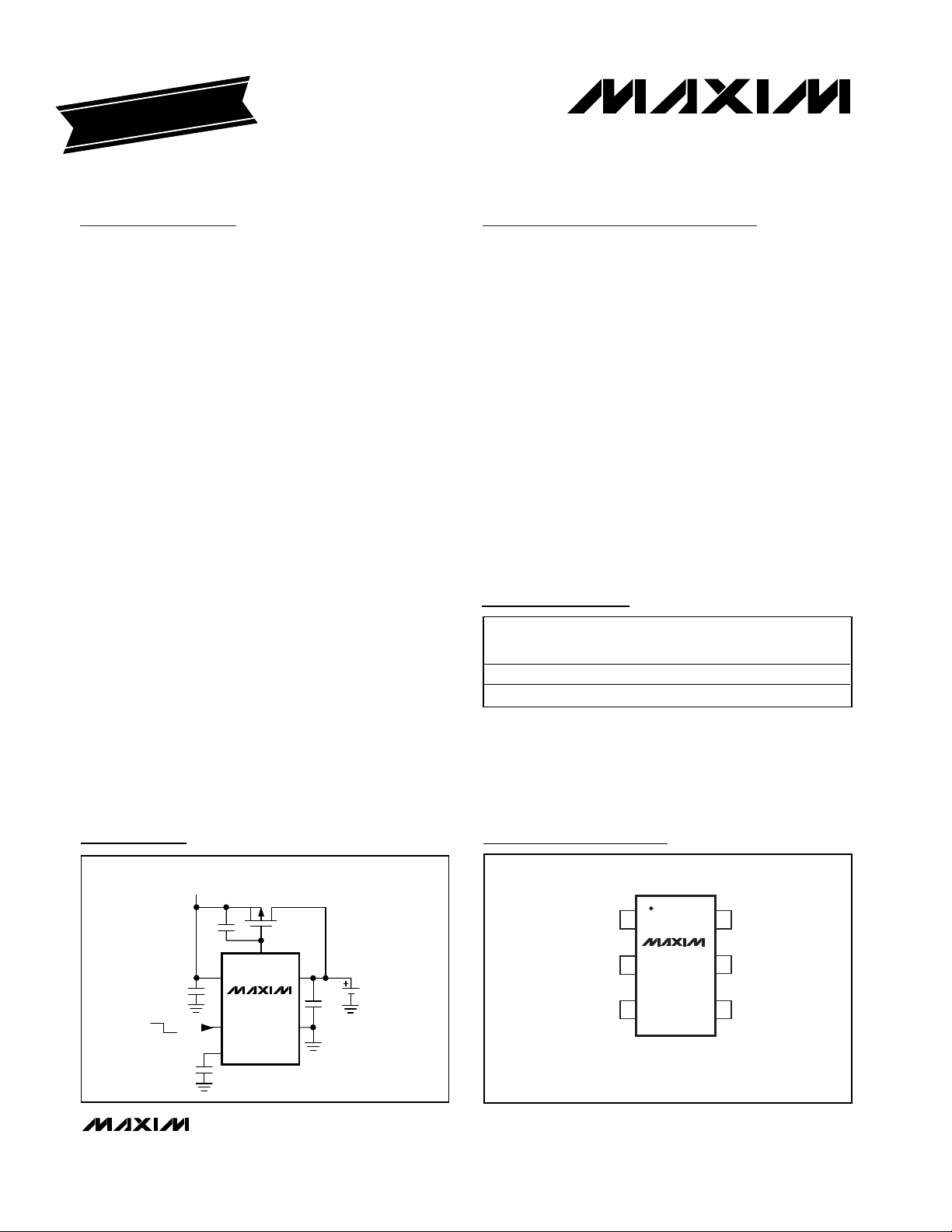
CURRENT-LIMITED
VOLTAGE SOURCE
GATE
BATT
BATTERY
GND
IN
EN
CT
ON
OFF
MAX1736
PFET
Typical Operating Circuit
19-1662; Rev 1; 10/00
EVALUATION KIT
AVAILABLE
Ordering Information
For price, delivery, and to place orders, please contact Maxim Distribution at 1-888-629-4642,
or visit Maxim’s website at www.maxim-ic.com.
PART
MAX1736EUT42-T -40°C to +85°C 6 SOT23-6 AAHO
MAX1736EUT41-T -40°C to +85°C 6 SOT23-6 AANC
TEMP.
RANGE
PINPACKAGE
SOT
MARK
TOP VIEW
IN
GATE
16BATT
MAX1736
2
34
SOT23
5 CT
ENGND
MAX1736
SOT23, Single-Cell Li+ Battery Charger
for Current-Limited Supply
2 _______________________________________________________________________________________
ABSOLUTE MAXIMUM RATINGS
Stresses beyond those listed under “Absolute Maximum Ratings” may cause permanent damage to the device. These are stress ratings only, and functional
operation of the device at these or any other conditions beyond those indicated in the operational sections of the specifications is not implied. Exposure to
absolute maximum rating conditions for extended periods may affect device reliability.
IN, GATE to GND....................................................-0.3V to +26V
BATT, EN, CT to GND ..............................................-0.3V to +6V
GATE to IN................................................................-6V to +0.3V
GATE Continuous Current.................................-10mA to +10mA
Continuous Power Dissipation (T
A
= +70°C) (Note 1)
6-Pin SOT23 (derate 8.1mW/°C above +70°C).............0.65W
Operating Temperature Range ...........................-40°C to +85°C
Storage Temperature Range ..............................-65°C to +150°C
Maximum Junction Temperature ......................................+150°C
Lead Temperature (soldering, 10s) (Note 2) ...................+300°C
ELECTRICAL CHARACTERISTICS
(VIN= 10V, V
BATT
= 4.2V for MAX1736EUT42 or 4.1V for MAX1736EUT41, TA= 0°C to +85°C. Typical values are at TA= +25°C,
unless otherwise noted.) (Note 3)
Note 1: Thermal properties are specified with product mounted on PC board with one square-inch of copper area and still air.
Note 2: This device is constructed using a unique set of packaging techniques that impose a limit on the termal profile the device can be
exposed to during solder attach and rework. This limit permits only the use of the solder profiles recommended in the industry standard specification, IPC/JEDEC J-STD-020A, paragraph 7.6, Table 3 for the IR/VPR and Convention reflow. Pre-heating is required.
Hand or wave soldering is not allowed.
Input Voltage (Note 4) External P-MOSFET off 4.7 22 V
Fast-Charge BATT Qualification
Threshold
Fast-Charge BATT Qualification
Threshold Hysteresis
BATT Regulation Voltage
BATT Removal Detection
Threshold
BATT Removal Detection
Threshold Hysteresis
BATT Input Current, Input Power
Removed
BATT Input Current, Charger
Disabled
BATT Input Current, When
Charging
Precharge Source Current V
IN Input Current 0.25 1 mA
IN Detection Interval (Note 5) C
GATE Source/Sink Current 75 100 125 µA
GATE Drive Source Current at
Battery Removal
Minimum BATT Bypass
Capacitance (Note 6)
EN Logic High Threshold 2V
EN Logic Low Threshold 0.7 V
CT Pulldown Current 1.6 2 2.4 µA
PARAMETER CONDITIONS MIN TYP MAX UNITS
BATT rising, transition from precharge to fast charge 2.4 2.5 2.65 V
MAX1736EUT42 4.179 4.20 4.221
MAX1736EUT41 4.079 4.10 4.121
BATT rising 4.875 5.0 5.1 V
V
≤ V
IN
EN = GND, V
BATT
CT
V
BATT
- 0.3V 0.1 1 µA
BATT
= 0 to 5V 2 6 µA
BATT
= 2V 3.5 6 8 mA
= 0.33µF 20 s
= 5.1V 15 30 60 mA
70 mV
V
125 mV
0.4 0.75 mA
1.5 µF/A
MAX1736
SOT23, Single-Cell Li+ Battery Charger
for Current-Limited Supply
_______________________________________________________________________________________ 3
ELECTRICAL CHARACTERISTICS (continued)
(VIN= 10V, V
BATT
= 4.2V for MAX1736EUT42 or 4.1V for MAX1736EUT41, TA= 0°C to +85°C. Typical values are at TA= +25°C,
unless otherwise noted.)
ELECTRICAL CHARACTERISTICS
(VIN= 10V, V
BATT
= 4.2V for MAX1736EUT42 or 4.1V for MAX1736EUT41, TA= -40°C to +85°C, unless otherwise noted.) (Note 3)
Note 3: All devices are 100% production tested at TA= +25°C. Limits over the operating temperature range are guaranteed by
design.
Note 4: The input voltage range is specified with the external PFET off. When charging, the PFET turns on and the input voltage (the
output voltage of the constant-current power source) drops to very near the battery voltage. When the PFET is on, IN may be
as low as 2.5V.
Note 5: Every 20s (for CT = 0.33µF) the MAX1736 turns off the external P-channel MOSFET and samples IN to determine if input
power is present. If input power is removed, the charger shuts down.
Note 6: For design guidance, not tested.
CT Pullup Current -12 -10 -8
Minimum On-Time C
Minimum Off-Time C
EN Pullup Resistance 175 350 725 kΩ
PARAMETER CONDITIONS MIN TYP MAX UNITS
= 0.33µF 165 ms
CT
= 0.33µF 33 ms
CT
µA
Input Voltage (Note 4) External P-MOSFET off 4.7 22 V
Fast-Charge BATT Qualification
Threshold
BATT Regulation Voltage
BATT Removal Detection
Threshold
BATT Input Current, Input Power
Removed
BATT Input Current, Charger
Disabled
BATT Input Current, When
Charging
Precharge Source Current V
IN Input Current 1mA
GATE Source/Sink Current 60 140 µA
GATE Drive Source Current at
Battery Removal
EN Logic High Threshold 2 V
EN Logic Low Threshold 0.7 V
CT Pulldown Current 1.5 2.5 µA
CT Pullup Current -12 -8 µA
EN Pullup Resistance 170 725 kΩ
PARAMETER CONDITIONS MIN MAX UNITS
BATT rising, transition from precharge to fast charge 2.4 2.65 V
MAX1736EUT42 4.158 4.242 V
MAX1736EUT41 4.058 4.142
BATT rising 4.85 5.125 V
VIN ≤ V
EN = GND, V
BATT
V
BATT
- 0.3V 1 µA
BATT
= 0 to 5V 6 µA
BATT
0.75 mA
= 2V 3 8 mA
= 5.1V 10 90 mA

MAX1736
SOT23, Single-Cell Li+ Battery Charger
for Current-Limited Supply
4 _______________________________________________________________________________________
Typical Operating Characteristics
(TA = +25°C, unless otherwise noted.)
MINIMUM ON/OFF-TIMES vs. C
10,000
1000
100
MINIMUM ON/OFF-TIME (ms)
10
0.1 1 10
MINIMUM
ON-TIME
INPUT DETECTION INTERVAL (s)
CT
MAX1736 toc01
MINIMUM
OFF-TIME
CCT (µF)
BATT VOLTAGE DEVIATION (%)
INPUT DETECTION INTERVAL vs. C
1000
100
10
1
0.1 1 10
CCT (µF)
BATT REGULATION VOLTAGE
DEVIATION vs. TEMPERATURE
0.20
0.15
0.10
0.05
0.00
-0.05
-0.10
-0.15
-0.20
-40 -15 10 35 60 85
TEMPERATURE (°C)
CT
MAX1736 toc04
5V/div
V
BATT
200mV/div
AC-COUPLED
1A/div
V
GATE
10V/div
5.8
5.7
MAX1736-02
5.6
5.5
5.4
5.3
PRECHARGE CURRENT (mA)
PRECHARGE CURRENT (mA)
5.2
5.1
4 9 14 19 24
TYPICAL OPERATING WAVEFORMS
I
IN
OV
I
IN
OA
PFET OFF
10ms/div
PRECHARGE CURRENT vs.
INPUT VOLTAGE
V
= 0
BATT
V
= 1V
BATT
V
= 2V
BATT
VIN (V)
PFET ON
MAX1736 toc05
MAX1736-03

MAX1736
SOT23, Single-Cell Li+ Battery Charger
for Current-Limited Supply
_______________________________________________________________________________________ 5
Pin Description
Detailed Description
The MAX1736 provides a simple, safe, low-cost method
of charging a single-cell Li+ battery with nearly no heat
generation. Combined with a current-limited voltage
source, the MAX1736 provides precharge, fast-charge,
and top-off-charge capabilities. After constant-current
fast charge, top-off safely finishes charging the battery
by pulse-width modulating charge current. The top-off
on-time is kept below the electrochemical time constant
of the cell. The key advantage of this method is that the
charge circuit is small and generates minimal heat
while providing a safe method of charging to ensure
maximum cell life. Figure 1 shows the MAX1736 functional diagram.
Precharge
To protect Li+ cells from damage that may occur if fast
charged from a dead state, the MAX1736 precharges the
Li+ cell with 6mA at the start of a charging cycle when the
cell voltage is below 2.5V. As soon as the cell voltage
reaches 2.5V, the MAX1736 begins fast charging.
Fast Charge
In fast-charge mode, the MAX1736 turns on the external P-channel MOSFET. Charging current is set by the
current limit of the external supply; current is not regu-
lated by the MAX1736. The P-channel MOSFET is
used only as a switch, not as a linear regulator.
Therefore, the circuit’s power dissipation is minimized,
permitting rapid charge cycles with almost no heat
generation. The external power supply should have a
specified current limit that matches the desired fastcharge current for the Li+ cell.
With the P-channel MOSFET on, VINwill be nearly
equal to V
BATT
. To detect that an input supply is connected, the MAX1736 periodically turns the P-channel
MOSFET off and checks the voltage at IN. During fast
charge, this occurs once every input detection interval
(20s with CCT= 0.33µF). During pulsed top-off, input
detection occurs more frequently and is continuous
when the MOSFET is off (see Selecting External
Components).
Pulsed Top-Off
When the battery approaches full charge, its instantaneous voltage reaches the BATT regulation voltage and
pulsed top-off begins. The MAX1736 uses a hysteretic
algorithm with a minimum on- and off-time. Cell voltage
is sampled with no charging current to minimize errors
due to battery and cell protection resistance.
If the voltage is below the BATT regulation voltage, the
P-channel MOSFET switches on for a minimum on-time.
If, at the end of the minimum on-time, the cell voltage is
still below the BATT regulation voltage, the switch
remains on until the cell voltage reaches the BATT regulation voltage. At that point, the P-channel MOSFET
then switches off for at least the minimum off-time. The
minimum on-time is set by CT and should be set below
the electrochemical time constant of the cell. A C
CT
value of 0.33µF sets a minimum on-time of 165ms,
which is adequate for most Li+ batteries.
PIN NAME DESCRIPTION
1IN
2 GATE
3 GND Ground. Connect the battery’s negative terminal to GND.
4EN
5CT
6 BATT
Input Voltage from Current-Limited Voltage Source (22V max). Bypass to GND with a 0.1µF
capacitor. The charging current is set by the current limit of the external power supply.
Gate Drive for External PMOS Pass Element. The PMOS device should have a V
of 2.5V or less (see Selecting External Components).
Logic-Level Enable Input. Pull low to disable the MAX1736. EN is internally pulled up to V
100mV through 350kΩ, but draws no current from BATT.
Charge Time Control. Sets the minimum on-time, minimum off-time, and the IN detection interval.
Place a 0.33µF capacitor between CT and GND for most applications (see Selecting External
Components).
Cell Voltage Monitor Input, Precharge Current Output, and MAX1736 Power Source. Connect BATT
to the positive terminal of a single Li+ cell. Bypass BATT with a capacitor to GND (1.5µF per amp of
charge current).
threshold
GS
BATT
+

6 ____________________________________________________________________________________________________
Once the switch turns off, it remains off for at least the
minimum off-time. After the minimum off-time, the Pchannel MOSFET turns on if the cell voltage is lower
than the BATT regulation voltage. A CCTvalue of
0.33µF sets a minimum off-time of 33ms.
At the beginning of the pulsed top-off state, charge current is modulated at approximately an 83% duty cycle.
Toward the end of top-off, charge current stays off for
long periods of time between single “on” pulses. During
these final pulses, the instantaneous cell voltage may
exceed the BATT regulation voltage by several hundred millivolts, but these pulses are orders of magnitude shorter than the electrochemical time constant of
the Li+ cell and do no harm. Pulsed top-off charge
ends when the cell voltage no longer falls below the
BATT regulation voltage. Figure 2 shows the state
machine.
Selecting External Components
Input Power Supply
One reason the MAX1736 Li+ charger is so compact
and simple is that the charging current is set by the
external power source, not by the MAX1736. The Pchannel MOSFET in Figure 3’s application circuit is
either on or off, allowing the source to be directly connected to the cell or disconnected. Therefore, it is
important to choose a power supply with the correct
current limit for the cell to be charged. In most applications, this will be a small wall cube with an open-circuit
output voltage of 5V to 12V, which is specified as “current limited” or “constant current.”
Some low-cost wall cubes may have poor transient
characteristics. For these wall cubes, output current
may exceed the specified current limit by several times
when the load is quickly connected. The MAX1736 limits this current peak by controlling the slew rate of the
P-channel MOSFET. See C
CT
and C
GATE
for more
information.
PMOS Switch
The P-channel MOSFET switches the current-limited
source on and off. Because of the intentionally slow
switching times and limited slew rate, the MAX1736 is
not particular about the power FET it drives. Specifications to consider when choosing an appropriate
MAX1736
SOT23, Single-Cell Li+ Battery Charger
for Current-Limited Supply
Figure 1. Functional Diagram
IN
V
BATT
10µA
CT
2µA
+ 100mV
350k
EN IN
1.4V
0.4V
STAT E
MACHINE
GND
GATE
REF
IN
6mA
4.2V (4.1V)
5V
MAX1736EUT42
(MAX1736EUT41)
BATT

FET are the minimum drain-source breakdown voltage
and the minimum turn-on threshold voltage (VGS).
Power dissipation during fast charge is approximately
R
DSON
✕
I
CHG
2
, where I
CHG
is the current limit set by
the input power source. The minimum breakdown voltage (BVDS) must typically be two times the wall cube’s
open-circuit voltage. An even larger margin may be
necessary if the wall adapter has especially poor transient response. The MAX1736 can operate with input
voltages up to 22V.
BATT Capacitor
Bypass BATT with at least 1.5µF per amp of charge
current. If the battery is removed while the P-channel
MOSFET is on, a BATT voltage over 5V is quickly
sensed, and the FET is immediately turned off. In applications where the cell is removable, very large capacitance values may increase transient currents when the
cell is replaced. Therefore, BATT capacitance in
excess of 100µF should be avoided. For best system
performance with large output capacitance, at least
0.47µF of the total capacitance should be low-ESR
ceramic.
CCTand C
GATE
Most applications will use the circuit of Figure 3 with
C
GATE
= 0.22µF, R
GATE
= 100kΩ, and CCT= 0.33µF.
C
GATE
, R
GATE
, and the internal 100µA pull-up and pulldown current sources act to slow the switching of the Pchannel MOSFET. This prevents a wall cube with poor
transient response from subjecting VINto excessive
voltage when the P-channel MOSFET turns off, and prevents excessive current into the battery when the Pchannel MOSFET turns on. Excessive voltage at V
IN
can potentially damage the IC, input capacitor, and the
PMOS switch. Excessive current into the battery can
cause errors in the termination process of the MAX1736
(by raising the instantaneous battery voltage) and may
trip the battery’s protection circuitry.
In applications utilizing a wall cube with poor transient
response, increase the value of C
GATE
as needed to
MAX1736
SOT23, Single-Cell Li+ Battery Charger
for Current-Limited Supply
_______________________________________________________________________________________ 7
Figure 2. State Machine
CHARGER
POWER REMOVED
(FROM ANY STATE)
SHUTDOWN
FET: OFF
TOP-OFF QUAL
FET: OFF
EVERY
CYCLE
TOP-OFF
FET: PULSED
CHARGER
POWER
PRESENT
CHARGER
POWER
PRESENT
> 4.2V
V
BATT
DETECTION
INTERVAL
(FROM ANY STATE)
EN
DISABLED
FET: OFF
FAST-CHARGE QUAL
FET: OFF
IN
FAST-CHARGE
FET: ON
CHARGER
POWER
PRESENT
PRECHARGE
FET: OFF
= -6mA
I
≥ 2.5V
BATT
V
OUT
< 2.5V
BATT
V
< 2.5V
BATT
V
EN

MAX1736
Maxim cannot assume responsibility for use of any circuitry other than circuitry entirely embodied in a Maxim product. No circuit patent licenses are
implied. Maxim reserves the right to change the circuitry and specifications without notice at any time.
8 _____________________Maxim Integrated Products, 120 San Gabriel Drive, Sunnyvale, CA 94086 408-737-7600
© 2000 Maxim Integrated Products Printed USA is a registered trademark of Maxim Integrated Products.
further slow switching edges and prevent transient
spikes.
CCTsets the minimum on-time and off-time according
to the following equations:
t
ON(MIN)
= 5 ✕105x C
CT
t
OFF(MIN)
= 1 ✕105x C
CT
Layout Guidelines
The MAX1736 controls the GATE slew rate; consequently, PC board layout is not as sensitive to noise as
a high-frequency switching regulator. In addition, since
cell voltage is sensed both during and between highcurrent pulses, the system is insensitive to ground
errors. However, Maxim recommends maintaining large
ground area and large traces for high-current paths.
Refer to the MAX1736EVKIT for a recommended layout
example.
Chip Information
TRANSISTOR COUNT: 1622
Figure 3. Simple Application Circuit
Package Information
SOT23, Single-Cell Li+ Battery Charger
for Current-Limited Supply
CURRENT-LIMITED
WALL CUBE
(800mA)
100k
0.22µF
0.1µF
0.33µF
IN
CT
FDC638P
PFET
GATE
MAX1736
BATT
GND
2.2µF
6LSOT.EPS
SINGLE
Li+ CELL

 Loading...