

Page 1
General Description
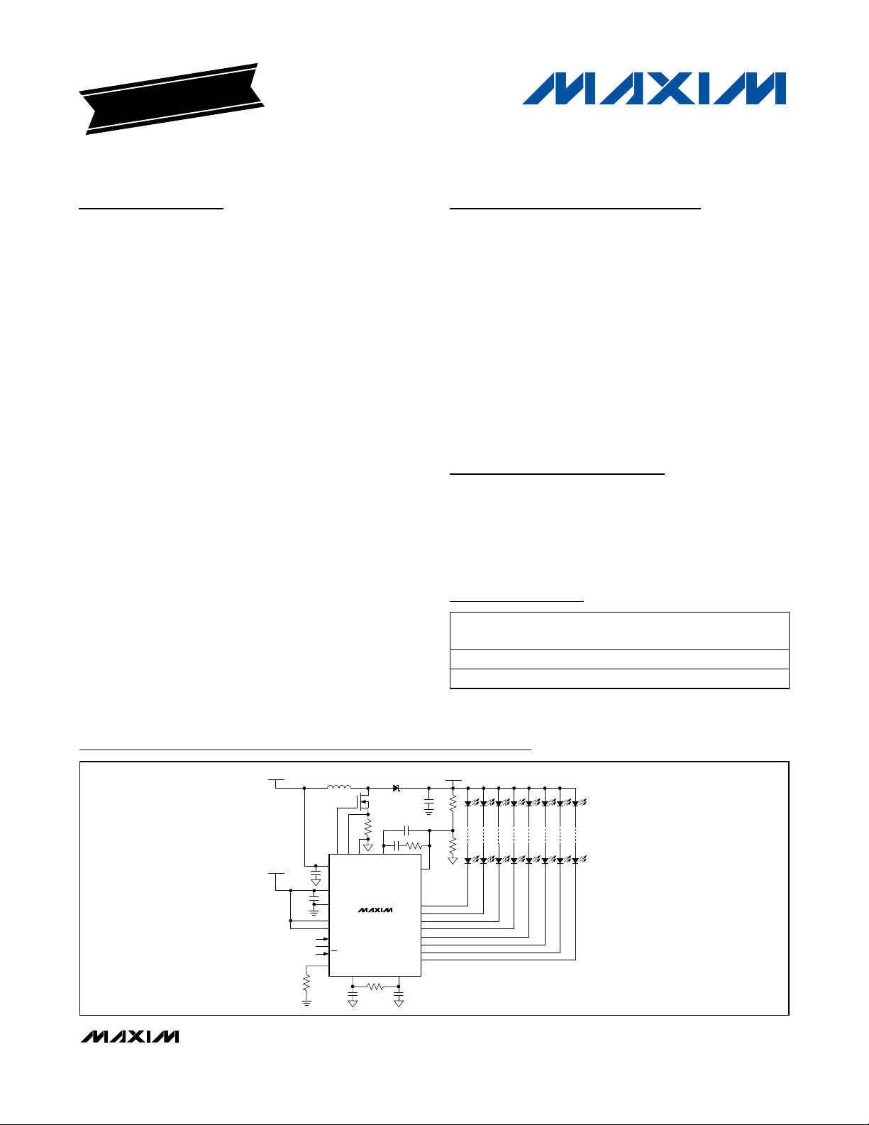
The MAX16807/MAX16808 are integrated, high-efficiency white or RGB LED drivers. They are designed for
LCD backlighting and other LED lighting applications
with multiple strings of LEDs. The MAX16807/
MAX16808’s current-mode PWM controller regulates
the necessary voltage to the LED array. Depending on
the input voltage and LED voltage range, it can be
used with boost or buck-boost (SEPIC) topologies. The
MAX16807/MAX16808 feature an 8V to 26.5V input voltage range. A wide range of adjustable frequency
(20kHz to 1MHz) allows design optimization for efficiency and minimum board space.
The MAX16807/MAX16808 LED drivers include eight
open-drain, constant-current-sinking LED driver outputs
rated for 36V continuous operation. The LED currentcontrol circuitry achieves ±3% current matching among
strings and enables paralleling of outputs for LED string
currents higher than 55mA. The output-enable pin is
used for simultaneous PWM dimming of all output channels. Dimming frequency range is 50Hz to 30kHz and
dimming ratio is up to 5000:1. The constant-current outputs are single resistor programmable and the LED current can be adjusted up to 55mA per output channel.
The MAX16807/MAX16808 operate either in stand-alone
mode or with a microcontroller (µC) using an industrystandard, 4-wire serial interface. The MAX16808 includes
circuitry that automatically detects open-circuit LEDs.
The MAX16807/MAX16808 include overtemperature
protection, operate over the full -40°C to +125°C temperature range, and are available in a thermally
enhanced, 28-pin TSSOP exposed paddle package.
Features
o Eight Constant-Current Output Channels (Up to
55mA Each)
o ±3% Current Matching Among Outputs
o Paralleling Channels Allows Higher Current per
LED String
o Outputs Rated for 36V Continuous Voltage
o Output-Enable Pin for PWM Dimming (Up to 30kHz)
o One Resistor Sets LED Current for All Channels
o Wide Dimming Ratio Up to 5000:1
o Low Current-Sense Reference (300mV) for High
Efficiency
o 8V to 26.5V Input Voltage or Higher with External
Biasing Devices
o Open LED Detection (MAX16808)
o 4-Wire Serial Interface to Control Individual
Output Channels
Applications
LCD White or RGB LED Backlighting:
LCD TVs, Desktop, and Notebook Panels
Automotive Navigation, Heads-Up,
and Infotainment Displays
Industrial and Medical Displays
Ambient, Mood, and Accent Lighting
MAX16807/MAX16808
Integrated 8-Channel LED Drivers with
Switch-Mode Boost and SEPIC Controller
________________________________________________________________
Maxim Integrated Products
1
19-0655; Rev 1; 4/07
For pricing, delivery, and ordering information, please contact Maxim Direct at 1-888-629-4642,
or visit Maxim’s website at www.maxim-ic.com.
EVALUATION KIT
AVAILABLE
Pin Configurations appear at end of data sheet.
Ordering Information
Typical Operating Circuits
+
Denotes a lead-free package.
*
EP = Exposed paddle.
Typical Operating Circuits continued at end of data sheet.
V
3V TO 5.5V
IN
R
SET
C
IN
C
BYP
L
Q
R
OUT CS AGND COMP
V
CC
V+
PGND
MAX16807
LE
MAX16808
DIN
CLK
DOUT
OE
SET
REF
R
C
REF
D
C
CS
C
C1
RTCT
T
C
T
PA R T
M A X1 6 8 0 7 AU I+ - 40°C to + 125°C 28 TS S O P - E P *U 28M E - 1
M A X1 6 8 0 8 AU I+ - 40°C to + 125°C 28 TS S O P - E P *U 28M E - 1
T EM P
R A N G E
PIN - PA C K A G E
V
OUT
C
OUT
R1
C2
R
C1
R2
FB
OUT0
OUT1
OUT2
OUT3
OUT4
OUT5
OUT6
OUT7
STAND-ALONE OPERATION
LEDs
PK G
C O D E
Page 2
MAX16807/MAX16808
Integrated 8-Channel LED Drivers with
Switch-Mode Boost and SEPIC Controller
2 _______________________________________________________________________________________
ABSOLUTE MAXIMUM RATINGS
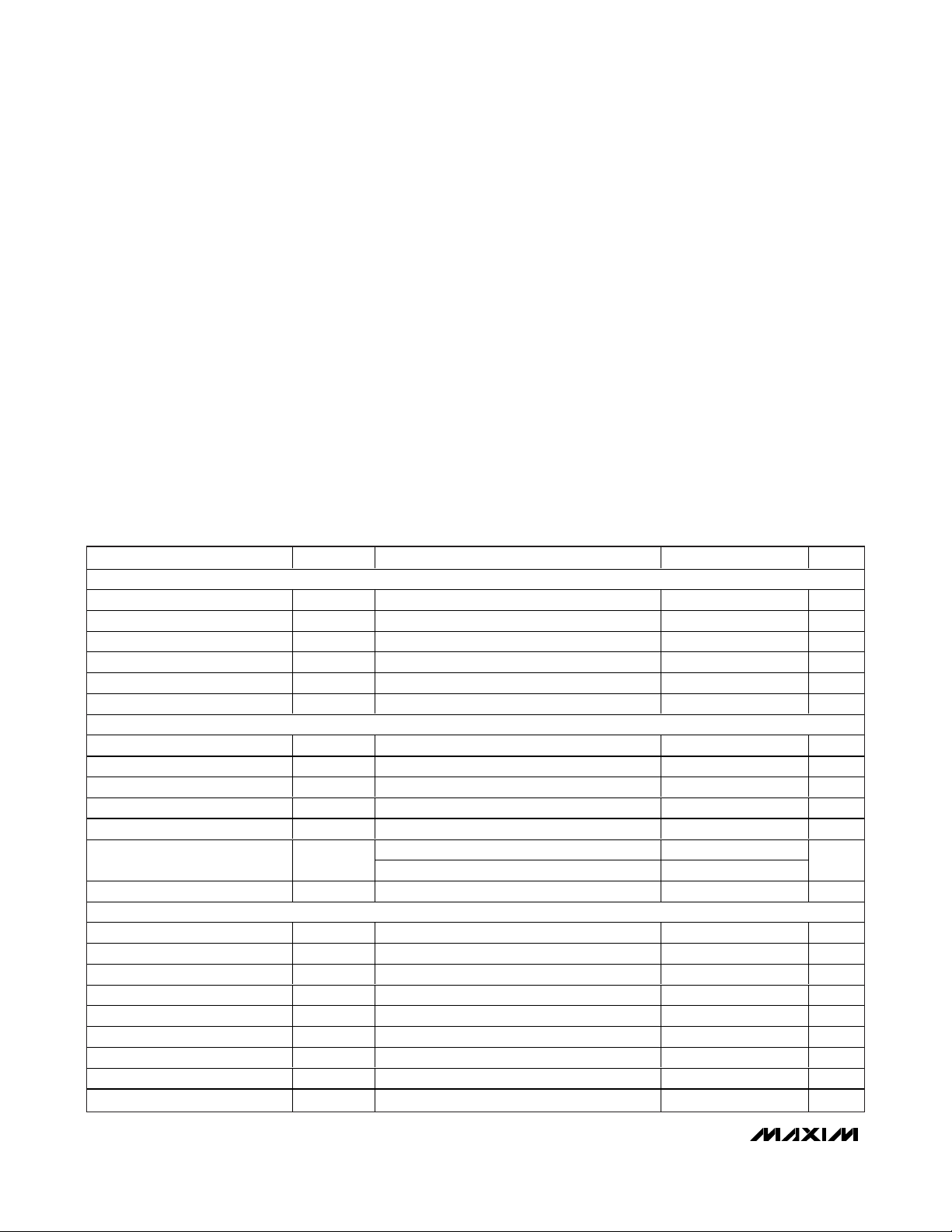
ELECTRICAL CHARACTERISTICS (PWM CONTROLLER)
(VCC= +15V, V+ = +3V to +5.5V referenced to PGND, RT= 10kΩ, CT= 3.3nF, REF = open, COMP = open, C
REF
= 0.1µF, VFB= 2V,
CS = AGND, AGND = PGND = 0V; all voltages are measured with respect to AGND, unless otherwise noted. T
J
= TA = -40°C to
+125°C, unless otherwise noted. Typical values are at T
A
= +25°C.) (Note 1)
Stresses beyond those listed under “Absolute Maximum Ratings” may cause permanent damage to the device. These are stress ratings only, and functional
operation of the device at these or any other conditions beyond those indicated in the operational sections of the specifications is not implied. Exposure to
absolute maximum rating conditions for extended periods may affect device reliability.
VCCto AGND..........................................................-0.3V to +30V
Current into V
CC (VCC
> 24V)...........................................±30mA
V+ to PGND..............................................................-0.3V to +6V
OUT to AGND.............................................-0.3V to (V
CC
+ 0.3V)
OUT Current (10µs duration) .................................................±1A
FB, COMP, CS, RTCT, REF to AGND.......................-0.3V to +6V
COMP Sink Current.............................................................10mA
OUT0–OUT7 to PGND............................................-0.3V to +40V
DIN, CLK, LE, OE, SET to PGND..................-0.3V to (V+ + 0.3V)
DOUT Current...................................................................±10mA
OUT0–OUT7 Sink Current...................................................60mA
Total PGND Current ..........................................................480mA
Continuous Power Dissipation (T
A
= +70°C)
28-Pin TSSOP (derate 27mW/°C* above +70°C).......2162mW
Operating Temperature Range .........................-40°C to +125°C
Junction Temperature......................................................+150°C
Storage Temperature Range .............................-65°C to +150°C
Lead Temperature (soldering, 10s) .................................+300°C
*
Per JEDEC51 Standard (Multilayer Board).
PARAMETER SYMBOL CONDITIONS MIN TYP MAX UNITS
REFERENCE
Output Voltage V
Line Regulation ΔV
Load Regulation ΔV
Total Output-Voltage Variation V
Output Noise Voltage V
Output Short-Circuit Current I
REF
LINE
LOAD
REFT
NOISE
SHORT
OSCILLATOR
Initial Accuracy TJ = +25°C 51 54 57 kHz
Voltage Stability 12V < VCC < 25V 0.2 0.5 %
Temperature Stability 1%
RTCT Ramp Peak-to-Peak 1.7 V
RTCT Ramp Valley 1.1 V
Discharge Current I
Frequency Range f
DIS
OSC
ERROR AMPLIFIER
FB Input Voltage V
Input Bias Current I
Open-Loop Gain A
Unity-Gain Bandwidth f
FB
B(FB)
VOL
GBW
Power-Supply Rejection Ratio PSRR 12V ≤ VCC ≤ 25V 60 80 dB
COMP Sink Current I
COMP Source Current I
COMP Output-Voltage High V
COMP Output-Voltage Low V
SINK
SOURCE
OH
OL
I
= 1mA, T
REF
12V< V
CC
1mA < I
REF
(Note 2) 4.875 5.125 V
10Hz < f < 10kHz 50 µV
V
= 0V 30 180 mA
REF
V
= 2V, TJ = +25°C 7.9 8.3 8.7
RTCT
V
= 2V, -40oC ≤ TJ ≤ +125°C 7.5 8.3 9.0
RTCT
FB shorted to COMP 2.45 2.50 2.55 V
2V ≤ V
COMP
VFB = 2.7V, V
VFB = 2.3V, V
VFB = 2.3V, R
VFB = 2.7V, R
= +25°C 4.95 5 5.05 V
J
< 25V, I
= 1mA 0.4 4 mV
REF
< 20mA 6 50 mV
20 1000 kHz
-0.01 -0.1 µA
≤ 4V 100 dB
1 MHz
= 1.1V 2 6 mA
COMP
= 5V 0.5 1.2 1.8 mA
COMP
= 15kΩ to AGND 5 5.8 V
COMP
COMP
= 15kΩ to V
REF
0.1 1.1 V
mA
Page 3
MAX16807/MAX16808
Integrated 8-Channel LED Drivers with
Switch-Mode Boost and SEPIC Controller
_______________________________________________________________________________________ 3
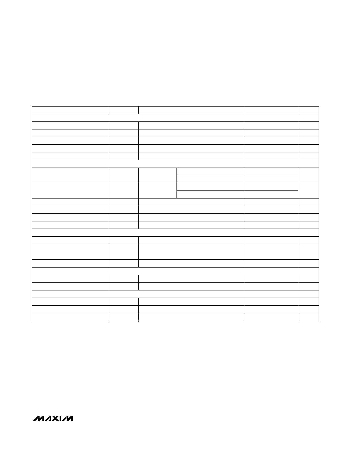
ELECTRICAL CHARACTERISTICS (PWM CONTROLLER) (continued)
(VCC= +15V, V+ = +3V to +5.5V referenced to PGND, RT= 10kΩ, CT= 3.3nF, REF = open, COMP = open, C
REF
= 0.1µF, VFB= 2V,
CS = AGND, AGND = PGND = 0V; all voltages are measured with respect to AGND, unless otherwise noted. T
J
= TA = -40°C to
+125°C, unless otherwise noted. Typical values are at T
A
= +25°C.) (Note 1)
PARAMETER SYMBOL CONDITIONS MIN TYP MAX UNITS
CURRENT-SENSE AMPLIFIER
Current-Sense Gain A
Maximum Current-Sense Signal V
Power-Supply Rejection Ratio PSRR 12V ≤ VCC ≤ 25V 70 dB
Current-Sense Input Bias Current I
Current Sense to OUT Delay t
MOSFET DRIVER
OUT Low-Side On-Resistance V
OUT High-Side On-Resistance V
Source Current (Peak) I
Sink Current (Peak) I
Rise Time t
Fall Time t
UNDERVOLTAGE LOCKOUT/STARTUP
Startup Voltage Threshold V
Minimum Operating Voltage After
Turn-On
Undervoltage-Lockout Hysteresis UVLO
PULSE-WIDTH MODULATION (PWM)
Maximum Duty Cycle D
Minimum Duty Cycle D
SUPPLY CURRENT
Startup Supply Current I
Operating Supply Current I
VCC Zener Voltage V
CS
CS_MAX
CS
PWM
RDS_ONL
RDS_ONH
SOURCE
SINK
R
F
CC_START
V
CC_MIN
HYST
MAX
MIN
START
CC
Z
(Notes 3, 4) 2.85 3.00 3.40 V/V
(Note 3) 0.275 0.300 0.325 V
V
= 0V -1 -2.5 µA
COMP
50mV overdrive 60 ns
I
= 200mA
SINK
I
100mA
C
C
C
C
VCC = 7.5V 32 65 µA
VFB = VCS = 0V 3 5 mA
ICC = 25mA 24 26.5 V
=
SOURCE
= 10nF 2 A
LOAD
= 10nF 1 A
LOAD
= 1nF 15 ns
LOAD
= 1nF 22 ns
LOAD
TJ = -40°C to +85°C (Note 2) 4.5 10
= -40°C to +125°C 4.5 12
T
J
TJ = -40°C to +85°C (Note 2) 3.5 7.5
T
= -40°C to +125°C 3.5 10
J
7.98 8.4 8.82 V
7.1 7.6 8.0 V
94.5 96 97.5 %
0.8 V
0%
Ω
Ω
Page 4

MAX16807/MAX16808
Integrated 8-Channel LED Drivers with
Switch-Mode Boost and SEPIC Controller
4 _______________________________________________________________________________________
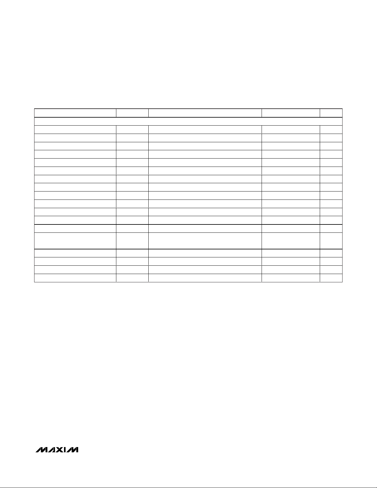
ELECTRICAL CHARACTERISTICS (LED DRIVER)
(V+ = +3V to +5.5V, AGND = PGND = 0V; all voltages are measured with respect to PGND, unless otherwise noted. TA= TJ= -40°C
to +125°C, unless otherwise noted. Typical values are at T
A
= +25°C.) (Note 1)
PARAMETER SYMBOL CONDITIONS MIN TYP MAX UNITS
Operating Supply Voltage V+ 3.0 5.5 V
Output Voltage V
Standby Current (Interface Idle, All
Output Ports High Impedance)
Standby Current
(Interface Active, All Output Ports
High Impedance)
OUT_
R
OE = V+, DOUT unconnected
R
DIN, LE = PGND or V+, DOUT unconnected
= 360Ω, DIN, LE, CLK = PGND or V+,
SET
= 360Ω, f
SET
= 5MHz, OE = V+,
CLK
36 V
3.6 4.5 mA
3.8 4.8 mA
Supply Current
(Interface Idle, All Output Ports
Active Low)
INTERFACE (DIN, CLK, DOUT, LE, OE)
Input-Voltage High
(DIN, CLK, LE, OE)
Input-Voltage Low
(DIN, CLK, LE, OE)
Hysteresis Voltage
(DIN, CLK, LE, OE)
Input Leakage Current
(DIN, CLK)
OE Pullup Current to V+ I
LE Pulldown Current to PGND I
Output-Voltage High (DOUT) V
Output-Voltage Low (DOUT) V
OUT_ Output Current I
OUT_ Leakage Current OE = V+ 1 µA
OUT_ Fault Detection Threshold
(MAX16808)
I+
V
V
V
HYST
I
LEAK
OE
OUT_
V
OUTTH
R
= 360Ω, OE = PGND, DIN,
SET
LE = V+, DOUT unconnected
IH
IL
V+ = 5.5V, OE = PGND 0.25 1.5 25.0 µA
V+ = 5.5V, LE = V+ 0.25 1.5 25.0 µA
LE
I
OH
I
OL
0oC ≤ TA ≤ +125°C, V
360Ω
TA = -40°C, V
R
V+ = 5.5V, OE = V+ 0.8 V
= 4mA
SOURCE
= 4mA 0.5 V
SINK
= 1V to 2.5V, R
SET
= 360Ω
= 1V to 2.5V,
OUT
OUT
SET
0.7
x V+
-1 +1 µA
V+
- 0.5V
=
46.5 50 53.5
43 57
17 30 mA
0.8 V
0.3
x V+
V
V
V
mA
Page 5
MAX16807/MAX16808
Integrated 8-Channel LED Drivers with
Switch-Mode Boost and SEPIC Controller
_______________________________________________________________________________________ 5
5V TIMING CHARACTERISTICS
(V+ = +4.5V to +5.5V, AGND = PGND = 0V; all voltages are measured with respect to PGND, unless otherwise noted. TA= TJ= -40°C
to +125°C, unless otherwise noted. Typical values are at TA = +25°C.) (Notes 1, 5)
PARAMETER SYMBOL CONDITION MIN TYP MAX UNITS
INTERFACE TIMING CHARACTERISTICS
CLK Clock Period t
CLK Pulse-Width High t
CLK Pulse-Width Low t
DIN Setup Time t
DIN Hold Time t
DOUT Propagation Delay t
DOUT Rise Time t
DOUT Fall Time t
LE Pulse-Width High t
LE Setup Time t
LE Rising to OUT_ Rising Delay t
LE Rising to OUT_ Falling Delay t
CLK Rising to OUT_ Rising Delay t
CLK Rising to OUT_ Falling
Delay
OE Rising to OUT_ Rising Delay t
OE Falling to OUT_ Falling Delay t
OUT_ Turn-On Fall Time t
OUT_ Turn-Off Rise Time t
CH
DH
DO
DR
LW
LRR
LRF
CRR
t
CRF
OER
OEF
CP
CL
DS
DF
LS
C
= 10pF, 20% to 80% 10 ns
DOUT
C
= 10pF, 80% to 20% 10 ns
DOUT
(Note 6) 110 ns
(Note 6) 325 ns
(Note 6) 110 ns
(Note 6) 325 ns
(Note 6) 110 ns
(Note 6) 325 ns
F
R
80% to 20% (Note 6) 210 ns
20% to 80% (Note 6) 130 ns
40 ns
19 ns
19 ns
4ns
8ns
12 50 ns
20 ns
15 ns
Page 6
MAX16807/MAX16808
Integrated 8-Channel LED Drivers with
Switch-Mode Boost and SEPIC Controller
6 _______________________________________________________________________________________
3.3V TIMING CHARACTERISTICS
(V+ = +3V to < +4.5V, AGND = PGND = 0V; all voltages are measured with respect to PGND, unless otherwise noted. TA= TJ= -40°C
to +125°C, unless otherwise noted. Typical values are at TA = +25°C.) (Notes 1, 5)
Note 1: All devices are 100% production tested at TJ= +25°C and +125°C. Limits to -40°C are guaranteed by design.
Note 2: Guaranteed by design, not production tested.
Note 3: Parameter is measured at trip point of latch with V
FB
= 0V.
Note 4: Gain is defined as A = ΔV
COMP
/ ΔVCS, 0.05V ≤ VCS≤ 0.25V.
Note 5: See Figures 3 and 4.
Note 6: A 65Ω pullup resistor is connected from OUT_ to 5.5V. Rising refers to V
OUT_
when current through OUT_ is turned off and
falling refers to V
OUT_
when current through OUT_ is turned on.
PARAMETERS SYMBOL CONDITIONS MIN TYP MAX UNITS
INTERFACE TIMING CHARACTERISTICS
CLK Clock Period t
CLK Pulse-Width High t
CLK Pulse-Width Low t
DIN Setup Time t
DIN Hold Time t
DOUT Propagation Delay t
DOUT Rise Time t
DOUT Fall Time t
LE Pulse-Width High t
LE Setup Time t
LE Rising to OUT_ Rising Delay t
LE Rising to OUT_ Falling Delay t
CLK Rising to OUT_ Rising Delay t
CLK Rising to OUT_ Falling Delay t
OE Rising to OUT_ Rising Delay t
OE Falling to OUT_ Falling Delay t
OUT_ Turn-On Fall Time t
OUT_ Turn-Off Rise Time t
CP
CH
CL
DS
DH
DO
DR
DF
LW
LS
LRR
LRF
CRR
CRF
OER
OEF
F
R
C
DOUT
C
DOUT
(Note 6) 140 ns
(Note 6) 350 ns
(Note 6) 140 ns
(Note 6) 350 ns
(Note 6) 140 ns
(Note 6) 350 ns
80% to 20% (Note 6) 275 ns
20% to 80% (Note 6) 150 ns
= 10pF, 20% to 80% 12 ns
= 10pF, 80% to 20% 12 ns
52 ns
24 ns
24 ns
4ns
8ns
12 70 ns
20 ns
15 ns
Page 7
MAX16807/MAX16808
Integrated 8-Channel LED Drivers with
Switch-Mode Boost and SEPIC Controller
_______________________________________________________________________________________
7
)
(°C)
V
(V)
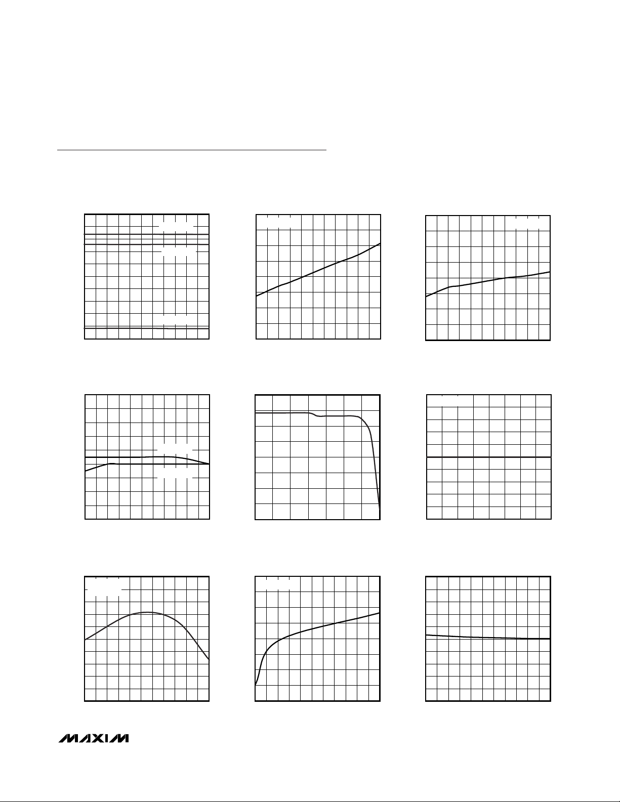
Typical Operating Characteristics
(VCC= +15V, V+ = 3V to 5.5V, RT= 10kΩ, CT= 3.3nF, V
REF
= COMP = open, C
REF
= 0.1µF, VFB= 2V, CS = AGND = PGND = 0V.
Typical values are at TA= +25°C, unless otherwise noted.)
BOOTSTRAP UVLO vs. TEMPERATURE
10
9
8
7
6
(V)
5
CC
V
4
3
2
1
0
-40 125
TEMPERATURE (°C)
VCC RISING
VCC FALLING
HYSTERESIS
1109565 80-10 5 20 35 50-25
MAX16807 toc01
41
VCC = 7.5V
39
37
35
(μA)
33
CC
I
31
29
27
25
-40 -10 5 20-25 35 50 9580 11065 125
REFERENCE VOLTAGE
5.08
vs. TEMPERATURE
5.06
5.04
5.02
I
5.00
(V)
REF
V
4.98
4.96
4.94
4.92
4.90
-40 -10 5 20-25 35 50 9580 11065 125
TEMPERATURE (°C)
REF
I
REF
= 1mA
= 20mA
MAX16807 toc04
(V)
V
REF
vs. REFERENCE LOAD CURRENT
5.05
5.00
4.95
4.90
4.85
4.80
4.75
4.70
4.65
02010 30 40 50 60 70
STARTUP CURRENT
vs. TEMPERATURE
TEMPERATURE (°
REFERENCE VOLTAGE
I
(mA)
REF
OPERATING SUPPLY CURRENT
vs. TEMPERATURE AFTER STARTUP
5.1
4.9
MAX16807 toc02
4.7
4.5
(mA)
4.3
CC
I
4.1
3.9
3.7
3.5
-40 -10 5 20-25 35 50 9580 11065 125
C
5.000
I
REF
4.998
4.996
MAX16807 toc05
4.994
4.992
4.990
REF
4.988
4.986
4.984
4.982
4.980
10 14 1612 18 20 22 24 26
= fSW = 300kHz)
(f
OSC
TEMPERATURE
REFERENCE VOLTAGE
vs. SUPPLY VOLTAGE
= 1mA
VCC (V)
CT = 560pF
MAX16807 toc03
MAX16807 toc06
OSCILLATOR FREQUENCY (f
vs. TEMPERATURE
550
RT = 3.65kΩ
540
= 560pF
C
T
530
520
510
500
490
480
OSCILLATOR FREQUENCY (kHz)
470
460
450
-40 -10 5-25 203550658095110125
TEMPERATURE (°C)
OSC
)
OSCILLATOR RT/CT DISCHARGE CURRENT
vs. TEMPERATURE
8.04
V
= 2V
RT/CT
8.02
MAX16807 toc07
8.00
7.98
7.96
7.94
DISCHARGE CURRENT (mA)
T
7.92
/C
T
R
7.90
7.88
-40 -10 5 20-25 35 50 9580 11065 125
TEMPERATURE (°C)
MAX16807 toc08
CURRENT-SENSE TRIP THRESHOLD
vs. TEMPERATURE
0.40
0.38
0.36
0.34
0.32
0.30
0.28
CS THRESHOLD (V)
0.26
0.24
0.22
0.20
-40 -10 5 20-25 35 50 9580 11065 125
TEMPERATURE (°C)
MAX16807 toc09
Page 8

MAX16807/MAX16808
Integrated 8-Channel LED Drivers with
Switch-Mode Boost and SEPIC Controller
8 _______________________________________________________________________________________
Typical Operating Characteristics (continued)
(VCC= +15V, V+ = 3V to 5.5V, RT= 10kΩ, CT= 3.3nF, V
REF
= COMP = open, C
REF
= 0.1µF, VFB= 2V, CS = AGND = PGND = 0V.
Typical values are at TA= +25°C, unless otherwise noted.)
TIMING RESISTANCE
OUT IMPEDANCE vs. TEMPERATURE
vs. OSCILLATOR FREQUENCY
MAX16807 toc10
(Ω)
DS_ON
R
5.0
I
4.8
4.6
4.4
4.2
4.0
3.8
3.6
3.4
3.2
3.0
2.8
2.6
2.4
2.2
2.0
-40 125
1000
CT = 1nF
100
(kΩ)
10
T
R
CT = 10nF
CT = 4.7nF
1
CT = 3.3nF
CT = 2.2nF
0.1
10k 10M
CT = 560pF
CT = 220pF
1M100k
FREQUENCY (Hz)
CT = 100pF
(R
DS_ON
= 100mA
SOURCE
TEMPERATURE (°C)
PMOS DRIVER)
OUT IMPEDANCE vs. TEMPERATURE
(R
I
SINK
DS_ON
= 200mA
TEMPERATURE (°C)
10
9
MAX16807 toc11
1109565 80-10 5 20 35 50-25
8
7
6
(Ω)
5
DS_ON
R
4
3
2
1
0
-40 -10 5 20-25 35 50 9580 11065 125
NMOS DRIVER)
MAX16807 toc12
PROPAGATION DELAY FROM CURRENT-LIMIT
COMPARATOR TO OUT vs. TEMPERATURE
100
90
80
70
60
50
40
30
PROPAGATION DELAY (ns)
20
10
0
-40 -10 5 20-25 35 50 9580 11065 125
TEMPERATURE (°C)
MAX16807 toc13
ERROR-AMPLIFIER OPEN-LOOP GAIN
140
120
100
80
60
GAIN (dB)
40
20
0
-20
0.01
SUPPLY CURRENT
vs. OSCILLATOR FREQUENCY
7.0
CT = 100pF
6.5
6.0
5.5
5.0
(mA)
4.5
CC
I
4.0
3.5
3.0
2.5
2.0
20 220 320 420120 520 620 720 920820 1020
TA = +125°C
TA = -40°C
FREQUENCY (kHz)
AND PHASE vs. FREQUENCY
GAIN
FREQUENCY (Hz)
MAX16807 toc14
PHASE
1M100k1k 10k10 1001
SUPPLY CURRENT vs. SUPPLY VOLTAGE
(INTERFACE IDLE, ALL OUTPUTS OFF, R
2.00
MAX16807 toc16
1.95
1.90
SUPPLY CURRENT (mA)
1.85
1.80
COMP VOLTAGE LEVEL TO TURN
OFF DEVICE vs. TEMPERATURE
10
-15
-40
-65
-90
-115
-140
-165
-190
100M
10M
TA = +125°C
3.0 5.5
SUPPLY VOLTAGE (V)
2.3
2.2
2.1
2.0
(V)
1.9
COMP
V
1.8
PHASE (DEGREES)
1.7
1.6
1.5
TA = +85°C
TA = -40°C
-40 -10 5 20-25 35 50 9580 11065 125
TEMPERATURE (°C)
= 720Ω)
SET
TA = +25°C
5.04.54.03.5
VCC = 15V
MAX16807 toc15
MAX16807 toc17
Page 9

MAX16807/MAX16808
Integrated 8-Channel LED Drivers with
Switch-Mode Boost and SEPIC Controller
_______________________________________________________________________________________
9
_______________________________________________________________________________________
9
Typical Operating Characteristics (continued)
(VCC= +15V, V+ = 3V to 5.5V, RT= 10kΩ, CT= 3.3nF, V
REF
= COMP = open, C
REF
= 0.1µF, VFB= 2V, CS = AGND = PGND = 0V.
Typical values are at TA= +25°C, unless otherwise noted.)
SUPPLY CURRENT vs. SUPPLY VOLTAGE
(INTERFACE IDLE, ALL OUTPUTS OFF, R
3.70
TA = +125°C
3.65
3.60
SUPPLY CURRENT (mA)
3.55
3.50
3.0 5.5
TA =-40°C
SUPPLY VOLTAGE (V)
TA = +85°C
SUPPLY CURRENT vs. SUPPLY VOLTAGE
(INTERFACE IDLE, ALL OUTPUTS ON, R
25
22
19
16
SUPPLY CURRENT (mA)
13
10
3.0 4.03.5 4.5 5.0 5.5
TA = +125°C
TA = -40°C
SUPPLY VOLTAGE (V)
TA = +85°C
TA = +25°C
= 360Ω)
SET
TA = +25°C
5.04.54.03.5
SET
= 360Ω)
MAX16807 toc18
MAX16807 toc20
SUPPLY CURRENT vs. SUPPLY VOLTAGE
(INTERFACE IDLE, ALL OUTPUTS ON, R
20
TA = +125°C
17
14
11
SUPPLY CURRENT (mA)
8
5
3.0 4.03.5 4.5 5.0 5.5
TA = -40°C
SUPPLY VOLTAGE (V)
TA = +85°C
TA = +25°C
= 720Ω)
SET
MAX16807 toc19
OUT_ CURRENT vs. OUT_ VOLTAGE
= 720Ω, V+ = 3.3V)
(R
30
25
20
15
10
OUT_ CURRENT (mA)
5
0
0 1.0 1.50.5 2.0 2.5 3.0
SET
MAX16807 toc21
TA = -40°C
TA = +25°C
TA = +85°C
TA = +125°C
OUT_ VOLTAGE (V)
OUT_ CURRENT vs. OUT_ VOLTAGE
= 360Ω, V+ = 3.3V)
(R
60
50
40
30
20
OUT_ CURRENT (mA)
10
0
SET
MAX16807 toc22
TA = -40°C
TA = +25°C
TA = +85°C
TA = +125°C
0 1.0 1.50.5 2.0 2.5 3.0
OUT_ VOLTAGE (V)
OUT_ CURRENT vs. OUT_ VOLTAGE
= 720Ω, V+ = 5.0V)
(R
30
25
20
15
10
OUT_ CURRENT (mA)
5
0
0 1.0 1.50.5 2.0 2.5 3.0
SET
TA = -40°C
TA = +25°C
TA = +85°C
TA = +125°C
OUT_ VOLTAGE (V)
MAX16807 toc23
Page 10

MAX16807/MAX16808
Integrated 8-Channel LED Drivers with
Switch-Mode Boost and SEPIC Controller
10 ______________________________________________________________________________________
Typical Operating Characteristics (continued)
(VCC= +15V, V+ = 3V to 5.5V, RT= 10kΩ, CT= 3.3nF, V
REF
= COMP = open, C
REF
= 0.1µF, VFB= 2V, CS = AGND = PGND = 0V.
Typical values are at TA= +25°C, unless otherwise noted.)
48
49
50
51
52
3.0 4.03.5 4.5 5.0 5.5
OUT_ CURRENT vs. SUPPLY VOLTAGE V+
(R
SET
= 360Ω, V
OUT
= 2V)
MAX16807 toc26
SUPPLY VOLTAGE (V)
OUT_ CURRENT (mA)
TA = +125°C
TA = -40°C
TA = +25°C
TA = +85°C
OUT_ CURRENT vs. SET RESISTANCE
(V+ = 5.0V)
MAX16807 toc27
R
SET
(kΩ)
OUT_ CURRENT (mA)
4321
10
20
30
40
50
0
05
0
20
10
40
30
50
60
OUT_ CURRENT vs. OUT_ VOLTAGE
(R
SET
= 360Ω, V+ = 5.0V)
MAX16807 toc24
OUT_ VOLTAGE (V)
OUT_ CURRENT (mA)
0 1.0 1.50.5 2.0 2.5 3.0
TA = +25°C
TA = -40°C
TA = +85°C
TA = +125°C
24.0
24.5
25.0
25.5
26.0
3.0 4.03.5 4.5 5.0 5.5
OUT_ CURRENT vs. SUPPLY VOLTAGE V+
(R
SET
= 720Ω, V
OUT
= 2V)
MAX16807 toc25
SUPPLY VOLTAGE (V)
OUT_ CURRENT (mA)
TA = +125°C
TA = -40°C
TA = +25°C
TA = +85°C
Page 11

MAX16807/MAX16808
Integrated 8-Channel LED Drivers with
Switch-Mode Boost and SEPIC Controller
______________________________________________________________________________________ 11
Detailed Description
The MAX16807/MAX16808 LED drivers include an
internal switch-mode controller that can be used as
boost or buck-boost (SEPIC) converters to generate the
voltage necessary to drive the multiple strings of LEDs.
These devices incorporate an integrated low-side driver, a programmable oscillator (20kHz to 1MHz), an
error amplifier, a low-voltage (300mV) current sense for
higher efficiency, and a 5V reference to power up
external circuitry (see Figures 1a, 1b, and 1c).
The MAX16807/MAX16808 LED drivers include a 4-wire
serial interface and a current-mode PWM controller to
generate the necessary voltage for driving eight opendrain, constant-current-sinking output ports. The drivers
use current-sensing feedback circuitry (not simple current mirrors) to ensure very small current variations over
the full allowed range of output voltage (see the
Typical
Operating Characteristics
). The 4-wire serial interface
comprises an 8-bit shift register and an 8-bit transparent latch. The shift register is written through a clock
input, CLK, and a data input, DIN, and the data propagates to a data output, DOUT. The data output allows
multiple drivers to be cascaded and operated together.
The contents of the 8-bit shift register are loaded into
the transparent latch through a latch-enable input, LE.
The latch is transparent to the shift register outputs
when high and latches the current state on the falling
edge of LE. Each driver output is an open-drain, constant-current sink that should be connected to the cath-
Pin Description
PIN NAME FUNCTION
1, 13, 28 N.C. No Connection. Not internally connected. Leave unconnected.
2 AGND Analog Ground
3 OUT MOSFET Driver Output OUT. Connects to the gate of the external n-channel MOSFET.
4V
5 REF 5V Reference Output. Bypass REF to AGND with a 0.1µF ceramic capacitor.
6–9 OUT4–OUT7 LED Driver Outputs. OUT4–OUT7 are open-drain, constant-current-sinking outputs rated for 36V.
10 OE
11 DOUT
12 SET LED Current Setting. Connect R
14 V+ LED Driver Positive Supply Voltage. Bypass V+ to PGND with a 0.1µF ceramic capacitor.
15, 16 PGND Power Ground
17 DIN Serial-Data Input
18 CLK Serial-Clock Input
19 LE
20–23 OUT0–OUT3 LED Driver Outputs. OUT0–OUT3 are open-drain, constant-current-sinking outputs rated for 36V.
24 COMP Error-Amplifier Output
25 FB Error-Amplifier Inverting Input
26 CS PWM Controller Current-Sense Input
27 RTCT
—EP
CC
Power-Supply Input. Bypass VCC to AGND with a 0.1µF ceramic capacitor or a parallel combination
of a 0.1µF and a higher value ceramic capacitor.
Active-Low Output Enable Input. Drive OE low to PGND to enable the OUT0–OUT7. Drive OE high to
disable OUT0–OUT7.
Serial-Data Output. Data is clocked out of the 8-bit internal shift register to DOUT on CLK’s rising
edge.
from SET to PGND to set the LED current.
SET
Latch-Enable Input. Data is loaded transparently from the internal shift register(s) to the output
latch(es) while LE is high. Data is latched into the output latch(es) on LE’s falling edge, and retained
while LE is low.
PWM Controller Timing Resistor/Capacitor Connection. A resistor R
capacitor C
Exposed Paddle. Connect to the ground plane for improved power dissipation. Do not use as the
only ground connection for the part.
from RTCT to AGND set the oscillator frequency.
T
from RTCT to REF and a
T
Page 12

MAX16807/MAX16808
Integrated 8-Channel LED Drivers with
Switch-Mode Boost and SEPIC Controller
12 ______________________________________________________________________________________
ode of a string of LEDs connected in series. The constant-current capability is up to 55mA per output, set
for all 8 outputs by an external resistor, R
SET
. The
devices can operate in a stand-alone mode (see the
Typical Operating Circuits
.)
The MAX16808 includes circuitry that automatically
detects open-circuit LEDs. Fault status is loaded into the
serial-interface shift register when LE goes high and is
automatically shifted out on DOUT when the next data
transmission is shifted in. The number of channels can be
expanded by using the MAX6970 and MAX6971 family in
conjunction with the MAX16807 and MAX16808.
Figure 1a. Internal Block Diagram (MAX16807)
AGND
CS
FB
COMP
MAX16807
VEA
REFERENCE
2.5V
DELAY
300mV
REG_OK
I
LIM
PREREG
2R
5V
R
THERMAL
SHUTDOWN
CPWM
CLK
UVLO
EN_REF
BG
SNS
OSC
V
DD
5V REG
VOLTAGE
DIVIDER
Q
VOLTAGE-
DIVIDER
26.5V
V
CC
S
Q
R
V
REF
OUT
RTCT
CC
CLK
DIN
LE
OE
THERMAL
SHUTDOWN
D0 D1 D2 D3 D4 D5 D6 D7
D0 D1 D2 D3 D4 D5 D6 D7
D0 D1 D2 D3 D4 D5 D6 D7
OUT0
SERIAL-TO-PARALLEL SHIFT REGISTER
CONSTANT-CURRENT SINK
OUT1
OUT2
OUTPUT LATCHES
OUT3
OUT4
OUT5
OUT6
OUT7
POWER-ON
RESET
V+
CURRENT
REFERENCE
PGND
DOUT
V+
SET
Page 13

MAX16807/MAX16808
Integrated 8-Channel LED Drivers with
Switch-Mode Boost and SEPIC Controller
______________________________________________________________________________________ 13
Figure 1b. Internal Block Diagram (MAX16808)
AGND
COMP
CLK
CLK
UVLO
EN_REF
BG
SNS
OSC
V
DD
5V REG
VOLTAGE
DIVIDER
Q
VOLTAGE-
DIVIDER
V
CC
26.5V
REF
V
CC
S
Q
R
OUT
RTCT
MAX16808
REFERENCE
2.5V
DELAY
300mV
CS
FB
VEA
REG_OK
I
LIM
PREREG
5V
THERMAL
SHUTDOWN
CPWM
2R
R
SERIAL-TO-PARALLEL SHIFT REGISTER
DIN
LE
OE
THERMAL
SHUTDOWN
D0 D1 D2 D3 D4 D5 D6 D7
D0 D1 D2 D3 D4 D5 D6 D7
D0 D1 D2 D3 D4 D5 D6 D7
OUT0
OUT1
OUTPUT LATCHES
CONSTANT-CURRENT SINK
OPEN LED FAULT DETECTION
OUT2
OUT3
OUT4
OUT5
OUT6
OUT7
POWER-ON
RESET
V+
CURRENT
REFERENCE
PGND
DOUT
V+
SET
Page 14

MAX16807/MAX16808
Integrated 8-Channel LED Drivers with
Switch-Mode Boost and SEPIC Controller
14 ______________________________________________________________________________________
Switch-Mode Controller
Current-Mode Control Loop
The advantages of current-mode control over voltagemode control are twofold. First, there is the feed-forward characteristic brought on by the controller’s ability
to adjust for variations in the input voltage on a cycleby-cycle basis. Second, the stability requirements of
the current-mode controller are reduced to that of a single pole system unlike the double pole in the voltagemode control scheme. The MAX16807/MAX16808 use
a current-mode control loop where the output of the
error amplifier is compared to the current-sense voltage
(VCS). When the current-sense signal is lower than the
inverting input of the CPWM comparator, the output of
the comparator is low and the switch is turned on at
each clock pulse. When the current-sense signal is
higher than the inverting input of the CPWM comparator, the output is high and the switch is turned off.
Undervoltage Lockout (UVLO)
The turn-on supply voltage for the MAX16807/
MAX16808 is 8.4V (typ). Once V
CC
reaches 8.4V, the
reference powers up. There is a 0.8V of hysteresis from
the turn-on voltage to the UVLO threshold. Once V
CC
reaches 8.4V, the MAX16807/MAX16808 operate with
V
CC
down to 7.6V (typ). Once VCCgoes below 7.6V,
the device is in UVLO. When in UVLO, the quiescent
supply current into VCCfalls back to 32µA (typ), and
OUT and REF are pulled low.
MOSFET Driver
OUT drives an external n-channel MOSFET and swings
from AGND to VCC. Ensure that VCCremains below the
absolute maximum VGSrating of the external MOSFET.
OUT is a push-pull output with the on-resistance of the
pMOS typically 3.5Ω and the on-resistance of the
nMOS typically 4.5Ω. The driver can source 2A and
sink 1A typically. This allows for the MAX16807/
MAX16808 to quickly turn on and off high gate-charge
MOSFETs. Bypass V
CC
with one or more 0.1µF ceramic
capacitors to AGND, placed close to the V
CC
pin. The
average current sourced to drive the external MOSFET
depends on the total gate charge (QG) and operating
frequency of the converter. The power dissipation in the
MAX16807/MAX16808 is a function of the average output drive current (I
DRIVE
). Use the following equation to
calculate the power dissipation in the device due to
I
DRIVE
:
I
DRIVE
= (QGx fSW)
PD = (I
DRIVE
+ ICC) x V
CC
where ICCis the operating supply current. See the
Typical Operating Characteristics
for the operating
supply current at a given frequency.
Error Amplifier
The MAX16807/MAX16808 include an internal error
amplifier. The inverting input is at FB and the noninverting input is internally connected to a 2.5V reference.
Set the output voltage using a resistive divider between
output of the converter V
OUT
, FB, and AGND. Use the
following formula to set the output voltage:
where V
FB
= 2.5V.
Oscillator
The oscillator frequency is programmable using an
external capacitor and a resistor at RTCT (see RTand
CTin the
Typical Operating Circuits
). RTis connected
from RTCT to the 5V reference (REF), and CTis connected from RTCT to AGND. REF charges CTthrough
RTuntil its voltage reaches 2.8V. CTthen discharges
through an 8.3mA internal current sink until CT’s voltage
reaches 1.1V, at which time CTis allowed to charge
through RTagain. The oscillator’s period is the sum of
the charge and discharge times of CT. Calculate the
charge time as follows:
tC= 0.57 x RTx C
T
where tCis in seconds, RT in ohms (Ω), and CTin
Farads (F).
The discharge time is then:
tD= (RTx CTx 1000) / [(4.88 x RT) - (1.8 x 1000)]
Figure 1c. OUT_ Driver Internal Diagram
V+
68W/L
1.23
R
1.23V
EST
W/L
995R
R
PGNDSET
OUT_
R
1
⎞
1
xV
⎟
⎠
R
2
V
OUT FB
⎛
=+
⎜
⎝
Page 15

MAX16807/MAX16808
Integrated 8-Channel LED Drivers with
Switch-Mode Boost and SEPIC Controller
______________________________________________________________________________________ 15
where tDis in seconds, RT in ohms (Ω), and CTin
Farads (F).
The oscillator frequency is then:
Reference Output
REF is a 5V reference output that can source 20mA.
Bypass REF to AGND with a 0.1µF capacitor.
Current Limit
The MAX16807/MAX16808 include a fast current-limit
comparator to terminate the on cycle during an overload or a fault condition. The current-sense resistor,
RCS, connected between the source of the external
MOSFET and AGND, sets the current limit. The CS
input has a voltage trip level (VCS) of 0.3V. Use the following equation to calculate RCS:
I
P-P
is the peak current that flows through the MOSFET.
When the voltage produced by this current (through the
current-sense resistor) exceeds the current-limit comparator threshold, the MOSFET driver (OUT) turns the
switch off within 60ns. In most cases, a small RC filter is
required to filter out the leading-edge spike on the sense
waveform. Set the time constant of the RC filter at 50ns.
Buck-Boost (SEPIC) Operation
Figure 2 shows a buck-boost application circuit using
the MAX16807/MAX16808 in a stand-alone mode of
operation. SEPIC topology is necessary when the total
forward voltage of the LEDs in a string is such that
V
OUT
can be below or above VIN.
Figure 2. Buck-Boost (SEPIC) Configuration
f
OSC
1
tt
=+
()
CD
V
IN
L1
C1
Q
D
C
L2
V
=
CS
I
PP
−
R
CS
V
OUT
OUT
R1
LEDs
OUT CS AGND COMP
V
CC
V+
PGND
DIN
LE
CLK
DOUT
OE
SET
REF
C
REF
3V TO 5.5V
C
IN
C
BYP
EXTERNAL
CLOCK INPUT
EXTERNAL
DIM INPUT
R
SET
R
CS
MAX16807
MAX16808
R
T
C
C2
C
C1
R
C1
R2
FB
OUT0
OUT1
OUT2
OUT3
OUT4
OUT5
OUT6
OUT7
RTCT
C
T
Page 16

MAX16807/MAX16808
Integrated 8-Channel LED Drivers with
Switch-Mode Boost and SEPIC Controller
16 ______________________________________________________________________________________
LED Driver
4-Wire Interface
The MAX16807/MAX16808 also operate in a standalone mode (see the
Typical Operating Circuits
). For
use with a microcontroller, the MAX16807/MAX16808
feature a 4-wire serial interface using DIN, CLK, LE, OE
inputs and DOUT as a data output. This interface is
used to write the LED channels’ data to the MAX16807/
MAX16808. The serial-interface data word length is 8
bits, D0–D7. See Figure 3.
The functions of the five interface pins are as follows:
DIN is the serial-data input, and must be stable when it
is sampled on the rising edge of CLK. Data is shifted in
MSB first. This means that data bit D7 is clocked in first,
followed by 7 more data bits, finishing with the LSB, D0.
CLK is the serial-clock input that shifts data at DIN into
the MAX16807/MAX16808’s 8-bit shift register on its rising edge.
LE is the latch enable input of the MAX16807/
MAX16808 that transfers data from the 8-bit shift register to its 8-bit output latch (transparent latch). The data
is latched on the falling edge of LE (Figure 4). The
fourth input (OE) provides output-enable control of the
output drivers. When OE is driven high, the outputs
(OUT0–OUT7) are forced to high impedance without
altering the contents of the output latches. Driving OE
low enables the outputs to follow the state of the output
latches. OE is independent of the operation of the serial
interface operation. Data can be shifted into the serialinterface shift register and latched, regardless of the
state of OE. DOUT is the serial-data output that shifts
data out from the MAX16807/MAX16808’s 8-bit shift
register on the rising edge of CLK. Data at DIN propagates through the shift register and appears at DOUT
eight clock cycles later. Table 1 shows the 4-wire serial-interface truth table.
Table 1. 4-Wire Serial-Interface Truth Table
L = Low Logic Level
H = High Logic Level
X = Don’t Care
P = Present State (Shift Register)
R = Previous State (Latched)
SERIAL
DATA
INPUT
DIN
CLOCK
INPUT
SHIFT REGISTER CONTENTS
CLK D0 D1 D2 … Dn-1 Dn LE D0 D1 D2 … Dn-1 Dn OE D0 D1 D2 … Dn-1 Dn
LOAD
INPUT
LATCH CONTENTS
BLANKING
INPUT
OUTPUT CONTENTS
CURRENT AT OUT_
H H R0 R1 … Rn-2 Rn-1
L L R0 R1 … Rn-2 Rn-1
X R0 R1 R2 … Rn-1 Rn
X X X … X X L R0 R1 R2 … Rn-1 Rn
P0 P1 P2 … Pn-1 Pn H P0 P1 P2 … Pn-1 Pn L P0 P1 P2 … Pn-1 Pn
XXX…X X H LLL… L L
Page 17

MAX16807/MAX16808
Integrated 8-Channel LED Drivers with
Switch-Mode Boost and SEPIC Controller
______________________________________________________________________________________ 17
LED Fault Detection (MAX16808)
The MAX16808 includes circuitry that detects open-circuit LEDs automatically. An open-circuit fault occurs
when an output is sinking current less than approximately 50% of the programmed current flows. Open circuits are checked just after the falling edge of OE. The
fault data is latched on the rising edge of LE and is
shifted out when new LED data is loaded into the output latches from the shift register. If one or more output
ports are detected with an open-circuit fault, the D6
and D5 bits of DOUT go high. If no open-circuit faults
are detected, D6 and D5 are set to low. The data in the
other 6 bit positions in DOUT are not altered. Fault status is shifted out on DOUT for the first two rising edges
of the clock after the falling edge of LE (see Figure 5).
LE is normally taken high after all 8 bits of new LED
Figure 3. 4-Wire Serial-Interface Timing Diagram
Figure 4. LE and CLK to OUT_ Timing
Figure 5. Fault Timing
CLK
DOUT
DIN
LE
t
t
CL
CH
t
DH
t
DS
D7
t
OE
OEW
t
CP
D0
t
DO
t
LW
t
LS
D7
OUT_
LE
OUT_
LE
OUT_
CLK
OUT_
t
LRF
t
LRR
t
CRF
t
OEF
t
f
80%
20%
t
OER
t
r
OE
CLK
OUT_
t
CRR
LE
CLK
DOUT
D5
D6
D7
FAULT STATUS BITS
D4
Page 18

MAX16807/MAX16808
Integrated 8-Channel LED Drivers with
Switch-Mode Boost and SEPIC Controller
18 ______________________________________________________________________________________
data have been clocked into the shift register(s), and
then DOUT outputs data bit D7. A typical fault-detecting application tests all the shifted out data. Bits D0–D4
and D7 are checked against the originally transmitted
data to check data-link integrity. Bits D5 and D6 are
checked first to see that they contain the same data
(validating the status), and second, whether faults are
reported or not by the actual logic level.
Selecting External Component
R
SET
to Set LED Output Current
The MAX16807/MAX16808 use an external resistor,
R
SET
, to set the LED current for outputs OUT0–OUT7.
The minimum allowed value of R
SET
is 330Ω, which
sets the output currents to 55mA. The maximum
allowed value of R
SET
is 5kΩ (I
OUT_
= 3.6mA) and max-
imum allowed capacitance at SET is 100pF.
Use the following formula to set the output current:
where I
OUT_
is the desired output current in milliamps
and the value for R
SET
is in ohms.
Overtemperature Cutoff
The MAX16807/MAX16808 contain an internal temperature sensor that turns off all outputs when the die temperature exceeds +165°C. The outputs are enabled again
when the die temperature drops below +140°C. Register
contents are not affected, so when a driver is overdissipating, the external symptom is the load LEDs cycling on
and off as the driver repeatedly overheats and cools,
alternately turning itself off and then back on again.
Stand-Alone Operation
In stand-alone operation, the MAX16807/MAX16808
does not use the 4-wire interface (see the
Typical
Operating Circuits
). Connect DIN and LE to V+ provide
at least 8 external clock pulses to CLK to enable 8 outputs. This startup pulse sequence can be provided
either using an external clock or the PWM signal. The
external clock can also be generated using the signal
at RTCT and an external comparator.
LED Dimming
PWM Dimming
All the output channels can be dimmed simultaneously
by applying a PWM signal (50Hz to 30kHz) to OE. This
allows for a wide range of dimming up to a 5000:1 ratio.
Each channel can be independently turned on and off
using a 4-wire serial interface. The dimming is proportional to the PWM duty cycle.
LED Current Amplitude Adjustment
Using an analog or digital potentiometer as R
SET
allows
for LED current amplitude adjustment and linear dimming.
Computing Power Dissipation
Use the following equation to estimate the upper limit
power dissipation (PD) for the MAX16807/MAX16808:
where:
V+ = supply voltage
I+ = operating supply current
DUTY = PWM duty cycle applied to OE
V
OUTi
= MAX16807/MAX16808 port output voltage
when driving load LED(s)
I
OUTi
= LED drive current programmed by R
SET
PD = power dissipation.
PCB Layout Guidelines
Careful PCB layout is critical to achieve low switching
losses and clean, stable operation. Use a multilayer
board whenever possible for better noise immunity.
Protect sensitive analog grounds by using a star
ground configuration. Minimize ground noise by connecting AGND, PGND, the input bypass-capacitor
ground lead, and the output-filter ground lead to a single point (star ground configuration). Also, minimize
trace lengths to reduce stray capacitance, trace resistance, and radiated noise. The trace between the output voltage-divider and the FB pin must be kept short,
as well as the trace between AGND and PGND.
R
=
SET
18 000
I
,
_
OUT
i
i
∑
==0
7
OUTi CC CC
OUTi
⎤
⎥
⎥
⎦
PD DUTY x V x I V x I V x I
( ) ( )
=+++
⎡
⎢
⎢
⎣
+
Page 19

MAX16807/MAX16808
Integrated 8-Channel LED Drivers with
Switch-Mode Boost and SEPIC Controller
______________________________________________________________________________________ 19
Pin Configuration
Chip Information
PROCESS: BiCMOS
TOP VIEW
N.C.
AGND
OUT
OUT4
+
1
2
3
4
MAX16807
CC
MAX16808
REF
5
6
7
TSSOP-EP
28
N.C.
27
RTCT
26
CS
25
FBV
24
COMP
23
OUT3
OUT2OUT5
22
218 OUT1OUT6
209 OUT0OUT7
1910 LEOE
1811 CLKDOUT
1712 DINSET
1613 PGNDN.C.
1514 PGNDV+
Page 20

MAX16807/MAX16808
Integrated 8-Channel LED Drivers with
Switch-Mode Boost and SEPIC Controller
20 ______________________________________________________________________________________
Typical Operating Circuits (continued)
V
IN
3V TO 5.5V
C
IN
C
BYP
R
SET
L
Q
R
CS
OUT CS AGND COMP
V
CC
V+
PGND
REF
MAX16807
MAX16808
R
T
LE
DIN
CLK
DOUT
OE
SET
C
REF
D
C
C1
RTCT
C
T
V
OUT
C
OUT
C
C2
R
C1
FB
OUT0
OUT1
OUT2
OUT3
OUT4
OUT5
OUT6
OUT7
R1
R2
STAND-ALONE OPERATION
LEDs
Page 21

MAX16807/MAX16808
Integrated 8-Channel LED Drivers with
Switch-Mode Boost and SEPIC Controller
Maxim cannot assume responsibility for use of any circuitry other than circuitry entirely embodied in a Maxim product. No circuit patent licenses are
implied. Maxim reserves the right to change the circuitry and specifications without notice at any time.
Maxim Integrated Products, 120 San Gabriel Drive, Sunnyvale, CA 94086 408-737-7600 ____________________
21
© 2007 Maxim Integrated Products is a registered trademark of Maxim Integrated Products, Inc.
Heaney
Package Information
(The package drawing(s) in this data sheet may not reflect the most current specifications. For the latest package outline information,
go to www.maxim-ic.com/packages
.)
Revision History
Pages changed at Rev 1: 1, 21
XX XX
TSSOP 4.4mm BODY.EPS
PACKAGE OUTLINE, TSSOP, 4.40 MM BODY,
EXPOSED PAD
21-0108
1
E
1
 Loading...