

Page 1
General Description
The MAX15004A/B/MAX15005A/B high-performance,
current-mode PWM controllers operate at an automotive input voltage range from 4.5V to 40V (load dump).
The input voltage can go down as low as 2.5V after
startup if VCCis supplied by an external bias voltage.
The controllers integrate all the building blocks necessary for implementing fixed-frequency isolated/nonisolated power supplies. The general-purpose boost,
flyback, forward, and SEPIC converters can be
designed with ease around the MAX15004/MAX15005.
The current-mode control architecture offers excellent
line-transient response and cycle-by-cycle current limit
while simplifying the frequency compensation.
Programmable slope compensation simplifies the
design further. A fast 60ns current-limit response time,
low 300mV current-limit threshold makes the controllers
suitable for high-efficiency, high-frequency DC-DC converters. The devices include an internal error amplifier
and 1% accurate reference to facilitate the primary-side
regulated, single-ended flyback converter or nonisolated converters.
An external resistor and capacitor network programs
the switching frequency from 15kHz to 500kHz (1MHz for
the MAX15005A/B). The MAX15004A/B/MAX15005A/B
provide a SYNC input for synchronization to an external
clock. The maximum FET-driver duty cycle for the
MAX15004A/B is 50%. The maximum duty cycle can be
set on the MAX15005A/B by selecting the right combination of RT and CT.
The input undervoltage lockout (ON/OFF) programs the
input-supply startup voltage and can be used to shutdown the converter to reduce the total shutdown current down to 10µA. Protection features include
cycle-by-cycle and hiccup current limit, output overvoltage protection, and thermal shutdown.
The MAX15004A/B/MAX15005A/B are available in
space-saving 16-pin TSSOP and thermally enhanced
16-pin TSSOP-EP packages. All devices operate over
the -40°C to +125°C automotive temperature range.
Applications
Automotive
Vacuum Fluorescent Display (VFD) Power
Supply
Isolated Flyback, Forward, Nonisolated SEPIC,
Boost Converters
Features
♦ Wide 4.5V to 40V Operating Input Voltage Range
♦ Operates Down to 2.5V (with Bootstrapped V
CC
Bias)
♦ Current-Mode Control
♦ Low 300mV, 5% Accurate Current-Limit Threshold
Voltage
♦ Internal Error Amplifier with 1% Accurate Reference
♦ RC Programmable 4% Accurate Switching
Frequency
♦ Switching Frequency Adjustable from 15kHz to
500kHz (1MHz for the MAX15005A/B)
♦ External Frequency Synchronization
♦ 50% (MAX15004) or Adjustable (MAX15005)
Maximum Duty Cycle
♦ Programmable Slope Compensation
♦ 10µA Shutdown Current
♦ Cycle-by-Cycle and Hiccup Current-Limit
Protection
♦ Overvoltage and Thermal Shutdown Protection
♦ -40°C to +125°C Automotive Temperature Range
♦ 16-Pin TSSOP or 16-Pin Thermally Enhanced
TSSOP-EP Packages
♦ AEC-Q100 Qualified
MAX15004/MAX15005
4.5V to 40V Input Automotive
Flyback/Boost/SEPIC Power-Supply Controllers
________________________________________________________________
Maxim Integrated Products
1
Ordering Information
19-0723; Rev 3; 1/11
For pricing, delivery, and ordering information, please contact Maxim Direct at 1-888-629-4642,
or visit Maxim’s website at www.maxim-ic.com.
Note: All devices are specified over the -40°C to +125°C
temperature range.
+
Denotes a lead(Pb)-free/RoHS-compliant package.
/V denotes an automotive qualified part.
*
EP = Exposed pad.
Pin Configurations appear at end of data sheet.
EVALUATION KIT
AVAILABLE
PART PIN-PACKAGE MAX DUTY CY CLE
MAX15004AAUE+ 16 TSSOP-EP* 50%
MAX15004AAUE/V+ 16 TSSOP-EP* 50%
MAX15004BAUE+ 16 TSSOP 50%
MAX15004BAUE/V+ 16 TSSOP 50%
MAX15005AAUE+ 16 TSSOP-EP* Programmable
MAX15005AAUE/V+ 16 TSSOP-EP* Programmable
MAX15005BAUE+ 16 TSSOP Programmable
MAX15005BAUE/V+ 16 TSSOP Programmable
Page 2
MAX15004/MAX15005
4.5V to 40V Input Automotive
Flyback/Boost/SEPIC Power-Supply Controllers
2 _______________________________________________________________________________________
ABSOLUTE MAXIMUM RATINGS
ELECTRICAL CHARACTERISTICS
(VIN= 14V, CIN= 0.1μF, C
VCC
= 0.1μF // 1μF, C
REG5
= 1μF, V
ON/OFF
= 5V, CSS= 0.01μF, C
SLOPE
= 100pF, RT = 13.7kΩ, CT =
560pF, V
SYNC
= V
OVI
= VFB= VCS= 0V, COMP = unconnected, OUT = unconnected. TA= TJ= -40°C to +125°C, unless otherwise
noted. Typical values are at T
A
= +25°C. All voltages are referenced to PGND, unless otherwise noted.) (Note 1) (Figure 5)
Stresses beyond those listed under “Absolute Maximum Ratings” may cause permanent damage to the device. These are stress ratings only, and functional
operation of the device at these or any other conditions beyond those indicated in the operational sections of the specifications is not implied. Exposure to
absolute maximum rating conditions for extended periods may affect device reliability.
IN to SGND.............................................................-0.3V to +45V
IN to PGND.............................................................-0.3V to +45V
ON/OFF to SGND ........................................-0.3V to (V
IN
+ 0.3V)
OVI, SLOPE, RTCT, SYNC, SS, FB, COMP,
CS to SGND.........................................-0.3V to (V
REG5
+ 0.3V)
V
CC
to PGND..........................................................-0.3V to +12V
REG5 to SGND .........................................................-0.3V to +6V
OUT to PGND.............................................-0.3V to (V
CC
+ 0.3V)
SGND to PGND .....................................................-0.3V to +0.3V
V
CC
Sink Current (clamped mode).....................................35mA
OUT Current (< 10μs transient) ..........................................±1.5A
Continuous Power Dissipation* (T
A
= +70°C)
16-Pin TSSOP-EP (derate 21.3mW/°C
above +70°C)..............................................................1702mW
16-Pin TSSOP (derate 9.4mW/°C above +70°C) ..........754mW
Operating Junction Temperature Range...........-40°C to +125°C
Junction Temperature......................................................+150°C
Storage Temperature Range .............................-60°C to +150°C
Lead Temperature (soldering, 10s) .................................+300°C
Soldering Temperature (reflow) .......................................+260°C
*
As per JEDEC51 Standard, Multilayer Board.
PARAMETER SYMBOL CONDITIONS MIN TYP MAX UNITS
POWER SUPPLY
Input Supply Range V
Operating Supply Current I
ON/OFF CONTROL
Input-Voltage Threshold V
Input-Voltage Hysteresis V
Input Bias Current I
Shutdown Current I
INTERNAL 7.4V LDO (VCC)
Output (VCC) Voltage Set Point V
Line Regulation VIN = 8V to 40V 1 mV/V
UVLO Threshold Voltage V
UVLO Hysteresis V
Dropout Voltage VIN = 4.5V, I
Output Current Limit I
Internal Clamp Voltage V
INTERNAL 5V LDO (REG5)
IN
Q
ON
HYST-ON
B-ON/OFFVON/OFF
SHDN
VCC
UVLO-VCCVCC
HYST-UVLO
VCC-ILIMIVCC
VCC-CLAMPIVCC
VIN = 40V, f
V
ON/OFF
V
ON/OFF
I
VCC
OSC
rising 1.05 1.23 1.40 V
= 40V 0.5 μA
= 0V 10 20 μA
= 0 to 20mA (sourcing) 7.15 7.4 7.60 V
rising 3.15 3.5 3.75 V
VCC
sourcing 45 mA
= 30mA (sinking) 10.0 10.4 10.8 V
= 150kHz 2 3.1 mA
= 20mA (sourcing) 0.25 0.5 V
4.5 40.0 V
75 mV
500 mV
Output (REG5) Voltage Set Point V
Line Regulation VCC = 5.5V to 10V 2 mV/V
Dropout Voltage VCC = 4.5V, I
Output Current Limit I
REG5
REG5-ILIMIREG5
VCC = 7.5V, I
sourcing 32 mA
= 0 to 15mA (sourcing) 4.75 4.95 5.05 V
REG5
= 15mA (sourcing) 0.25 0.5 V
REG5
Page 3
MAX15004/MAX15005
4.5V to 40V Input Automotive
Flyback/Boost/SEPIC Power-Supply Controllers
_______________________________________________________________________________________ 3
ELECTRICAL CHARACTERISTICS (continued)
(VIN= 14V, CIN= 0.1μF, C
VCC
= 0.1μF // 1μF, C
REG5
= 1μF, V
ON/OFF
= 5V, CSS= 0.01μF, C
SLOPE
= 100pF, RT = 13.7kΩ, CT =
560pF, V
SYNC
= V
OVI
= VFB= VCS= 0V, COMP = unconnected, OUT = unconnected. TA= TJ= -40°C to +125°C, unless otherwise
noted. Typical values are at T
A
= +25°C. All voltages are referenced to PGND, unless otherwise noted.) (Note 1) (Figure 5)
PARAMETER SYMBOL CONDITIONS MIN TYP MAX UNITS
OSCILLATOR (RTCT)
Oscillator Frequency Range f
RTCT Peak Trip Level V
RTCT Valley Trip Level V
RTCT Discharge Current I
Oscillator Frequency Accuracy
(Note 2)
Maximum PWM Duty Cycle
(Note 3)
Minimum On-Time t
SYNC Lock-In Frequency Range
(Note 4)
SYNC High-Level Voltage V
SYNC Low-Level Voltage V
SYNC Input Current I
SYNC Minimum Input Pulse Width 50 ns
ERROR AMPLIFIER/SOFT-START
Soft-Start Charging Current I
SS Reference Voltage V
SS Threshold for HICCUP Enable VSS rising 1.1 V
FB Regulation Voltage V
FB Input Offset Voltage V
FB Input Current VFB = 0 to 1.5V -300 +300 nA
COMP Sink Current I
OSC
TH,RTCT
TL,RTCT
DIS,RTCTVRTCT
f
f
OSC
OSC
= 2 x f
OUT
= f
for MAX15005A/B
OUT
for MAX15004A/B,
= 2V 1.30 1.33 1.36 mA
RT = 13.7kΩ, CT = 4.7nF,
f
(typ) = 18kHz
OSC
RT = 13.7kΩ, CT = 560pF,
f
(typ) = 150kHz
OSC
RT = 21kΩ, CT = 100pF,
(typ) = 500kHz
f
OSC
RT = 7kΩ, CT = 100pF,
f
(typ) = 1MHz
OSC
15 1000 kHz
0.55 x V
0.1 x V
REG5
REG5
-4 +4
-4 +4
-5 +5
-7 +7
MAX15004A/B 50
D
MAX
ON-MIN
IH-SYNC
IL-SYNC
SYNC
SS
SS
REF-FB
MAX15005A/B,
RT = 13.7kΩ, CT = 560pF,
f
(typ) = 150kHz
OSC
78.5 80 81.5
VIN = 14V 110 170 ns
RT = 13.7kΩ, CT = 560pF,
f
(typ) = 150kHz
OSC
102 200 %f
2V
V
= 0 to 5V -0.5 +0.5 μA
SYNC
VSS = 0V 8 15 21 μA
1.215 1.228 1.240 V
COMP = FB,
= -500μA to +500μA
I
COMP
1.215 1.228 1.240 V
COMP = 0.25V to 4.5V,
= -500μA to +500μA,
I
OS-FB
COMP-SINKVFB
COMP
V
SS
= 0 to 1.5V
= 1.5V, V
= 0.25V 3 5.5 mA
COMP
-5 +5 mV
0.8 V
V
V
%
%
OSC
Page 4
MAX15004/MAX15005
4.5V to 40V Input Automotive
Flyback/Boost/SEPIC Power-Supply Controllers
4 _______________________________________________________________________________________
ELECTRICAL CHARACTERISTICS (continued)
(VIN= 14V, CIN= 0.1μF, C
VCC
= 0.1μF // 1μF, C
REG5
= 1μF, V
ON/OFF
= 5V, CSS= 0.01μF, C
SLOPE
= 100pF, RT = 13.7kΩ, CT =
560pF, V
SYNC
= V
OVI
= VFB= VCS= 0V, COMP = unconnected, OUT = unconnected. TA= TJ= -40°C to +125°C, unless otherwise
noted. Typical values are at T
A
= +25°C. All voltages are referenced to PGND, unless otherwise noted.) (Note 1) (Figure 5)
PARAMETER SYMBOL CONDITIONS MIN TYP MAX UNITS
COMP Source Current
COMP High Voltage V
COMP Low Voltage V
Open-Loop Gain A
Unity-Gain Bandwidth UGF
Phase Margin PM
COMP Positive Slew Rate SR+ 0.5 V/μs
COMP Negative Slew Rate SR- -0.5 V/μs
PWM COMPARATOR
Current-Sense Gain A
PWM Propagation Delay to OUT t
I
COMP-
SOURCE
OH-COMPVFB
OL-COMPVFB
EAMP
EAMP
EAMP
CS-PWM
PD-PWM
VFB = 1V, V
= 1V, I
COMP
COMP
= 1.5V, I
ΔV
COMP
/ΔV
CS
CS = 0.15V, from V
= 4.5V 1.3 2.8 mA
= 1mA (sourcing)
= 1mA (sinking) 0.1 0.25 V
COMP
(Note 5) 2.85 3 3.15 V/V
falling edge:
COMP
3V to 0.5V to OUT falling (excluding
V
REG5
- 0.5
V
REG5
- 0.2
100 dB
1.6 MHz
75 degrees
60 ns
leading-edge blanking time)
V
PWM Comparator Current-Sense
Leading-Edge Blanking Time
t
CS-BLANK
50 ns
CURRENT-LIMIT COMPARATOR
Current-Limit Threshold Voltage V
Current-Limit Input Bias Current I
ILIMIT Propagation Delay to OUT t
ILIM
B-CS
PD-ILIM
OUT= high, 0 ≤ VCS ≤ 0.3V -2 +2 μA
From CS rising above V
ILIM
(50mV
overdrive) to OUT falling (excluding
290 305 317 mV
60 ns
leading-edge blanking time)
ILIM Comparator Current-Sense
Leading-Edge Blanking Time
Number of Consecutive ILIMIT
Events to HICCUP
t
CS-BLANK
50 ns
7
HICCUP Timeout 512
SLOPE COMPENSATION (Note 6)
Slope Capacitor Charging
Current
Slope Compensation C
Slope Compensation Tolerance
(Note 2)
Slope Compensation Range
I
SLOPE
V
= 100mV 9.8 10.5 11.2 μA
SLOPE
= 100pF 25 mV/μs
SLOPE
C
= 100pF -4 +4 %
SLOPE
C
= 22pF 110
SLOPE
= 1000pF 2.5
C
SLOPE
Clock
periods
mV/μs
Page 5
MAX15004/MAX15005
4.5V to 40V Input Automotive
Flyback/Boost/SEPIC Power-Supply Controllers
_______________________________________________________________________________________ 5
ELECTRICAL CHARACTERISTICS (continued)
(VIN= 14V, CIN= 0.1μF, C
VCC
= 0.1μF // 1μF, C
REG5
= 1μF, V
ON/OFF
= 5V, CSS= 0.01μF, C
SLOPE
= 100pF, RT = 13.7kΩ, CT =
560pF, V
SYNC
= V
OVI
= VFB= VCS= 0V, COMP = unconnected, OUT = unconnected. TA= TJ= -40°C to +125°C, unless otherwise
noted. Typical values are at T
A
= +25°C. All voltages are referenced to PGND, unless otherwise noted.) (Note 1) (Figure 5)
Note 1: 100% production tested at +125°C. Limits over the temperature range are guaranteed by design.
Note 2: Guaranteed by design; not production tested.
Note 3: For the MAX15005A/B, D
MAX
depends upon the value of RT. See Figure 3 and the
Oscillator Frequency/External
Synchronization
section.
Note 4: The external SYNC pulse triggers the discharge of the oscillator ramp. See Figure 2. During external SYNC, D
MAX
= 50% for
the MAX15004A/B; for the MAX15005A/B, there is a shift in D
MAX
with f
SYNC/fOSC
ratio (see the
Oscillator Frequency/
External Synchronization
section).
Note 5: The parameter is measured at the trip point of latch, with 0 ≤ V
CS
≤ 0.3V, and FB = COMP.
Note 6: Slope compensation = (2.5 x 10
-9
)/C
SLOPE
mV/μs. See the
Applications Information
section.
PARAMETER SYMBOL CONDITIONS MIN TYP MAX UNITS
OUTPUT DRIVER
Driver Output Impedance
Driver Peak Output Current I
OVERVOLTAGE COMPARATOR
Overvoltage Comparator Input
Threshold
Overvoltage Comparator
Hysteresis
Overvoltage Comparator Delay TD
OVI Input Current I
THERMAL SHUTDOWN
Shutdown Temperature T
Thermal Hysteresis T
R
OUT-N
R
OUT-P
OUT-PEAK
V
OV-TH
V
OV-HYST
OVI
OVI
SHDN
HYST
VCC = 8V (applied externally),
= 100mA (sinking)
I
OUT
VCC = 8V (applied externally),
= 100mA (sourcing)
I
OUT
C
= 10nF, sinking 1000
OUT
C
= 10nF, sourcing 750
OUT
V
rising 1.20 1.228 1.26 V
OVI
From OVI rising above 1.228V to OUT
falling, with 50mV overdrive
V
= 0 to 5V -0.5 +0.5 μA
OVI
Temperature rising 160
1.7 3.5
35
125 mV
1.6 μs
15
Ω
mA
o
C
o
C
Page 6
MAX15004/MAX15005
4.5V to 40V Input Automotive
Flyback/Boost/SEPIC Power-Supply Controllers
6 _______________________________________________________________________________________
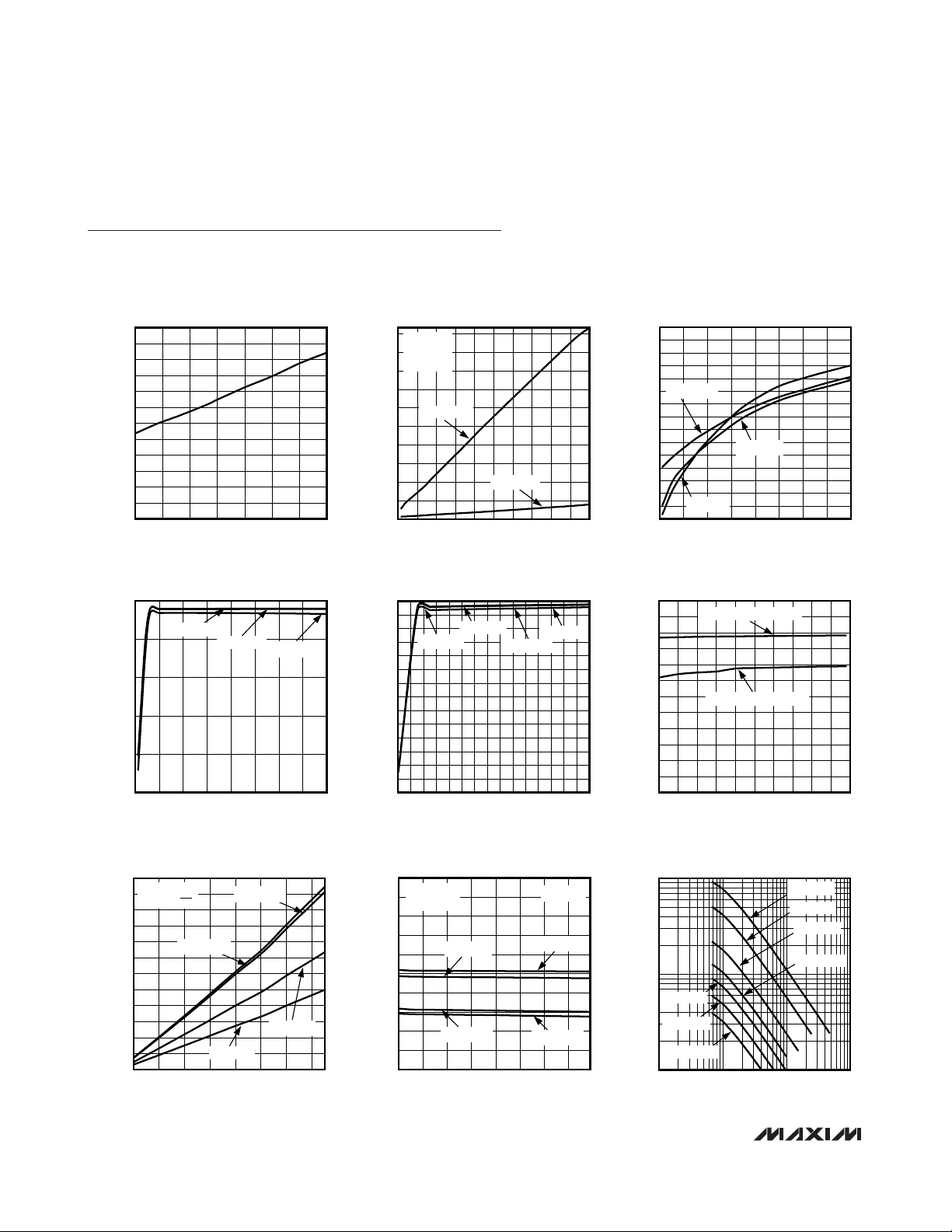
Typical Operating Characteristics
(VIN= 14V, CIN= 0.1μF, C
VCC
= 0.1μF // 1μF, C
REG5
= 1μF, V
ON/OFF
= 5V, CSS= 0.01μF, C
SLOPE
= 100pF, RT = 13.7kΩ,
CT = 560pF. TA = +25°C, unless otherwise noted.)
VIN UVLO HYSTERESIS
vs. TEMPERATURE
TEMPERATURE (°C)
V
IN
UVLO HYSTERESIS (mV)
MAX15004 toc01
-40 -15 10 35 60 85 110 135
0
10
20
30
40
50
60
70
80
90
100
110
120
VIN SUPPLY CURRENT (I
SUPPLY
)
vs. OSCILLATOR FREQUENCY (f
OSC
)
FREQUENCY (kHz)
V
IN
SUPPLY CURRENT (mA)
MAX15004 toc02
10 60 110 160 210 260 310 360 410 460 510
1
4
7
10
13
16
19
22
25
28
31
MAX15005
V
IN
= 14V
CT = 220pF
C
OUT
= 10nF
C
OUT
= 0nF
SHUTDOWN SUPPLY CURRENT
vs. SUPPLY VOLTAGE
SUPPLY VOLTAGE (V)
V
IN
SHUTDOWN SUPPLY CURRENT (μA)
MAX15004 toc03
5 1015202530354045
5
6
7
8
9
10
11
12
13
14
15
16
17
18
19
20
TA = +135°C
TA = -40°C
TA = +25°C
V
CC
OUTPUT VOLTAGE
vs. V
IN
SUPPLY VOLTAGE
VIN SUPPLY VOLTAGE (V)
V
CC
OUTPUT VOLTAGE (V)
MAX15004 toc04
5 1015202530354045
5.0
5.5
6.0
6.5
7.0
7.5
I
VCC
= 0mA
I
VCC
= 1mA
I
VCC
= 20mA
VCC CLAMP VOLTAGE
vs. V
CC
CURRENT SINK (I
VCC
)
VCC CURRENT SINK (mA)
V
CC
CLAMP VOLTAGE (V)
MAX15004 toc05
0 2 4 6 8 10 12 14 16 18 20 22 24 26 28 30
7.00
7.25
7.50
7.75
8.00
8.25
8.50
8.75
9.00
9.25
9.50
9.75
10.00
10.25
10.50
TA = +135°C
TA = -40°C
TA = +25°C
TA = +125°C
REG5 OUTPUT VOLTAGE
vs. V
CC
VOLTAGE
VCC VOLTAGE (V)
REG5 OUTPUT VOLTAGE (V)
MAX15004 toc06
5.5 6.0 6.5 7.0 7.5 8.0 8.5 9.0 9.5 10.0 10.5
4.700
4.725
4.750
4.775
4.800
4.825
4.850
4.875
4.900
4.925
4.950
4.975
5.000
I
REG5
= 1mA (SOURCING)
I
REG5
= 15mA (SOURCING)
REG5 DROPOUT VOLTAGE
vs. I
REG5
I
REG5
(mA)
REG5 LDO DROPOUT VOLTAGE (V)
MAX15004 toc07
0 2 4 6 8 10 12 14
0
0.03
0.05
0.08
0.10
0.13
0.15
0.18
0.20
0.23
0.25
0.28
0.30
TA = +135°C
TA = +25°C
TA = -40°C
TA = +125°C
VCC = 4.5
V
IN
= V
ON/OFF
OSCILLATOR FREQUENCY (f
OSC
)
vs. V
IN
SUPPLY VOLTAGE
VIN SUPPLY VOLTAGE (V)
OSCILLATOR FREQUENCY (kHz)
MAX15004 toc08
5.5 10.5 15.5 20.5 25.5 30.5 35.5 40.5 45.5
140
141
142
143
144
145
146
147
148
149
150
TA = +125°C
TA = -40°C
TA = +25°C
TA = +135°C
RT = 13.7kΩ
CT = 560pF
MAX15005
OSCILLATOR FREQUENCY (f
OSC
)
vs. RT/CT
RT (kΩ)
OSCILLATOR FREQUENCY (kHz)
MAX15004 toc09
1 10 100 1000
10
100
1000
CT = 220pF
CT = 1500pF
CT = 1000pF
CT = 560pF
CT = 2200pF
CT = 3300pF
CT = 100pF
Page 7
MAX15004/MAX15005
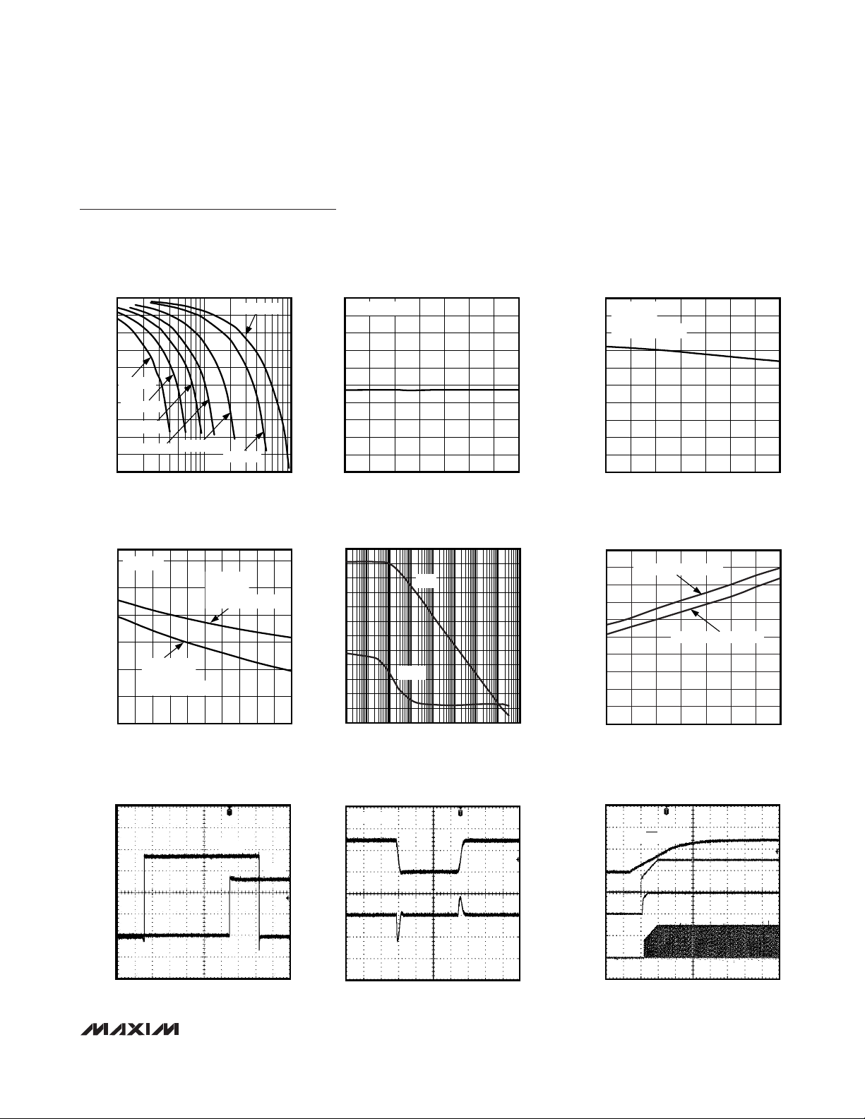
OVI TO OUT DELAY THROUGH
OVERVOLTAGE COMPARATOR
MAX15004 toc16
1μs/div
V
OUT
2V/div
V
OVI
500mV/div
V
OUT
V
OVI
DRIVER OUTPUT PEAK SOURCE
AND SINK CURRENT
MAX15004 toc17
400ns/div
V
OUT
5V/div
I
OUT
1A/div
C
OUT
= 10nF
POWER-UP SEQUENCE THROUGH V
IN
MAX15004 toc18
2ms/div
V
IN
10V/div
V
CC
5V/div
REG5
5V/div
V
OUT
5V/div
V
ON/OFF
= 5V
4.5V to 40V Input Automotive
Flyback/Boost/SEPIC Power-Supply Controllers
_______________________________________________________________________________________
7
Typical Operating Characteristics (continued)
(VIN= 14V, CIN= 0.1μF, C
VCC
= 0.1μF // 1μF, C
REG5
= 1μF, V
ON/OFF
= 5V, CSS= 0.01μF, C
SLOPE
= 100pF, RT = 13.7kΩ,
CT = 560pF. TA = +25°C, unless otherwise noted.)
MAX15005 MAXIMUM DUTY CYCLE
vs. OUTPUT FREQUENCY (f
100
95
90
85
80
CT = 3300pF
75
70
CT = 2200pF
65
CT = 1500pF
MAXIMUM DUTY CYCLE (%)
60
CT = 1000pF
55
50
10 100 1000
CT = 560pF
OUTPUT FREQUENCY (kHz)
MAXIMUM DUTY CYCLE
vs. f
SYNC/fOSC
80
MAX15005
75
70
65
C
= 220pF
60
MAXIMUM DUTY CYCLE (%)
55
50
RTCT
= 10kΩ
R
RTCT
= f
= 418kHz
f
OSC
OUT
1.0 1.1 1.2 1.3 1.4 1.5 1.6 1.7 1.8 1.9 2.0
f
SYNC/fOSC
CT = 220pF
RATIO
CT = 560pF
RT = 10kΩ
= f
f
OSC
OUT
RATIO
CT = 100pF
)
OUT
MAX15004 toc10
MAXIMUM DUTY CYCLE (%)
MAX15004 toc13
= 180kHz
GAIN (dB)
55
54
53
52
51
50
49
48
47
46
45
110
100
90
80
70
60
50
40
30
20
10
0
-10
MAX15004 MAXIMUM DUTY CYCLE
vs. TEMPERATURE
f
= 75kHz
OUT
-40 -15 10 35 60 85 110 135
TEMPERATURE (°C)
ERROR AMPLIFIER OPEN-LOOP GAIN
AND PHASE vs. FREQUENCY
GAIN
PHASE
0.1 1 10 100 1k 10k 100k 1M 10M
FREQUENCY (Hz)
MAX15004 toc14
MAX15004 toc11
340
300
260
220
180
140
100
60
MAX15005 MAXIMUM DUTY CYCLE
85
CT = 560pF
83
RT = 13.7kΩ
f
OSC
81
79
77
75
73
71
MAXIMUM DUTY CYCLE (%)
69
67
65
-40 -15 10 35 60 85 110 135
CS-TO-OUT DELAY vs. TEMPERATURE
100
90
80
70
60
50
40
PHASE (DEGREES)
30
CS-TO-OUT DELAY (ns)
20
10
0
-40 -15 10 35 60 85 110 135
vs. TEMPERATURE
= f
= 150kHz
OUT
TEMPERATURE (°C)
VCS OVERDRIVE = 50mV
VCS OVERDRIVE = 190mV
TEMPERATURE (°C)
MAX15004 toc12
MAX15004 toc15
Page 8
MAX15004/MAX15005
4.5V to 40V Input Automotive
Flyback/Boost/SEPIC Power-Supply Controllers
8 _______________________________________________________________________________________
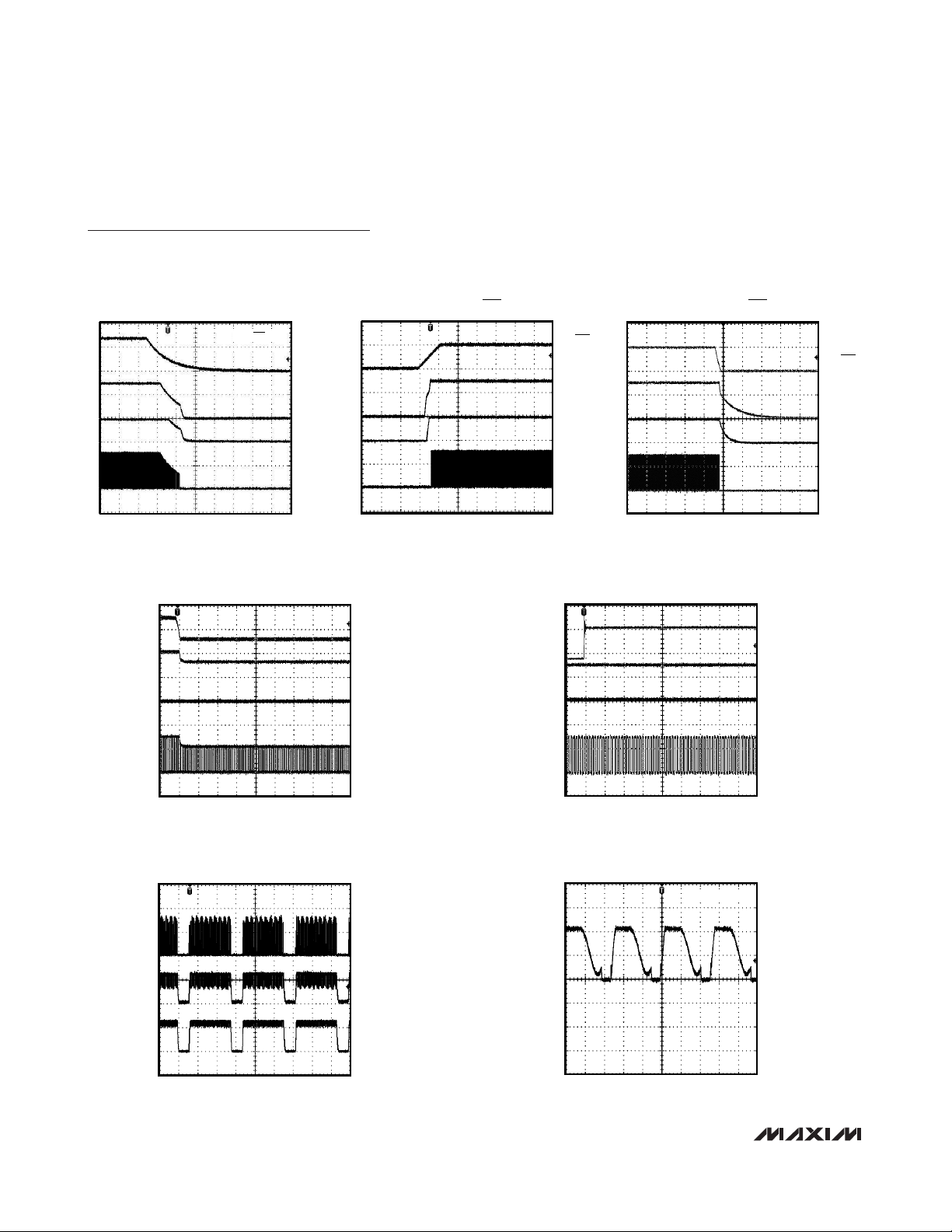
Typical Operating Characteristics (continued)
(VIN= 14V, CIN= 0.1μF, C
VCC
= 0.1μF // 1μF, C
REG5
= 1μF, V
ON/OFF
= 5V, CSS= 0.01μF, C
SLOPE
= 100pF, RT = 13.7kΩ,
CT = 560pF. TA = +25°C, unless otherwise noted.)
HICCUP MODE FOR FLYBACK CIRCUIT
(FIGURE 7)
MAX15004 toc24
10ms/div
V
CS
200mV/div
V
ANODE
1V/div
I
SHORT
500mA/div
DRAIN WAVEFORM IN
FLYBACK CONVERTER (FIGURE 7)
MAX15004 toc25
4μs/div
10V/div
I
LOAD
= 10mA
LINE TRANSIENT FOR VIN STEP
FROM 14V TO 5.5V
MAX15004 toc22
100μs/div
V
IN
10V/div
V
CC
5V/div
REG5
5V/div
V
OUT
5V/div
LINE TRANSIENT FOR VIN STEP
FROM 14V TO 40V
MAX15004 toc23
100μs/div
V
IN
20V/div
V
CC
5V/div
REG5
5V/div
V
OUT
5V/div
POWER-DOWN SEQUENCE THROUGH V
MAX15004 toc19
V
= 5V
ON/OFF
IN
V
IN
10V/div
V
CC
5V/div
REG5
5V/div
V
OUT
5V/div
POWER-UP SEQUENCE
THROUGH ON/OFF
MAX15004 toc20
ON/OFF
5V/div
V
CC
5V/div
REG5
5V/div
V
OUT
5V/div
POWER-DOWN SEQUENCE
THROUGH ON/OFF
MAX15004 toc21
ON/OFF
5V/div
V
CC
5V/div
REG5
5V/div
V
OUT
5V/div
4ms/div
1ms/div
400ms/div
Page 9
MAX15004/MAX15005
4.5V to 40V Input Automotive
Flyback/Boost/SEPIC Power-Supply Controllers
_______________________________________________________________________________________ 9
Pin Description
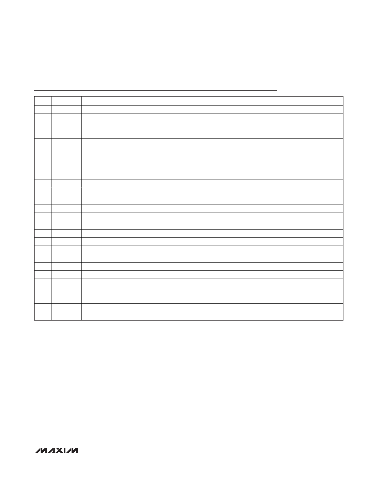
PIN NAME FUNCTION
1 IN Input Power Supply. Bypass IN with a minimum 0.1μF ceramic capacitor to PGND.
ON/OFF Input. Connect ON/OFF to IN for always-on operation. To externally program the UVLO threshold of the
2 ON/OFF
3 OVI
4 SLOPE
5 N.C. No Connection. Not internally connected.
6 RTCT
7 SGND Signal Ground. Connect SGND to SGND plane.
8 SYNC External-Clock Synchronization Input. Connect SYNC to SGND when not using an external clock.
9 SS Soft-Start Capacitor Input. Connect a capacitor from SS to SGND to set the soft-start time interval.
10 FB Internal Error-Amplifier Inverting Input. The noninverting input is internally connected to SS.
11 COMP Error-Amplifier Output. Connect the frequency compensation network between FB and COMP.
12 CS
13 REG5 5V Low-Dropout Regulator Output. Bypass REG5 with a 1μF ceramic capacitor to SGND.
14 PGND Power Ground. Connect PGND to the power ground plane.
15 OUT Gate Driver Output. Connect OUT to the gate of the external n-channel MOSFET.
16 V
—EP
CC
IN supply, connect a resistive divider between IN, ON/OFF, and SGND. Pull ON/OFF to SGND to disable the
controller.
Overvoltage Comparator Input. Connect a resistive divider between the output of the power supply, OVI, and
SGND to set the output overvoltage threshold.
Programmable Slope Compensation Capacitor Input. Connect a capacitor (C
of slope compensation.
Slope compensation = (2.5 x 10
Oscillator-Timing Network Input. Connect a resistor from RTCT to REG5 and a capacitor from RTCT to SGND to
set the oscillator frequency (see the Oscillator Frequency/External Synchronization section).
Current-Sense Input. The current-sense signal is compared to a signal proportional to the error-amplifier output
voltage.
7.4V Low-Dropout Regulator Output—Driver Power Source. Bypass VCC with 0.1μF and 1μF or higher ceramic
capacitors to PGND.
Exposed Pad (MAX15004A/MAX15005A only). Connect EP to the SGND plane to improve thermal performance.
Do not use the EP as an electrical connection.
-9
) / C
SLOPE
mV/μs with C
SLOPE
in farads.
) to SGND to set the amount
SLOPE
Page 10

MAX15004/MAX15005
4.5V to 40V Input Automotive
Flyback/Boost/SEPIC Power-Supply Controllers
10 ______________________________________________________________________________________
Functional Diagram
IN
ON/OFF
1
1.228V
2
ON/OFF
COMP
THERMAL
SHUTDOWN
OFF
PREREGULATOR
REFERENCE
OFF
7.4V LDO
REG
3.5V
UVLO
UVB
MAX15004A/B
MAX15005A/B
10.5V
30mA
CLAMP
DRIVER
V
CC
16
V
CC
15
OUT
14
PGND
OVI
SLOPE
RTCT
SGND
SYNC
3
1.228V
4
6
7
8
OV-COMP
SLOPE
COMPENSATION
OSCILLATOR
CLK
SET
RESET
OVRLD
RESET
SS_OK
7
CONSECUTIVE
EVENTS
COUNTER
ILIMIT
COMP
PWM-
COMP
1.228V
REF-AMP
0.3V
2R
UVB
EAMP
13
5V LDO
REG
50ns
LEAD
DELAY
R
REG5
12
CS
11
COMP
10
FB
9
SS
OVRLD
Page 11

MAX15004/MAX15005
4.5V to 40V Input Automotive
Flyback/Boost/SEPIC Power-Supply Controllers
______________________________________________________________________________________ 11
Detailed Description
The MAX15004A/B/MAX15005A/B are high-performance, current-mode PWM controllers for wide inputvoltage range isolated/nonisolated power supplies.
These controllers are for use as general-purpose boost,
flyback, and SEPIC controllers. The input voltage range
of 4.5V to 40V makes it ideal in automotive applications
such as vacuum fluorescent display (VFD) power supplies. The internal low-dropout regulator (VCCregulator) enables the MAX15004A/B/MAX15005A/B to
operate directly from an automotive battery input. The
input operating range can be as low as 2.5V when an
external source (e.g. bootstrap winding output) is
applied at the VCCinput. The 2.5V to 40V input voltage
range allows device operation from cold crank to automotive load dump.
The undervoltage lockout (ON/OFF) allows the devices
to program the input-supply startup voltage and ensures
predictable operation during brownout conditions.
The devices contain two internal regulators, VCCand
REG5. The V
CC
regulator output voltage is set at 7.4V
and REG5 regulator output voltage at 5V ±2%. The
VCCoutput includes a 10.4V clamp that is capable of
sinking up to 30mA current. The input undervoltage
lockout (UVLO) circuit monitors the V
CC
voltage and
turns off the converter when the V
CC
voltage drops
below 3.5V (typ). See the
Internal Regulators VCCand
REG5
section for a method to obtain lower than 4.5V
input operation with the MAX15004/MAX15005.
An external resistor and capacitor network programs
the switching frequency from 15kHz to 500kHz. The
MAX15004A/B/MAX15005A/B provide a SYNC input for
synchronization to an external clock. The OUT (FET-driver output) duty cycle for the MAX15004A/B is 50%.
The maximum duty cycle can be set on MAX15005A/B
by selecting the right combination of RT and CT. The
RTCT discharge current is trimmed to 2%, allowing
accurate setting of the duty cycle for the MAX15005.
An internal slope-compensation circuit stabilizes the
current loop when operating at higher duty cycles and
can be programmed externally.
The MAX15004/MAX15005 include an internal error
amplifier with 1% accurate reference to regulate the
output in nonisolated topologies using a resistive
divider. The internal reference connected to the noninverting input of the error amplifier can be increased in a
controlled manner to obtain soft-start. A capacitor connected at SS to ground programs soft-start to reduce
inrush current and prevent output overshoot.
The MAX15004/MAX15005 include protection features
like hiccup current limit, output overvoltage, and thermal
shutdown. The hiccup current-limit circuit reduces the
power delivered to the electronics powered by the
MAX15004/MAX15005 converter during severe fault conditions. The overvoltage circuit senses the output using
the path different from the feedback path to provide
meaningful overvoltage protection. During continuous
high input operation, the power dissipation into the
MAX15004/MAX15005 could exceed its limit. Internal
thermal shutdown protection safely turns off the converter
when the junction heats up to 160°C.
Current-Mode Control Loop
The advantages of current-mode control overvoltagemode control are twofold. First, there is the feed-forward characteristic brought on by the controller’s ability
to adjust for variations in the input voltage on a cycleby-cycle basis. Secondly, the stability requirements of
the current-mode controller are reduced to that of a single-pole system unlike the double pole in voltage-mode
control.
The MAX15004/MAX15005 offer peak current-mode
control operation to make the power supply easy to
design with. The inherent feed-forward characteristic is
useful especially in an automotive application where the
input voltage changes fast during cold-crank and load
dump conditions. While the current-mode architecture
offers many advantages, there are some shortcomings.
For higher duty-cycle and continuous conduction mode
operation where the transformer does not discharge
during the off duty cycle, subharmonic oscillations
appear. The MAX15004/MAX15005 offer programmable
slope compensation using a single capacitor. Another
issue is noise due to turn-on of the primary switch that
may cause the premature end of the on cycle. The current-limit and PWM comparator inputs have leadingedge blanking. All the shortcomings of the
current-mode control are addressed in the MAX15004/
MAX15005, making it ideal to design for automotive
power conversion applications.
Internal Regulators VCCand REG5
The internal LDO converts the automotive battery voltage input to a 7.4V output voltage (VCC). The VCCoutput is set at 7.4V and operates in a dropout mode at
input voltages below 7.5V. The internal LDO is capable
of delivering 20mA current, enough to provide power to
internal control circuitry and the gate drive. The regulated VCCkeeps the driver output voltage well below the
absolute maximum gate voltage rating of the MOSFET
especially during the double battery and load dump
conditions. An auxiliary winding output can be fed to
the VCCoutput once the power supply is turned on.
The bootstrap winding is not necessary for proper
Page 12

MAX15004/MAX15005
4.5V to 40V Input Automotive
Flyback/Boost/SEPIC Power-Supply Controllers
12 ______________________________________________________________________________________
operation of the power supply; however, to reduce the
power dissipation of the internal LDO, it can be disabled by applying an external voltage higher than 7.4V
at VCC(LDO output). The LDO then stops drawing current from IN, thereby reducing the power dissipation in
the IC. The V
CC
voltage is clamped to 10.4V with 30mA
current sink in case there is a higher voltage at the bias
winding. This feature is useful in applications with continuous higher input voltage.
The second 5V LDO regulator from V
CC
to REG5 provides power to the internal control circuits. This LDO can
also be used to source 15mA of external load current.
Bypass VCCand REG5 with a parallel combination of
1μF and 0.1μF low-ESR ceramic capacitors. Additional
capacitors (up to 22μF) at VCCcan be used although
they are not necessary for proper operation of the
MAX15004/MAX15005.
Startup Operation/UVLO/ON/
OFF
The MAX15004A/B/MAX15005A/B feature two undervoltage lockouts (UVLO). The internal UVLO monitors
the VCC-regulator and turns on the converter once V
CC
rises above 3.5V. The internal UVLO circuit has about
0.5V hysteresis to avoid chattering during turn-on. Once
the power is on and the bootstrapped voltage feeds
VCC, IN voltage can drop below 4V. This feature provides operation at a cold-crank voltage as low as 2.5V.
An external undervoltage lockout can be achieved by
controlling the voltage at the ON/OFF input. The
ON/OFF input threshold is set at 1.23V (rising) with
75mV hysteresis.
Before any operation can commence, the ON/OFF voltage must exceed the 1.23V threshold.
Calculate R1 in Figure 1 by using the following formula:
where V
UVLO
is the ON/OFF’s 1.23V rising threshold,
and VONis the desired input startup voltage. Choose
an R2 value in the 100kΩ range. The UVLO circuits
keep the PWM comparator, ILIM comparator, oscillator,
and output driver shut down to reduce current consumption (see the
Functional Diagram
). The ON/OFF
input can be used to disable the MAX15004/MAX15005
and reduce the standby current to less than 20μA.
Soft-Start
The MAX15004/MAX15005 are provided with an externally adjustable soft-start function, saving a number of
external components. The SS is a 1.228V reference
bypass connection for the MAX15004A/B/MAX15005A/B
and also controls the soft-start period. At startup, after
V
IN
is applied and the UVLO thresholds are reached,
the device enters soft-start. During soft-start, 15μA is
sourced into the capacitor (CSS) connected from SS to
GND causing the reference voltage to ramp up slowly.
The HICCUP mode of operation is disabled during softstart. When VSSreaches 1.228V, the output as well as
the HICCUP mode become fully active. Set the soft-start
time (tSS) using following equation:
where tSSis in seconds and CSSis in farads.
The soft-start programmability is important to control the
input inrush current issue and also to avoid the
MAX15004/MAX15005 power supply from going into the
unintentional hiccup during the startup. The required
soft-start time depends on the topology used, currentlimit setting, output capacitance, and the load condition.
Oscillator Frequency/
External Synchronization
Use an external resistor and capacitor at RTCT to program the MAX15004A/B/MAX15005A/B internal oscillator
frequency from 15kHz to 1MHz. The MAX15004A/B output switching frequency is one-half the programmed
oscillator frequency with a 50% maximum duty-cycle
limit. The MAX15005A/B output switching frequency is
the same as the oscillator frequency. The RC network
connected to RTCT controls both the oscillator frequency
and the maximum duty cycle. The CT capacitor charges
and discharges from (0.1 x V
REG5
) to (0.55 x V
REG5
). It
charges through RT and discharges through an internal
trimmed controlled current sink. The maximum duty
cycle is inversely proportional to the discharge time
Figure 1. Setting the MAX15004A/B/MAX15005A/B
Undervoltage Lockout Threshold
⎛
V
R
112=−
ON
⎜
V
⎝
UVLO
⎞
R
×
⎟
⎠
MAX15004A/B
MAX15005A/B
t
=
SS
ON/OFF
1.23V
VC
123
15 10
×
.()
−
×
SS
6
A
()
V
IN
R1
R2
Page 13

MAX15004/MAX15005
4.5V to 40V Input Automotive
Flyback/Boost/SEPIC Power-Supply Controllers
______________________________________________________________________________________ 13
(t
DISCHARGE
). See Figures 3a and 3b for a coarse selection of capacitor values for a given switching frequency
and maximum duty cycle and then use the following
equations to calculate the resistor value to fine-tune the
switching frequency and verify the worst-case maximum
duty cycle.
where f
OSC
is the oscillator frequency, RT is a resistor
connected from RTCT to REG5, and CT is a capacitor
connected from RTCT to SGND. Verify that the oscillator frequency value meets the target. Above calculations could be repeated to fine-tune the switching
frequency.
The MAX15004A/B is a 50% maximum duty-cycle part,
while the MAX15005A/B is 100% maximum duty-cycle
part.
for the MAX15004A/B and
for the MAX15005A/B.
The MAX15004A/B/MAX15005A/B can be synchronized
using an external clock at the SYNC input. For proper
frequency synchronization, SYNC’s input frequency must
be at least 102% of the programmed internal oscillator
frequency. Connect SYNC to SGND when not using an
external clock. A rising clock edge on SYNC is interpreted as a synchronization input. If the SYNC signal is lost,
the internal oscillator takes control of the switching rate,
returning the switching frequency to that set by RC network connected to RTCT. This maintains output regulation even with intermittent SYNC signals.
Figure 2. Timing Diagram for Internal Oscillator vs. External SYNC and D
MAX
Behavior
D
MAX
=
f
OSC
t
CHARGE
=
CT
×=07.
2225
.()
VRTCT
××
3
−
ART V
××
Us
Use ThisEquation If f k+>
ns
−
≤+500
OSC
500....... HHz
OSC
f
=
OS
CC
t
CHARGE
RT
t
DISCHAR GE
⎧
⎪
tt
⎪
⎨
⎪
⎪
tt
⎩
1
+
CHARGE DISCHARGE
CHARG E DISCHA
1 33 10 3 375
(. ( ) ) . ()
................... ee This EquationIf f kHz
1
160
RRGE
MAX15004A/B (D
ff
OUT OSC
1
=
2
ff
=
OUT OSC
= 50%)
MAX
WITH SYNC
INPUT
WITHOUT
SYNC INPUT
RTCT
CLKINT
SYNC
OUT
D = 50%
MAX15005A/B (D
RTCT
CLKINT
SYNC
OUT
D = 81.25% D = 80%
MAX
= 81%)
WITH SYNC
INPUT
D = 50%
WITHOUT
SYNC INPUT
Page 14

MAX15004/MAX15005
4.5V to 40V Input Automotive
Flyback/Boost/SEPIC Power-Supply Controllers
14 ______________________________________________________________________________________
n-Channel MOSFET Driver
OUT drives the gate of an external n-channel MOSFET.
The driver is powered by the internal regulator (VCC),
internally set to approximately 7.4V. If an external voltage
higher than 7.4V is applied at VCC(up to 10V), it appears
as the peak gate drive voltage. The regulated VCCvoltage keeps the OUT voltage below the maximum gate
voltage rating of the external MOSFET. OUT can source
750mA and sink 1000mA peak current. The average current sourced by OUT depends on the switching frequency and total gate charge of the external MOSFET.
Error Amplifier
The MAX15004A/B/MAX15005A/B include an internal
error amplifier. The noninverting input of the error
amplifier is connected to the internal 1.228V reference
and feedback is provided at the inverting input. High
100dB open-loop gain and 1.6MHz unity-gain bandwidth allow good closed-loop bandwidth and transient
response. Moreover, the source and sink current capability of 2mA provides fast error correction during the
output load transient. For Figure 5, calculate the powersupply output voltage using the following equation:
where V
REF
= 1.228V. The amplifier’s noninverting input
is internally connected to a soft-start circuit that gradually increases the reference voltage during startup. This
forces the output voltage to come up in an orderly and
well-defined manner under all load conditions.
Slope Compensation
The MAX15004A/B/MAX15005A/B use an internal ramp
generator for slope compensation. The internal ramp
signal resets at the beginning of each cycle and slews
at the rate programmed by the external capacitor connected to SLOPE. The amount of slope compensation
needed depends on the downslope of the current
waveform. Adjust the MAX15004A/B/MAX15005A/B
slew rate up to 110mV/μs using the following equation:
where C
SLOPE
is the external capacitor at SLOPE in
farads.
Current Limit
The current-sense resistor (RCS), connected between
the source of the MOSFET and ground, sets the current
limit. The CS input has a voltage trip level (VCS) of
305mV. The current-sense threshold has 5% accuracy.
Set the current-limit threshold 20% higher than the peak
switch current at the rated output power and minimum
input voltage. Use the following equation to calculate
the value of R
S
:
where I
PRI
is the peak current that flows through the
MOSFET at full load and minimum VIN.
Figure 3a. MAX15005 Maximum Duty Cycle vs. Output
Frequency.
Figure 3b. Oscillator Frequency vs. RT/CT
MAX15005 MAXIMUM DUTY CYCLE
vs. OUTPUT FREQUENCY (f
100
95
90
85
80
CT = 3300pF
75
70
CT = 2200pF
65
CT = 1500pF
MAXIMUM DUTY CYCLE (%)
60
CT = 1000pF
55
50
10 100 1000
CT = 560pF
CT = 220pF
OUTPUT FREQUENCY (kHz)
)
OUT
CT = 100pF
OUT
⎛
=+
1
⎜
⎝
V
⎞
R
A
V
REF
⎟
R
⎠
B
OSCILLATOR FREQUENCY (f
1000
100
CT = 1500pF
CT = 2200pF
OSCILLATOR FREQUENCY (kHz)
CT = 3300pF
10
1 10 100 1000
vs. RT/CT
RT (kΩ)
OSC
CT = 100pF
CT = 220pF
CT = 560pF
CT = 1000pF
)
−
Slopecompensation mV s
25 10
()
μ=
.()
×
C
SLOPE
9
A
V
R
CS
=
S
I
PRI
Page 15

MAX15004/MAX15005
4.5V to 40V Input Automotive
Flyback/Boost/SEPIC Power-Supply Controllers
______________________________________________________________________________________ 15
When the voltage produced by this current (through the
current-sense resistor) exceeds the current-limit comparator threshold, the MOSFET driver (OUT) quickly terminates the on-cycle. In most cases, a short-time
constant RC filter is required to filter out the leadingedge spike on the sense waveform. The amplitude and
width of the leading edge depends on the gate capacitance, drain capacitance (including interwinding capacitance), and switching speed (MOSFET turn-on time).
Set the RC time constant just long enough to suppress
the leading edge. For a given design, measure the leading spike at the highest input and rated output load to
determine the value of the RC filter.
The low 305mV current-limit threshold reduces the
power dissipation in the current-sense resistor. The current-limit threshold can be further reduced by adding
an offset to the CS input from REG5 voltage. Do not
reduce the current-limit threshold below 150mV as it
may cause noise issues. See Figure 4. For a new value
of the current-limit threshold (V
CS-LOW
), calculate the
value of R1 using the following equation.
Applications Information
Boost Converter
The MAX15004A/B/MAX15005A/B can be configured
for step-up conversion. The boost converter output can
be fed back to VCC(see Figure 5) so that the controller
can function even during cold-crank input voltage
(≤ 2.5V). Use a Schottky diode (D
VIN
) in the VINpath to
avoid backfeeding the input source. A current-limiting
resistor (R
VCC
) is also needed from the boost converter
output to VCCdepending upon the boost converter output voltage. The total current sink into VCCmust be limited to 30mA. Use the equations in the following
sections to calculate R
VCC
, inductor (L
MIN
), input
capacitor (C
IN
), and output capacitor (C
OUT
) when
using the converter in boost operation.
Inductor Selection in Boost Configuration
Using the following equation, calculate the minimum
inductor value so that the converter remains in continuous mode operation at minimum output current (I
OMIN
).
where:
and
The higher value of I
OMIN
reduces the required inductance; however, it increases the peak and RMS currents
in the switching MOSFET and inductor. Use I
OMIN
from
10% to 25% of the full load current. The VDis the forward voltage drop of the external Schottky diode, D is
the duty cycle, and VDSis the voltage drop across the
external switch. Select the inductor with low DC resistance and with a saturation current (I
SAT
) rating higher
than the peak switch current limit of the converter.
Figure 4. Reducing Current-Sense Threshold
R
475
×
.
R
1
=
0 290
.
CS
V Low
−
−
CS
V
IN
VD
L
=
MIN
2f V I
IN
×× ×
OUT OUT OMIN
VVV
+
OUT D IN
D
=
VVVV
+ −
OUT D DS
2
××
η
−
REG5
MAX15004A/B
MAX15005A/B
0.3V
CURRENT-LIMIT
COMPARATOR
R1
C
CS
I (0.1 I ) to (0.25 I
N
R
CS
=× ×)
OMIN O O
R
S
Page 16

MAX15004/MAX15005
Input Capacitor Selection in Boost Configuration
The input current for the boost converter is continuous
and the RMS ripple current at the input capacitor is low.
Calculate the minimum input capacitor value and maximum ESR using the following equations:
where:
V
DS
is the total voltage drop across the external MOS-
FET plus the voltage drop across the inductor ESR. ΔI
L
is peak-to-peak inductor ripple current as calculated
above. ΔVQis the portion of input ripple due to the
capacitor discharge and ΔV
ESR
is the contribution due
to ESR of the capacitor. Assume the input capacitor ripple contribution due to ESR (ΔV
ESR
) and capacitor discharge (ΔVQ) is equal when using a combination of
ceramic and aluminum capacitors. During the converter turn-on, a large current is drawn from the input
source especially at high output to input differential.
The MAX15004/MAX15005 are provided with a programmable soft-start, however, a large storage capacitor at the input may be necessary to avoid chattering
due to finite hysteresis.
Output Capacitor Selection in Boost Configuration
For the boost converter, the output capacitor supplies
the load current when the main switch is on. The
required output capacitance is high, especially at higher
duty cycles. Also, the output capacitor ESR needs to be
low enough to minimize the voltage drop due to the ESR
while supporting the load current. Use the following
equations to calculate the output capacitor, for a specified output ripple. All ripple values are peak-to-peak.
4.5V to 40V Input Automotive
Flyback/Boost/SEPIC Power-Supply Controllers
16 ______________________________________________________________________________________
Figure 5. Application Schematic
V
IN
C
IN
C
REG5
0.1μF
13
RT
CT
C
FF
CF
RF
REG5
6
RTCT
11
COMP
10
FB
SLOPE
4
D
VIN
MAX15004A/B
MAX15005A/B
C
SLOPE
PGND
L
V
OUT
18V
RA
RB
OUT
D3
C
Q
RS
R
C
VIN
1μF
1
IN
16
V
CC
15
OUT
12
CS
SS
9
C
SS
VCC
D
VCC
C
VCC
4.7μF
R
CS
C
CS
ID
×
Δ
C
IN
ESR
=
=
L
4f V
××
V
Δ
ESR
I
Δ
Δ
OUT Q
L
(V V
−
))D
×
×
OUT
IN DS
I
=
Δ
L
Lf
Page 17

IOis the load current, ΔVQis the portion of the ripple due
to the capacitor discharge, and ΔV
ESR
is the contribution
due to the ESR of the capacitor. D
MAX
is the maximum
duty cycle at the minimum input voltage. Use a combination of low-ESR ceramic and high-value, low-cost aluminum capacitors for lower output ripple and noise.
Calculating Power Loss in Boost Converter
The MAX15004A/MAX15005A devices are available in
a thermally enhanced package and can dissipate up to
1.7W at +70°C ambient temperature. The total power
dissipation in the package must be limited so that the
junction temperature does not exceed its absolute maximum rating of +150°C at maximum ambient temperature; however, Maxim recommends operating the
junction at about +125°C for better reliability.
The average supply current (I
DRIVE-GATE
) required by
the switch driver is:
where Qgis total gate charge at 7.4V, a number available from MOSFET datasheet.
The supply current in the MAX15004A/B/MAX15005A/B
is dependent on the switching frequency. See the
Typical Operating Characteristics
to find the supply
current I
SUPPLY
of the MAX15004A/B/MAX15005A/B at
a given operating frequency. The total power dissipation (PT) in the device due to supply current (I
SUPPLY
)
and the current required to drive the switch (I
DRIVE-
GATE
) is calculated using following equation.
MOSFET Selection in Boost Converter
The MAX15004A/B/MAX15005A/B drive a wide variety of
n-channel power MOSFETs. Since VCClimits the OUT
output peak gate-drive voltage to no more than 11V, a
12V (max) gate voltage-rated MOSFET can be used without an additional clamp. Best performance, especially at
low-input voltages (5VIN), is achieved with low-threshold
n-channel MOSFETs that specify on-resistance with a
gate-source voltage (VGS) of 2.5V or less. When selecting
the MOSFET, key parameters can include:
1) Total gate charge (Qg).
2) Reverse-transfer capacitance or charge (C
RSS
).
3) On-resistance (R
DS(ON)
).
4) Maximum drain-to-source voltage (V
DS(MAX)
).
5) Maximum gate frequencies threshold voltage
(V
TH(MAX)
).
At high switching, dynamic characteristics (parameters 1
and 2 of the above list) that predict switching losses
have more impact on efficiency than R
DS(ON)
, which pre-
dicts DC losses. Q
g
includes all capacitances associat-
ed with charging the gate. The V
DS(MAX)
of the selected
MOSFET must be greater than the maximum output voltage setting plus a diode drop. The 10V additional margin
is recommended for spikes at the MOSFET drain due to
the inductance in the rectifier diode and output capacitor
path. In addition, Qghelps predict the current needed to
drive the gate at the selected operating frequency when
the internal LDO is driving the MOSFET.
Slope Compensation in Boost Configuration
The MAX15004A/B/MAX15005A/B use an internal ramp
generator for slope compensation to stabilize the current
loop when operating at duty cycles above 50%. It is
advisable to add some slope compensation even at lower
than 50% duty cycle to improve the noise immunity. The
slope compensations should be optimized because too
much slope compensation can turn the converter into the
voltage-mode control. The amount of slope compensation
required depends on the downslope of the inductor current when the main switch is off. The inductor downslope
depends on the input to output voltage differential of the
boost converter, inductor value, and the switching frequency. Theoretically, the compensation slope should be
equal to 50% of the inductor downslope; however, a little
higher than 50% slope is advised.
Use the following equation to calculate the required
compensating slope (mc) for the boost converter:
The internal ramp signal resets at the beginning of
each cycle and slews at the rate programmed by the
external capacitor connected to SLOPE. Adjust the
MAX15004A/B/MAX15005A/B slew rate up to 110mV/μs
using the following equation:
where C
SLOPE
is the external capacitor at SLOPE in
farads.
MAX15004/MAX15005
4.5V to 40V Input Automotive
Flyback/Boost/SEPIC Power-Supply Controllers
______________________________________________________________________________________ 17
V
Δ
ESR
C
OUT
ESR
=
I
O
ID
OMAX
=
Vf
Δ
×
×
QOUT
IQf
DRIVE GATE g OUT−
=×
PV I
INMAX SUPPLYTDRIVEGATE
()
I=× +
−
−
VVR
()10
mc
OUT IN S
=
−
××
L
2
3
mV s
()
μ
−
×
()μ
9
25 10
C
SLOPE
.
=
mc mV s
Page 18

MAX15004/MAX15005
4.5V to 40V Input Automotive
Flyback/Boost/SEPIC Power-Supply Controllers
18 ______________________________________________________________________________________
Selecting VCCResistor (R
VCC
)
The VCCexternal supply series resistor should be sized
to provide enough average current from V
OUT
to drive
the external MOSFET (I
DRIVE
) and I
SUPPLY
. The VCCis
clamped internally to 10.4V and capable of sinking
30mA current. The V
CC
resistor must be high enough to
limit the V
CC
sink current below 30mA at the highest
output voltage. Maintain the VCCvoltage to 8V while
feeding the power from V
OUT
to VCC. For a regulated
output voltage of V
OUT
, calculate the R
VCC
using the
following equation:
See Figure 5 and the
Power Dissipation
section for the
values of I
SUPPLY
and I
DRIVE
.
Flyback Converter
The choice of the conversion topology is the first stage
in power-supply design. The topology selection criteria
include input voltage range, output voltage, peak currents in the primary and secondary circuits, efficiency,
form factor, and cost.
For an output power of less than 50W and a 1:2 input
voltage range with small form factor requirements, the
flyback topology is the best choice. It uses a minimum
of components, thereby reducing cost and form factor.
The flyback converter can be designed to operate
either in continuous or discontinuous mode of operation. In discontinuous mode of operation, the transformer core completes its energy transfer during the
off-cycle, while in continuous mode of operation, the
next cycle begins before the energy transfer is complete. The discontinuous mode of operation is chosen
for the present example for the following reasons:
• It maximizes the energy storage in the magnetic
component, thereby reducing size.
• Simplifies the dynamic stability compensation design
(no right-half plane zero).
• Higher unity-gain bandwidth.
A major disadvantage of discontinuous mode operation
is the higher peak-to-average current ratio in the primary
and secondary circuits. Higher peak-to-average current
means higher RMS current, and therefore, higher loss
and lower efficiency. For low-power converters, the
advantages of using discontinuous mode easily surpass
the possible disadvantages. Moreover, the drive capability of the MAX15004/MAX15005 is good enough to drive
a large switching MOSFET. With the presently available
MOSFETs, power output of up to 50W is easily achiev-
able with a discontinuous mode flyback topology using
the MAX15004/MAX15005 in automotive applications.
Transformer Design
Step-by-step transformer specification design for a discontinuous flyback example is explained below.
Follow the steps below for the discontinuous mode
transformer:
Step 1) Calculate the secondary winding inductance
for guaranteed core discharge within a minimum off-time.
Step 2) Calculate primary winding inductance for suffi-
cient energy to support the maximum load.
Step 3) Calculate the secondary and bias winding
turns ratios.
Step 4) Calculate the RMS current in the primary and
estimate the secondary RMS current.
Step 5) Consider proper sequencing of windings and
transformer construction for low leakage.
Step 1) As discussed earlier, the core must be discharged during the off-cycle for discontinuous mode
operation. The secondary inductance determines the
time required to discharge the core. Use the following
equations to calculate the secondary inductance:
where:
D
OFFMIN
= minimum D
OFF
.
VD= secondary diode forward voltage drop.
I
OUT
= maximum output rated current.
Step 2) The rising current in the primary builds the
energy stored in the core during on-time, which is then
released to deliver the output power during the off-time.
Primary inductance is then calculated to store enough
energy during the on-time to support the maximum output power.
D
MAX
= Maximum D.
V
−()
8
R
VCC
=
OUT
II
()
SUPPLY DRIVE
+
VVD
+
()
L
D
OUT D OFFMIN
≤
S
OFF
××
2
==
tt
ON OFF
×
()
If
OUT OUT MAX
t
OFF
()
+
L
=
P
D
=
t
ON
22
VD
INMIN MAX
××
2
××
Pf
OUT OUT MAX
t
ON
+
tt
OFF
()
η
2
Page 19

MAX15004/MAX15005
4.5V to 40V Input Automotive
Flyback/Boost/SEPIC Power-Supply Controllers
______________________________________________________________________________________ 19
Step 3) Calculate the secondary to primary turns ratio
(N
SP
) and the bias winding to primary turns ratio (NBP)
using the following equations:
and
The forward bias drops of the secondary diode and the
bias rectifier diode are assumed to be 0.35V and 0.7V,
respectively. Refer to the diode manufacturer’s
datasheet to verify these numbers.
Step 4) The transformer manufacturer needs the RMS
current maximum values in the primary, secondary, and
bias windings to design the wire diameter for the different windings. Use only wires with a diameter smaller
than 28AWG to keep skin effect losses under control.
To achieve the required copper cross-section, multiple
wires must be used in parallel. Multifilar windings are
common in high-frequency converters. Maximum RMS
currents in the primary and secondary occur at 50%
duty cycle (minimum input voltage) and maximum output power. Use the following equations to calculate the
primary and secondary RMS currents:
The bias current for most MAX15004/MAX15005 applications is about 20mA and the selection of wire depends
more on convenience than on current capacity.
Step 5) The winding technique and the windings
sequence is important to reduce the leakage inductance spike at switch turn-off. For example, interleave
the secondary between two primary halves. Keep the
bias winding close to the secondary, so that the bias
voltage tracks the output voltage.
MOSFET Selection
MOSFET selection criteria include the maximum drain
voltage, peak/RMS current in the primary and the maximum-allowable power dissipation of the package without exceeding the junction temperature limits. The
voltage seen by the MOSFET drain is the sum of the
input voltage, the reflected secondary voltage through
transformer turns ratio and the leakage inductance
spike. The MOSFET’s absolute maximum V
DS
rating
must be higher than the worst-case (maximum input
voltage and output load) drain voltage.
Lower maximum VDSrequirement means a shorter
channel, lower R
DS-ON
, lower gate charge, and smaller
package. A lower N
P/NS
ratio allows a low V
DSMAX
specification and keeps the leakage inductance spike
under control. A resistor/diode/capacitor snubber network can be also used to suppress the leakage inductance spike.
The DC losses in the MOSFET can be calculated using
the value for the primary RMS maximum current.
Switching losses in the MOSFET depend on the operating frequency, total gate charge, and the transition loss
during turn-off. There are no transition losses during
turn-on since the primary current starts from zero in the
discontinuous conduction mode. MOSFET derating
may be necessary to avoid damage during system
turn-on and any other fault conditions. Use the following
equation to estimate the power dissipation due to the
power MOSFET:
where:
Qg= Total gate charge of the MOSFET (C) at 7.4V
VIN= Input voltage (V)
t
OFF
= Turn-off time (s)
CDS= Drain-to-source capacitance (F)
Output Filter Design
The output capacitance requirements for the flyback
converter depend on the peak-to-peak ripple acceptable at the load. The output capacitor supports the load
current during the switch on-time. During the off-cycle,
the transformer secondary discharges the core replenishing the lost charge and simultaneously supplies the
load current. The output ripple is the sum of the voltage
drop due to charge loss during the switch on-time and
the ESR of the output capacitor. The high switching frequency of the MAX15004/MAX15005 reduces the
capacitance requirement.
N
==
SP
N
N
L
S
P
S
L
P
N
N
BP
BIAS
==
NV
POUT
11 7
+
035..
I
PRMS
I
SRMS
=
05 3. η
=
005 3. × D
P
DV
×××
MAX INMIN
I
OUT
OFFMAX
OUT
D
OFFMAX
D
MAX
×
VV
DSMAX INMAX
=+×+
⎡
N
P
⎢
⎢
⎣
VVV
N
OUT D SPIKE
S
⎤
+()
⎥
⎥
⎦
PRIQVf
=× × +×× +(. ) ( )
MOS DSON PRMS g IN OUTMAX
14
V
IINMAX PK OFF OUTMAX
(
+
2
It f
×× ×
4
2
××
CV f
DS DS OUTMAX
2
)
Page 20

MAX15004/MAX15005
An additional small LC filter may be necessary to suppress the remaining low-energy high-frequency spikes.
The LC filter also helps attenuate the switching frequency ripple. Care must be taken to avoid any compensation problems due to the insertion of the additional LC
filter. Design the LC filter with a corner frequency at more
than a decade higher than the estimated closed-loop,
unity-gain bandwidth to minimize its effect on the phase
margin. Use 1μF to 10μF low-ESR ceramic capacitors
and calculate the inductance using following equation:
where fC= estimated converter closed-loop unity-gain
frequency.
SEPIC Converter
The MAX15004A/B/MAX15005A/B can be configured
for SEPIC conversion when the output voltage must be
lower and higher than the input voltage when the input
voltage varies through the operating range. The dutycycle equation:
indicates that the output voltage is lower than the input
for a duty cycle lower than 0.5 while V
OUT
is higher
than the input at a duty cycle higher than 0.5. The
inherent advantage of the SEPIC topology over the
boost converter is a complete isolation of the output
from the source during a fault at the output. For the
MAX15004/MAX15005, the SEPIC converter output can
be fed back to VCC(Figure 6), so that the controller can
function even during cold-crank input voltage (≤ 2.5V).
Use a Schottky diode (D
VIN
) in the VINpath to avoid
backfeeding the input source. A current-limiting resistor
(R
VCC
) is also needed from the output to VCCdepend-
ing upon the converter output voltage. The total V
CC
current sink must be limited to 25mA. See the
Selecting
VCCResistor (R
VCC
)
section to calculate the optimum
value of the VCCresistor.
The SEPIC converter design includes sizing of inductors, a MOSFET, series capacitance, and the rectifier
diode. The inductance is determined by the allowable
ripple current through all the components mentioned
above. Lower ripple current means lower peak and RMS
currents and lower losses. The higher inductance value
needed for a lower ripple current means a larger-sized
inductor, which is a more expensive solution. The inductors L1 and L2 can be independent, however, winding
them on the same core reduces the ripple currents.
Calculate the maximum duty cycle using the following
equation and choose the RT and CT values accordingly
for a given switching frequency (see the
Oscillator
Frequency/External Synchronization
section).
where VDis the forward voltage of the Schottky diode,
VCS(0.305V) is the current-sense threshold of the
MAX15004/MAX15005, and VDSis the voltage drop
across the switching MOSFET during the on-time.
Inductor Selection in SEPIC Converter
Use the following equations to calculate the inductance
values. Assume both L1 and L2 are equal and that the
inductor ripple current (ΔIL) is equal to 20% of the input
current at nominal input voltage to calculate the inductance value.
where f
OUT
is the converter switching frequency and η
is the targeted system efficiency. Use the coupled
inductors MSD-series from Coilcraft or PF0553-series
from Pulse Engineering, Inc. Make sure the inductor
saturating current rating (I
SAT
) is 30% higher than the
peak inductor current calculated using the following
equation. Use the current-sense resistor calculated
based on the I
LPK
value from the equation below (see
the
Current Limit
section).
4.5V to 40V Input Automotive
Flyback/Boost/SEPIC Power-Supply Controllers
20 ______________________________________________________________________________________
L
≤
410
1
32
×××
fc C
V
V
D
O
=
D
−1
IN
D
MAX
⎡
=
⎢
VVVVV
−
IN MIN OUT D DS CS
⎣
VV
++ +
+
OUT D
−
⎤
()
⎥
⎦
⎡
VD
LL L
===
1
⎡
02
.
=
I
Δ
⎢
L
⎣
IN MIN MAX
2
⎢
2
⎣
×××
ID
OUT MAX MAX
−
D
()1 η
×
−
fI
××
OUT L
−
×
MAX
⎤
⎥
Δ
⎦
⎤
⎥
⎦
I
=
LPK
⎡
ID
OUT MAX MAX
⎢⎢
⎣
×
−
D
−()1 η
MAX
×
II
++
−
OUT MAX L
⎤
Δ
⎥
⎦
Page 21

MOSFET, Diode, and Series Capacitor Selection
in a SEPIC Converter
For the SEPIC configuration, choose an n-channel
MOSFET with a VDSrating at least 20% higher than the
sum of the output and input voltages. When operating
at a high switching frequency, the gate charge and
switching losses become significant. Use low gatecharge MOSFETs. The RMS current of the MOSFET is:
where I
LDC
= (I
LPK
- ΔIL).
Use Schottky diodes for higher conversion efficiency.
The reverse voltage rating of the Schottky diode must
be higher than the sum of the maximum input voltage
(V
IN-MAX
) and the output voltage. Since the average
current flowing through the diode is equal to the output
current, choose the diode with forward current rating of
I
OUT-MAX
. The current sense (RS) can be calculated
using the current-limit threshold (0.305V) of
MAX15004/MAX15005 and I
LPK
. Use a diode with a forward current rating more than the maximum output current limit if the SEPIC converter needs to be output
short-circuit protected.
Select R
CS
20% below the value calculated above.
Calculate the output current limit using the following
equation:
where D is the duty cycle at the highest input voltage
(V
IN-MAX
).
The series capacitor should be chosen for minimum ripple voltage (ΔV
CP
) across the capacitor. We recommend
using a maximum ripple ΔVCPto be 5% of the minimum
input voltage (V
IN-MIN
) when operating at the minimum
input voltage. The multilayer ceramic capacitor X5R and
X7R series are recommended due to their high ripple
current capability and low ESR. Use the following equation to calculate the series capacitor CP value.
where ΔV
CP
is 0.05 x V
IN-MIN
.
For a further discussion of SEPIC converters, go to
http://pdfserv.maxim-ic.com/en/an/AN1051.pdf.
Power Dissipation
The MAX15004/MAX15005 maximum power dissipation
depends on the thermal resistance from the die to the
ambient environment and the ambient temperature. The
thermal resistance depends on the device package,
PCB copper area, other thermal mass, and airflow.
Calculate the temperature rise of the die using following
equation:
TJ= TC+ (PTx θJC)
or
TJ= TA+ (PTx θJA)
where θJCis the junction-to-case thermal impedance
(3°C/W) of the 16-pin TSSOP-EP package and PTis
power dissipated in the device. Solder the exposed
pad of the package to a large copper area to spread
heat through the board surface, minimizing the case-toambient thermal impedance. Measure the temperature
of the copper area near the device (TC) at worst-case
condition of power dissipation and use 3°C/W as θ
JC
thermal impedance. The case-to-ambient thermal
impedance (θJA) is dependent on how well the heat is
transferred from the PCB to the ambient. Use a large
copper area to keep the PCB temperature low. The θ
JA
is 38°C/W for TSSOP-16-EP and 90°C/W for TSSOP-16
package with the condition specified by the JEDEC51
standard for a multilayer board.
MAX15004/MAX15005
4.5V to 40V Input Automotive
Flyback/Boost/SEPIC Power-Supply Controllers
______________________________________________________________________________________ 21
D
22
IAIIII
MOS RMS LPK LDC LPK LDC−
⎡
=++×
() ( ) ( ) ( )
⎣
MAX
⎤
××
⎦
3
CS
0 305.
=
I
LPK
R
I
OUT LIM LPK L−
⎡
D
=×
⎢
()1
⎣
II
()
−
D
⎤
Δ
−
⎥
⎦
⎡
ID
OUT MAX MAX
⎢
⎣
Δ
−
Vf
×
CP OUT
CP
=
×
⎤
⎥
⎦
Page 22

MAX15004/MAX15005
4.5V to 40V Input Automotive
Flyback/Boost/SEPIC Power-Supply Controllers
22 ______________________________________________________________________________________
Figure 6. SEPIC Application Circuit
V
IN
2.5V TO 16V
C7
6.8μF
D1
LL4148
C1
100nF
V
OUT
R5
10Ω
1
IN
16
V
CC
C
1μF
VCC
D3
BAT54C
MAX15005A/B
L1
L11 = L22 = 7.5μH
C1
6.8μF
D2
STP745G
C2
6.8μF
C3
6.8μF
C4
22μF
C5
22μF
V
OUT
(8V/2A)
C6
22μF
OFF
2
3
ON/OFF
OVI
OUT
15
ON
14
PGND
4
SLOPE
13
REG5
5
N.C.
6
RTCT
7
SGND
8
SYNC
EP
COMP
12
CS
11
10
FB
9
SS
REG5
SYNC
C
SLOPE
RT
15kΩ
150pF
47pF
R
SYNC
10kΩ
CT
C10
1μF
C
CS
100pF
R3
1.8kΩ
C3
47nF
C
SS
150nF
RG
1Ω
REG5
R
CS
100Ω
C4
680pF
STD20NF06L
R
S
0.025Ω
V
OUT
R2
15kΩ
R1
2.7kΩ
Page 23

Layout Recommendations
Typically, there are two sources of noise emission in a
switching power supply: high di/dt loops and high dv/dt
surfaces. For example, traces that carry the drain current often form high di/dt loops. Similarly, the heatsink
of the MOSFET connected to the device drain presents
a dv/dt source; therefore, minimize the surface area of
the heatsink as much as possible. Keep all PCB traces
carrying switching currents as short as possible to minimize current loops. Use a ground plane for best results.
Careful PCB layout is critical to achieve low switching
losses and clean, stable operation. Refer to the
MAX15005 EV kit data sheet for a specific layout example. Use a multilayer board whenever possible for better noise immunity. Follow these guidelines for good
PCB layout:
1) Use a large copper plane under the package and
solder it to the exposed pad. To effectively use this
copper area as a heat exchanger between the PCB
and ambient, expose this copper area on the top
and bottom side of the PCB.
2) Do not connect the connection from SGND (pin 7)
to the EP copper plane underneath the IC. Use midlayer-1 as an SGND plane when using a multilayer
board.
3) Isolate the power components and high-current
path from the sensitive analog circuitry.
4) Keep the high-current paths short, especially at the
ground terminals. This practice is essential for stable, jitter-free operation.
5) Connect SGND and PGND together close to the
device at the return terminal of VCCbypass capacitor. Do not connect them together anywhere else.
6) Keep the power traces and load connections short.
This practice is essential for high efficiency. Use
thick copper PCBs (2oz vs. 1oz) to enhance fullload efficiency.
7) Ensure that the feedback connection to FB is short
and direct.
8) Route high-speed switching nodes away from the
sensitive analog areas. Use an internal PCB layer
for SGND as an EMI shield to keep radiated noise
away from the device, feedback dividers, and analog bypass capacitors.
9) Connect SYNC pin to SGND when not used.
MAX15004/MAX15005
4.5V to 40V Input Automotive
Flyback/Boost/SEPIC Power-Supply Controllers
______________________________________________________________________________________ 23
Page 24

MAX15004/MAX15005
4.5V to 40V Input Automotive
Flyback/Boost/SEPIC Power-Supply Controllers
24 ______________________________________________________________________________________
Typical Operating Circuits
Figure 7. VFD Flyback Application Circuit
C12
R7
220pF
V
IN
(5.5V TO 16V)
510Ω
V
ANODE
(110V/55mA)
C1
330μF
50V
1
IN
C2
0.1μF
182kΩ
12.1kΩ
100pF
R1
8.45kΩ
1%
1200pF
50V
R11
1%
R12
1%
C4
C5
2
V
IN
3
4
5
6
7
8
1
JU1
2
R17
100kΩ
1%
R18
47.5kΩ
1%
REG5
R19
10kΩ
MAX15005A/B
ON/OFF
OVI
SLOPE
N.C.
RTCT
SGND
SYNC
R16
10Ω
C18
4700pF
100V
V
CC
OUT
PGND
REG5
CS
COMP
FB
SS
EP
16
15
14
13
12
11
10
9
C11
2200pF
100V
C3
1μF
16V
REG5
C10
1μF
C9
560pF
R2
402kΩ
1%
C6
4700pF
C8
0.1μF
R3
50Ω
560Ω
D1
R5
1kΩ
C13
10μF
200V
R10
36kΩ
V
GRID
(60V/12mA)
FILAMENT+
(3V/650mA)
D5
C15
22μF
60V
C16
330μF
6.3V
FILAMENT-
C17
2.2μF
10V
D2
R8
100kΩ
D2
R9
C14
NU
NU
D4
R15
100Ω
R2
N
R6
0.06Ω
1%
V
ANODE
C7
47pF
R13
118kΩ
1%
R14
1.3kΩ
1%
Page 25

MAX15004/MAX15005
4.5V to 40V Input Automotive
Flyback/Boost/SEPIC Power-Supply Controllers
______________________________________________________________________________________ 25
Typical Operating Circuits (continued)
Figure 8. Boost Application Circuit
V
IN
(4.5V TO 16V)
C1
10μF
25V
R11
301kΩ
R10
100kΩ
C11
0.1μF
153kΩ
10kΩ
L1
10μH/IHLP5050
VISHAY
1
IN
MAX15005A/B
2
OUT
3
ON/OFF
OVI
V
R8
R9
V
OUT
PGND
16
CC
15
14
C10
1μF/16V
CERAMIC
R1
5Ω
Q
Si736DP
D1
B340LB
V
OUT
(18V/2A)
C6
56μF/25V
SVP-SANYO
C2
100pF
R2
REG5
13kΩ
C3
180pF
SYNC
1
2
JU1
4
SLOPE
5
N.C.
6
RTCT
7
SGND
8
SYNC
EP
REG5
CS
COMP
13
12
11
10
FB
9
SS
REG5
C10
1μF
C4
100pF
R5
100kΩ
C9
0.1μF
C7
0.1μF
R3
1kΩ
C8
330pF
R4
0.025Ω
V
OUT
R6
136kΩ
R7
10kΩ
Page 26

MAX15004/MAX15005
4.5V to 40V Input Automotive
Flyback/Boost/SEPIC Power-Supply Controllers
26 ______________________________________________________________________________________
Chip Information
PROCESS: BiCMOS
Pin Configurations
Package Information
For the latest package outline information and land patterns,
go to www.maxim-ic.com/packages
. Note that a “+”, “#”, or
“-” in the package code indicates RoHS status only. Package
drawings may show a different suffix character, but the drawing
pertains to the package regardless of RoHS status.
PACKAGE
TYPE
PACKAGE
CODE
OUTLINE
NO.
LAND
PATTERN NO.
16 TSSOP U16+2
21-0066 90-0117
16 TSSOP-EP U16E+3
21-0108 90-0120
TOP VIEW
ON/OFF
RTCT
OVI
N.C.
+
V
IN
1
2
3
MAX15004A
4
MAX15005A
5
6
7
EP
16
CC
15
OUT
14
PGND
13
REG5SLOPE
12
CS
11
COMP
10
FBSGND
98SSSYNC
TSSOP-EP
ON/OFF
OVI
N.C.
RTCT
+
IN
1
2
3
MAX15004B
4
MAX15005B
5
6
7
V
16
CC
OUT
15
PGND
14
REG5SLOPE
13
12
CS
11
COMP
10
FBSGND
98SSSYNC
TSSOP
Page 27

MAX15004/MAX15005
4.5V to 40V Input Automotive
Flyback/Boost/SEPIC Power-Supply Controllers
Maxim cannot assume responsibility for use of any circuitry other than circuitry entirely embodied in a Maxim product. No circuit patent licenses are
implied. Maxim reserves the right to change the circuitry and specifications without notice at any time.
Maxim Integrated Products, 120 San Gabriel Drive, Sunnyvale, CA 94086 408-737-7600 ____________________
27
© 2011 Maxim Integrated Products Maxim is a registered trademark of Maxim Integrated Products, Inc.
REVISION
NUMBER
REVISION
DATE
DESCRIPTION
PAGES
CHANGED
0 1/07 Init ial release —
1 11/07
Updated Features, revised equations on pages 13, 20, and 21, revised Figure 8 with
correct MOSFET, and updated package outline
1, 13, 20, 21,
25, 28
2 12/10
Added MAX15005BAUE/V+ automotive part, updated Features, updated Package
Informat ion, style edits
1–5, 9, 13, 21,
25–29
3 1/11
Added MAX15004AAUE/V+, MAX15004BAUE/V+, MAX15005AAUE/V+ automotive
parts to the Ordering Information
1
Revision History
 Loading...