

General Description
The MAX1038 evaluation kit (EV kit) is designed to evaluate the MAX1038. The MAX1038 is an 8-bit, 12-channel (six-differential-channel) ADC with a 2-wire serial
interface. The MAX1038 EV kit board supports three
standard 2-wire serial interface speeds: standard mode
(S-Mode), fast mode (F-Mode), and high-speed mode
(HS-Mode); however, the software provided with this EV
kit only supports standard mode.
The provided Windows 95/98®software uses the parallel (printer) port of an IBM-compatible PC to emulate a
processor with a 2-wire serial interface (S-Mode). The
Windows software also provides a friendly graphical
user interface (GUI) to exercise the features of the
MAX1038 with control buttons and pulldown menus.
Order the MAX1038EVKIT for comprehensive evaluation of the MAX1038, using a personal computer with
an available parallel port.
Features
♦ Proven PC Board Layout
♦ Windows 95/98 Evaluation Software
♦ 2-Wire Serial Interface
♦ Fully Assembled and Tested
Evaluates: MAX1038
MAX1038 Evaluation Kit
________________________________________________________________ Maxim Integrated Products 1
19-2571; Rev 0; 9/02
Component List
Ordering Information
Component Suppliers
Note: Please indicate that you are using the MAX1038 when
contacting these component suppliers.
For pricing, delivery, and ordering information, please contact Maxim/Dallas Direct! at
1-888-629-4642, or visit Maxim’s website at www.maxim-ic.com.
MAX1038 EV Kit Files
Windows 95/98 is a registered trademark of Microsoft Corp.
查询MAX1038EVKIT供应商
PROGRAM FUNCTION
INSTALL.EXE Installs the EV kit files on your computer
MAX1038.EXE Application program
PART TEMP RANGE IC PACKAGE
MAX1038EVKIT 0°C to +70°C 16 QSOP
SUPPLIER PHONE WEBSITE
Diodes Inc. 805-446-4800 www.diodes.com
TDK 847-803-6100 www.component.tdk.com
DESIGNATION QTY DESCRIPTION
0.22µF ±10%, 16V X7R
C1–C12 12
ceramic capacitors (0603)
TDK C1608X7R1C224KT
100pF ±5%, 50V COG
C13 1
ceramic capacitor (0603)
TDK C1608C0G1H101JT
0.1µF ±10%, 16V X7R
C14, C15 2
ceramic capacitors (0603)
TDK C1608X7R1C104KT
Zener diodes, Vz = 5.1V
D1, D2, D3, D4 4
(3-pin SOT23)
Diodes Inc. BZX84C5V1
Top mark: KZ2/Z2
J1 1 Male DB25 right-angle plug
DESIGNATION QTY DESCRIPTION
R1–R12 12 14Ω ±1% resistors (0603)
R13, R17, R19, R23 4 100Ω ±5% resistors (1206)
R14, R15, R20, R21 4 47kΩ ±5% resistors (1206)
R16, R22 2 Open (1206) (not installed)
R18, R24 2 4.7kΩ ±5% resistors (0603)
U1 1
U2 1
None 1
None 1
MAX1038AEEE
(16-pin QSOP)
Logic inverter (14-pin SO),
open drain 74HC05
PC board,
MAX1038 EV kit
3.5in software disk,
MAX1038 EV kit
None 1 MAX1038 data sheet
Evaluates: MAX1038
MAX1038 Evaluation Kit
2 _______________________________________________________________________________________
Quick Start
Recommended Equipment
Before you begin, you will need the following equipment:
• MAX1038EVKIT
• A 5V DC power supply
• An IBM-compatible PC with Windows 95/98
• An available parallel port (DB25 female connector
on back of PC)
• A standard 25-pin, straight-through, male-to-female
cable to connect the computer’s parallel port to the
MAX1038 EV kit board.
Procedure
1) Connect a cable from the computer’s parallel port
to the MAX1038 EV kit board. Use a 25-pin straightthrough, female-to-male cable.
2) Install the MAX1038 EV kit software on your computer
by running the INSTALL.EXE program on the floppy
disk. The program files are copied and icons are created in the Programs section within the Start menu.
3) Connect a 5V DC power supply between the pads
labeled +5 and GND on the MAX1038 EV kit board.
4) Apply an analog input voltage (0 to V
REF
) to the
pad labeled AIN0 (with respect to the pad labeled
GND) of the MAX1038 EV kit board.
5) Start the MAX1038 EV kit program by double clicking its icon located in the Programs section within
the Start menu.
6) The program automatically detects the MAX1038
EV kit board and displays 2-wire Hardware
Detected in a green font. The AIN0 label (main window) should automatically display the voltage
applied to the pad labeled AIN0 on the MAX1038
EV kit board.
Detailed Description
of Software
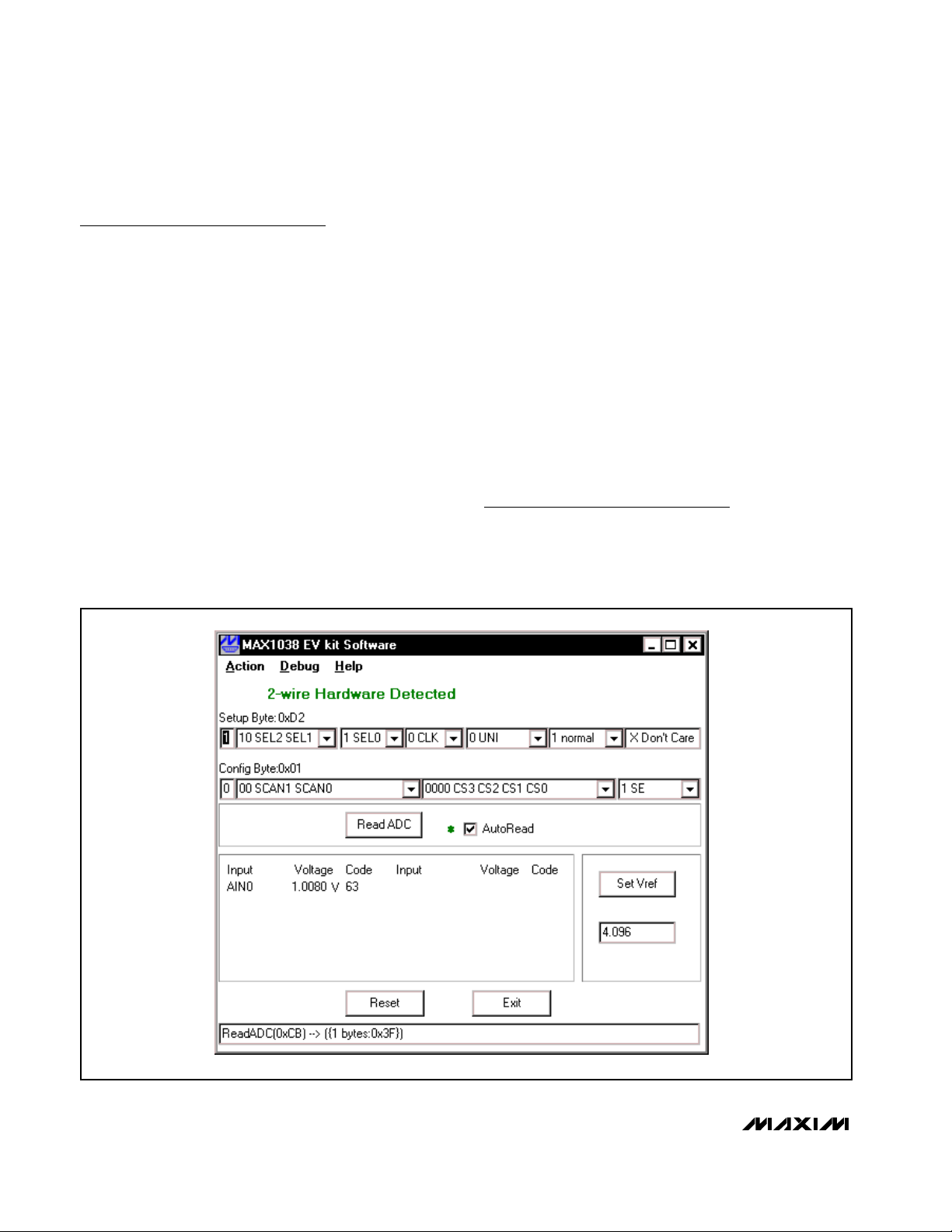
The evaluation software’s main window (Figure 1) controls the setup byte and config byte. It also displays
the voltage and output code of the input signal(s),
depending on the configuration of the MAX1038.
Figure 1. MAX1038 Evaluation Software’s Main Window

Evaluates: MAX1038
MAX1038 Evaluation Kit
_______________________________________________________________________________________ 3
Read ADC
The Read ADC button manually reads the MAX1038
while using the current setup and configuration byte settings. When the AutoRead checkbox is checked, the
software automatically reads the MAX1038 approximately every 300ms. AutoRead allows users to modify
the setup and configuration bytes on-the-fly without having to manually press the Read ADC button each time.
Setup Byte
The Setup Byte always begins with a start bit value of 1.
The SEL2, SEL1, and SEL0 bits control the state of the
reference. The CLK bit selects either internal clock or
external clock mode. The UNI/BIP bit selects either
unipolar or bipolar mode. Setting RST to zero resets the
configuration register. The setup register remains
unchanged. The X Don’t Care bit can be ignored. Refer
to the MAX1038 data sheet for more information on the
SEL2, SEL1, and SEL0 bits within the Setup Byte.
Configuration Byte
The Config Byte always begins with a start bit value of
zero. The SCAN1 and SCAN0 bits select the scanning
mode. The CS3, CS2, CS1, and CS0 bits select one of
the twelve analog input channels. The SE/DIFF bit
selects either single-ended or differential mode. Refer
to the MAX1038 data sheet for more information on the
SCAN1, SCAN0, CS3, CS2, CS1, and CS0 bits within
the Config Byte.
Reference Voltage
The evaluation software assumes a 4.096V reference
voltage, unless otherwise specified. To override the
internal 4.096V reference value, ensure bit SEL2 equals
zero and bit SEL1 equals 1 within the Setup Byte.
Then, apply the new reference voltage at the VREF pad
on the board, type in the new reference voltage, without
the volt unit, and press the Set Vref button. The EV kit
software uses the value typed in the Vref field to translate the digital code to a voltage.
Keyboard Navigation
When you type on the keyboard, the system must know
which control should receive the keystrokes. Press the
TAB key to move the keyboard’s focus from one control
to the next. The focused control is indicated by a dotted
outline. SHIFT+TAB moves the focus to the previously
focused control. Buttons respond to the keyboard’s
SPACE bar. Some controls respond to the keyboard’s
UP and DOWN arrow keys. Activate the program’s
menu bar by pressing the F10 key, then press the letter
of the menu item you want. Most menu items have one
letter underlined, indicating their shortcut key.
Detailed Description
of Hardware
The MAX1038 is a twelve channel (six-differential-channel) 8-bit ADC with a 2-wire serial interface. The opencollector inverter (U2) interfaces the PC parallel port to
the 2-wire serial interface. U2 and the associated circuitry are only required when interfacing to the parallel
port. Power the MAX1038 EV kit from a 5V DC power
supply.
User-Supplied 2-Wire Interface
The MAX1038 EV kit provides a proven PC board layout
and software to evaluate the features of the MAX1038.
The Windows software only supports a 2-wire serial
interface in S-Mode. To evaluate the MAX1038 with a
user-supplied 2-wire serial interface in F-Mode or HSMode, do the following:
1) Disconnect the MAX1038 EV kit from the PC parallel
port.
2) Install 3kΩ resistors at locations R16 and R22. (This
resistor value may require optimization for each
system.)
3) Connect the 2-wire bus to the SDA, SCL, and
GND pads.
4) Refer to the MAX1038 data sheet to ensure all timing
specifications are met.

Evaluates: MAX1038
MAX1038 Evaluation Kit
4 _______________________________________________________________________________________
Figure 2. MAX1038 EV Kit Schematic (Sheet 1 of 2)
SDA
SDA
SCL
SCL
R1
AIN7
AIN6
AIN5
AIN4
AIN3
AIN2
14Ω
1%
R2
14Ω
1%
R3
14Ω
1%
R4
14Ω
1%
R5
14Ω
1%
R6
14Ω
1%
C1
0.22µF
C2
0.22µF
C3
0.22µF
C4
0.22µF
C5
0.22µF
C6
0.22µF
10
SDA
9
SCL
1
AIN7
2
AIN6
3
AIN5
4
AIN4
5
AIN3
6
AIN2
U1
MAX1038
VDD
AIN8
AIN9
AIN10
REF/AIN11
GND
AIN0
AIN1
+5V
12
C13
100pF
R12
14Ω
16
15
14
13
11
8
7
1%
C12
0.22µF
R11
14Ω
1%
C11
0.22µF
R10
14Ω
1%
C10
0.22µF
R9
14Ω
1%
C9
0.22µF
R8
14Ω
1%
C8
0.22µF
R7
14Ω
1%
C7
0.22µF
C14
0.1µF
AIN10
AIN11
AIN8
AIN9
AIN0
AIN1
+5V
GND
GND
V
REF
GND
+5V
GND

Evaluates: MAX1038
MAX1038 Evaluation Kit
_______________________________________________________________________________________ 5
Figure 2. MAX1038 EV Kit Schematic (Sheet 2 of 2)
J1-DB25 CONNECTOR
J1-5
J1-13
J1-18
J1-19
J1-20
J1-21
J1-22
J1-23
J1-24
J1-25
J1-1
J1-4
J1-6
J1-7
J1-8
J1-9
J1-17
J1-16
J1-15
J1-14
J1-10
NC
NC
NC
NC
NC
NC
NC
NC
NC
NC
NC
J1-11
3
1
J1-3
J1-12
3
1
J1-2
+5V
R13
100Ω
D1
R17
100Ω
3
1
R19
100Ω
D3
R23
100Ω
3
1
R14
47kΩ
R18
D2
4.7kΩ
+5V
R20
47kΩ
R24
D4
4.7kΩ
U2-A
21
74HC05
U2-B
34
U2-C
65
74HC05
U2-D
98
+5V
+5V
R15
47kΩ
R21
47kΩ
+5V
+5V
R16
OPEN
R22
OPEN
SDA
SCL
11
74HC05
13
U2-E
U2-F
+5V
10
14
C15
0.1µF
7
12

Maxim cannot assume responsibility for use of any circuitry other than circuitry entirely embodied in a Maxim product. No circuit patent licenses are
implied. Maxim reserves the right to change the circuitry and specifications without notice at any time.
6 _____________________Maxim Integrated Products, 120 San Gabriel Drive, Sunnyvale, CA 94086 408-737-7600
© 2002 Maxim Integrated Products Printed USA is a registered trademark of Maxim Integrated Products.
Evaluates: MAX1038
MAX1038 Evaluation Kit
Figure 3. MAX1038 EV Kit Component Placement Guide—
Component Side
Figure 4. MAX1038 EV Kit PC Board Layout—Component Side
Figure 5. MAX1038 EV Kit PC Board Layout—Solder Side
 Loading...