

Page 1
General Description
The DS4M125/DS4M133/DS4M200 are margining clock
oscillators with LVPECL or LVDS outputs. They are
designed to fit in a 5mm x 3.2mm ceramic package with
an AT-cut fundamental-mode crystal to form a complete
clock oscillator. The circuit can generate the following
frequencies and their ±5% frequency deviations:
125MHz, 133.33MHz, and 200MHz. The DS4M125/
DS4M133/DS4M200 employ a low-jitter PLL to generate
the frequencies. The typical phase jitter is less than
0.9ps RMS from 12kHz to 20MHz.
Frequency margining is a circuit operation to change
the output frequency to 5% higher or 5% lower than the
nominal frequency. Frequency margining is accomplished through the margining select pin, MS. This
three-state input pin accepts a three-level voltage signal
to control the output frequency. In a low-level state, the
output frequency is set to the nominal frequency. When
set to a high-level state, the frequency output is set to
the nominal frequency plus 5%. When set to the midlevel state, the frequency output is equal to the nominal
frequency minus 5%. If left open, the MS pin is pulled
low by an internal 100kΩ (nominal) pulldown resistor.
The DS4M125/DS4M133/DS4M200 are available with
either an LVPECL or LVDS output. The output can be
disabled by pulling the OE pin low. When disabled,
both OUTP and OUTN levels of the LVPECL driver go to
the LVPECL bias voltage, while the output of the LVDS
driver is a logical one. The OE input is an active-high
logic signal and has an internal 100kΩ pullup resistor.
When OE is in a logic-high state, the OUTP and OUTN
outputs are enabled.
The devices operate from a single 3.3V supply voltage.
Applications
Memory Clocks
RAID Systems
Features
♦ Frequency Margining: ±5%
♦ Nominal Clock Output Frequencies: 125MHz,
133.33MHz, and 200MHz
♦ Jitter < 0.9ps RMS from 12kHz to 20MHz
♦ LVPECL or LVDS Output
♦ 3.3V Operating Voltage
♦ Operating Temperature Range: -40°C to +85°C
♦ Supply Current: < 100mA at 3.3V
♦ Excellent Power-Supply Noise Rejection
♦ 5mm x 3.2mm Ceramic LCCC Package
♦ Output Enable/Disable
DS4M125/DS4M133/DS4M200
3.3V Margining Clock Oscillator with
LVPECL/LVDS Output
________________________________________________________________
Maxim Integrated Products
1
Ordering Information
DS4M125/
DS4M133/
DS4M200
DS4M125/
DS4M133/
DS4M200
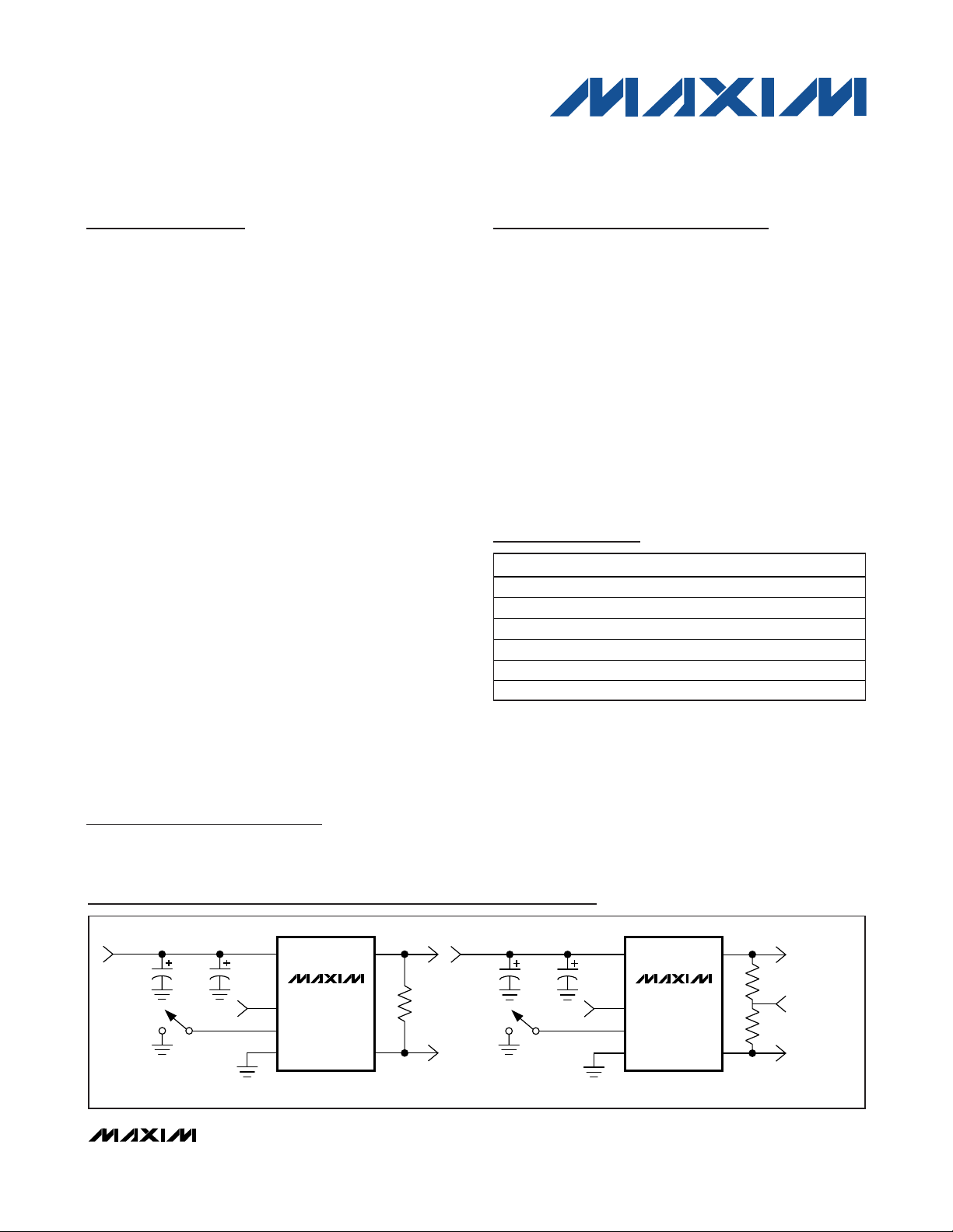
VCC OUTP
OUTN
LVDS OPTION
OE
MS
GND
0.01μF
0.1μF
100Ω
OE
MS
GND
VCC OUTP
OUTN
LVPECL OPTION
0.01μF
0.1μF
50Ω
50Ω
PECL_BIAS AT
V
CC
- 2.0V
Typical Operating Circuit
Rev 0; 12/07
For pricing, delivery, and ordering information, please contact Maxim Direct at 1-888-629-4642,
or visit Maxim’s website at www.maxim-ic.com.
+
Denotes a lead(Pb)-free package. The lead finish is JESD97
category e4 (Au over Ni) and is compatible with both lead-based
and lead-free soldering processes.
Pin Configuration and Selector Guide appear at end of
data sheet.
PART TEMP RANGE PIN-PACKAGE
DS4M125P+33 -40°C to +85° C 10 LCCC
DS4M125D+33 -40°C to +85°C 10 LCCC
DS4M133P+33 -40°C to +85° C 10 LCCC
DS4M133D+33 -40°C to +85°C 10 LCCC
DS4M200P+33 -40°C to +85° C 10 LCCC
DS4M200D+33 -40°C to +85°C 10 LCCC
Page 2
DS4M125/DS4M133/DS4M200
3.3V Margining Clock Oscillator with
LVPECL/LVDS Output
2 _______________________________________________________________________________________
ABSOLUTE MAXIMUM RATINGS
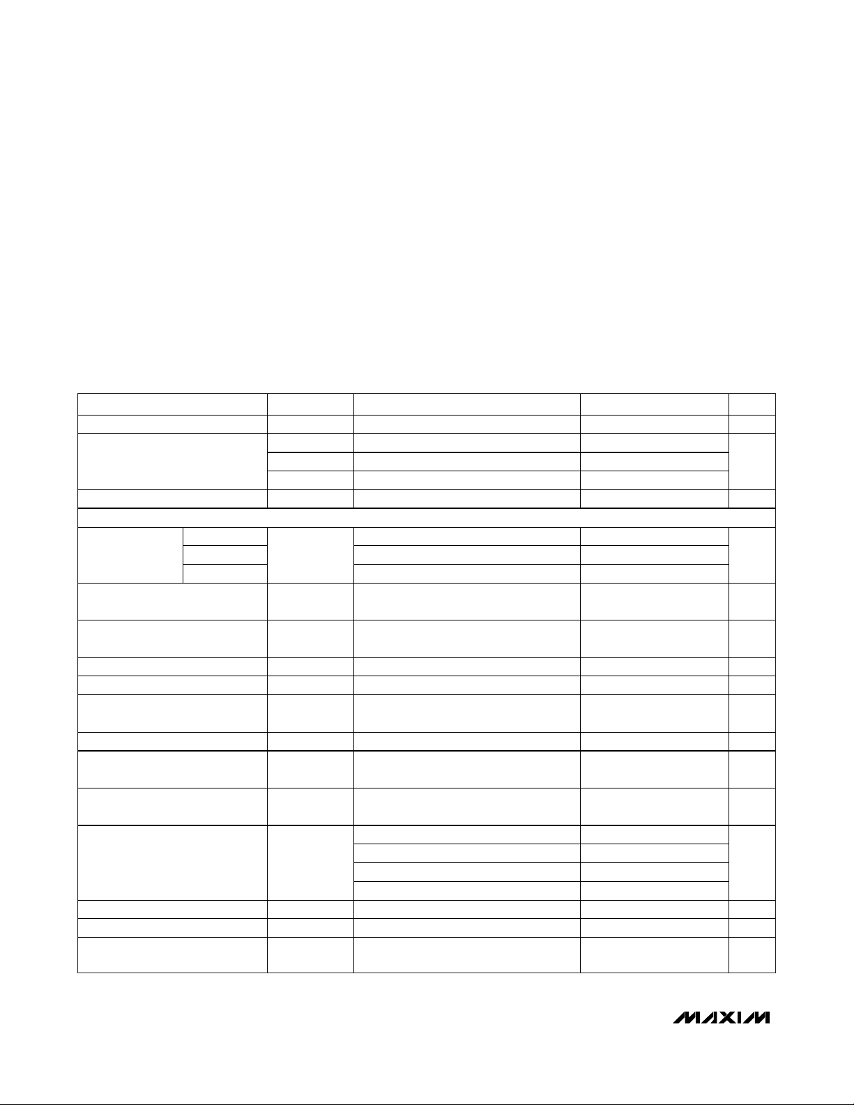
ELECTRICAL CHARACTERISTICS
(VCC= 3.135V to 3.465V, TA= -40°C to +85°C, unless otherwise noted.) (Notes 1, 2)
Stresses beyond those listed under “Absolute Maximum Ratings” may cause permanent damage to the device. These are stress ratings only, and functional
operation of the device at these or any other conditions beyond those indicated in the operational sections of the specifications is not implied. Exposure to
absolute maximum rating conditions for extended periods may affect device reliability.
Power-Supply Voltage Range (VCC) .....................-0.3V to +4.0V
Continuous Power Dissipation (T
A
= +70°C) ...................330mW
Operating Temperature Range ...........................-40°C to +85°C
Junction Temperature......................................................+125°C
Storage Temperature Range ...............................-55°C to +85°C
Soldering Temperature
(3 passes max of reflow)..........................................Refer to the
IPC/JEDEC J-STD-020 Specification.
PARAMETER SYMBOL CONDITIONS MIN TYP MAX UNITS
Operating Voltage Range VCC (Note 1) 3.135 3.3 3.465 V
I
LVDS, output loaded or unloaded 52 75
CC_D
Operating Current
Inactive Current I
OUTPUT FREQUENCY SPECIFICATIONS
DS4M125 MS = 0, OE = 1 125
Frequency
Frequency Stability f
Frequency Stability O ver
Temperature
Initial Tolerance f
Frequency Change Due to V
Frequency Change Due to Load
Variation
Aging (15 Years) f
Phase Jitter J
Accumulated Deterministic Jitter
Due to Reference Spurs
Accumulated Deterministic Jitter
Due to Power-Supply Noise
Startup Time t
Frequency Switch T ime t
Input-Voltage High (OE) VIH (Note 5)
DS4M133 MS = 0, OE = 1 133.33
DS4M200
CC
I
LVPECL, output unloaded 49 70
CC_PU
LVPECL, output loaded 74 100
I
CC_P I
VOE = VIL 52 85 mA
CC_O EZ
f
O
MS = 0, OE = 1 200
TOTAL/fO
f
TEMP
INITIAL/fV
f
VCC
f
LOAD/fO
AGING
RMS
No margin 155.52MHz output 0.6 ps
STRT
SWITCH
Over temperature range, aging, load,
supply, and initial tolerance (Note 3)
/f VCC = 3.3V -35 +35 ppm
VCC = 3.3V, TA = +25°C ±20 ppm
/f VCC = 3.3V ±5% -3 +3 ppm/V
±10% variation in termination
resistance
-7 +7 ppm
Integrated phase RMS; 12kHz to 80MHz,
V
= 3.3V, TA = +25°C
CC
10kHz 12.9
100kHz (Note 4) 26.3
200kHz (Note 4) 20.1
1MHz (Note 4) 6.4
1.0 ms
0.5 ms
-50 +50 ppm
±1 ppm
< 0.9 ps
0.7 x
V
CC
VCC V
mA
MHz
ps
Page 3
DS4M125/DS4M133/DS4M200
3.3V Margining Clock Oscillator with
LVPECL/LVDS Output
_______________________________________________________________________________________ 3
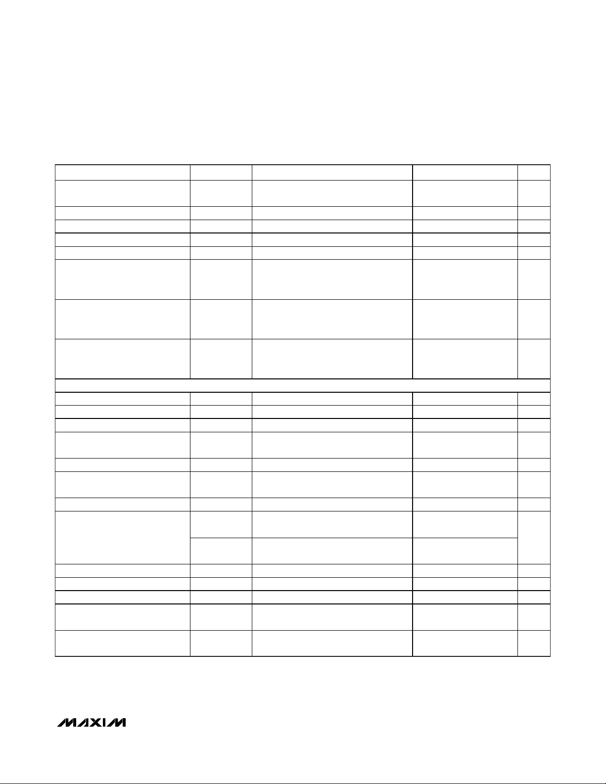
ELECTRICAL CHARACTERISTICS (continued)
(VCC= 3.135V to 3.465V, TA= -40°C to +85°C, unless otherwise noted.) (Notes 1, 2)
PARAMETER SYMBOL CONDITIONS MIN TYP MAX UNITS
Input-Voltage Low (OE) VIL (Note 5) 0
Input-Leakage High (OE) I
Input-Leakage Low (OE) I
Input-Leakage High (MS) I
Input-Leakage Low (MS) I
Input Voltage: High Level (MS) VIH (Note 5)
Input Voltage: Mid Leve l (MS) VIM (Note 5)
Input Voltage: Low Level (MS) VIL (Note 5) 0
LVDS
Output High Voltage VOH 100 differential load (Notes 2, 5) 1.475 V
Output Low Voltage VOL 100 differential load (Notes 2, 5) 0.925 V
Differential Output Voltage
Change in VOD for
Complementary States
Offset Output Voltage VOS 100 differential load (Note 2) 1.125 1.275 V
Change in VOS for
Complementary States
Differential Output Impedance R
L
Output Current
Output Rise Time (Different ia l) t
Output Fall T ime (Differential) t
Duty Cycle D
Propagation Delay from OE Going
LOW to Logical 1 at OUTP
Propagation Delay from OE Going
HIGH to Output Acti ve
CYCLE_LVDS
OE voltage = VCC -5 +5 μA
LEAKH
OE voltage = GND -20 -50 μA
LEAKL
MS vo ltage = VCC 20 50 μA
LEAKH
MS voltage = GND -5 +5 μA
LEAKL
0.75 x
V
+
CC
0.15V
0.25 x
+
V
CC
0.15V
|
|
V
OD
|V
OD
|V
OS
OLVDS
VS SLVDS O
L
LVDSO
RLVDS O
FLVDSO
t
PA1
t
P1A
100 differential load 250 425 mV
|
100 differential load 25 mV
|
100 differential load 150 mV
80 140
OUTN or OUTP shorted to ground and
measure the current in the shorting path
OUTN and OUTP shorted together and
measure the change in I
20% to 80% 175 ps
80% to 20% 175 ps
45 55 %
(Figure 2) 200 ns
(Figure 2) 200 ns
CC
40
6.5
0.3 x
V
CC
VCC V
0.75 x
V
CC
0.15V
0.25 x
V
CC
0.15V
V
-
V
-
V
mA
Page 4

DS4M125/DS4M133/DS4M200
3.3V Margining Clock Oscillator with
LVPECL/LVDS Output
4 _______________________________________________________________________________________
ELECTRICAL CHARACTERISTICS (continued)
(VCC= 3.135V to 3.465V, TA= -40°C to +85°C, unless otherwise noted.) (Notes 1, 2)
Note 1: Limits at -40°C are guaranteed by design and are not production tested. Typical values are at +25°C and 3.3V, unless
otherwise noted.
Note 2: AC parameters are guaranteed by design and characterization and are not production tested.
Note 3: Frequency stability is calculated as: Δf
TOTAL
= Δf
INITIAL
+ Δf
TEMP
+ (Δf
VCC
x 0.165) + Δf
LOAD
+ Δf
AGING
.
Note 4: Supply induced jitter is measured with a 50mV
P-P
sine wave forced on VCC. Deterministic jitter is calculated by measuring
the power of the resulting tone seen on a spectrum analyzer.
Note 5: Voltage referenced to ground.
SINGLE-SIDEBAND PHASE NOISE AT fO= f
NOM
PARAMETER SYMBOL CONDITIONS MIN TYP MAX UNITS
LVPECL
Output High Voltage (Note 2) V
Output Low Voltage (Note 2) V
Differential Voltage V
Rise Time t
Fal l Time t
Duty Cycle D
Propagation Delay from OE Going
LOW to Output Three-Stated
Propagation Delay from OE Going
HIGH to Output Acti ve
OH
OL
DIFF_PECL
R-PECL
F-PECL
CYCLE_PECL
t
PAZ
t
PZA
Output connected to 50 at PECL_BIAS
at V
- 2.0V
CC
Output connected to 50 at PECL_BIAS
- 2.0V
at V
CC
Output connected to 50 at PECL_BIAS
- 2.0V
at V
CC
20% to 80% 200 ps
80% to 20% 200 ps
45 55 %
(Figure 3) 200 ns
(Figure 3) 200 ns
-
V
CC
1.085
V
-
CC
1.825
0.595 0.710 V
V
-
CC
0.88
VCC -
1.62
V
V
fM =
10Hz -70 -75 -70
100Hz -100 -105 -100
1kH z -118 -121 -115
10kHz -118 -122 -117
100kHz -124 -126 -122
1MHz -142 -141 -138
10MHz -150 -150 -150
20MHz -150 -150 -150
SINGLE-SIDEBAND PHASE NOISE AT fO = f
125MHz 133.33MHz 200MHz
NOM
(dBc/Hz)
Page 5

DS4M125/DS4M133/DS4M200
3.3V Margining Clock Oscillator with
LVPECL/LVDS Output
_______________________________________________________________________________________ 5
Pin Description
Typical Operating Characteristics
(VCC= +3.3V, TA = +25°C, unless otherwise noted.)
PIN NAME FUNCTION
1 OE Active-High Output Enable. Has an internal pullup 100k resistor.
2 MS Margin Select. Three-level input with a 100k pul ldown res istor.
3 GND Ground
4 OUTP Posit ive Output for LVPECL or LVDS
5 OUTN Negati ve Output for LVPECL or LVDS
6 VCC Supply Voltage
7–10 N.C. No Connection. Must be floated.
— EP
Exposed Paddle. The exposed pad must be used for thermal relief. This pad must be connected to
ground.
FREQUENCY vs. TEMPERATURE
5
3
0
-3
-5
DEVIATION (ppm)
-8
OUT
f
-10
-13
-15
-40
f
O
TEMPERATURE (°C)
fO + 5%
fO - 5%
DS4M125/DS4M133/DS4M200 toc01
8060-20 0 20 40
(mA)
CC
I
CURRENT vs. TEMPERATURE
59
57
55
53
51
49
47
45
-40
TEMPERATURE (°C)
DS4M125/DS4M133/DS4M200 toc02
8060-20 0 20 40
Page 6

DS4M125/DS4M133/DS4M200
Detailed Description
The DS4M125/DS4M133/DS4M200 consist of an oscillator designed to oscillate with a fundamental-mode
crystal and a PLL to synthesize the base frequency with
its ±5% deviations. The output interface is either
LVPECL or LVDS.
The ±5% frequency deviation is controlled through a
three-level margining select (MS) pin. This three-state
input pin accepts a three-level voltage signal to control
the output frequency. In a low-level state, the output
frequency is set to the nominal frequency. When set to
a high-level state, the frequency output is set to the
nominal frequency plus 5%. When set to the mid-level
state, the frequency output is equal to the nominal frequency minus 5%. The MS pin has an internal 100kΩ
pulldown resistor. When the pin is left floating, the
devices output a nominal frequency.
The devices are available with either LVDS or LVPECL
output drivers. When the OE signal is low, the LVPECL
output driver is turned off and the output voltage goes
to the PECL_BIAS level of VCC- 2.0V, while the LVDS
outputs are a logical one. The OE pin has an internal
100kΩ pullup resistor. When the pin is left floating, the
device output is active.
3.3V Margining Clock Oscillator with
LVPECL/LVDS Output
6 _______________________________________________________________________________________
Figure 1. Functional Diagram
Figure 2. LVDS Output Timing Diagram When OE Is Enabled
and Disabled
Figure 3. LVPECL Output Timing Diagram When OE Is Enabled
and Disabled
X1
DIVFB
LC-VCO
DIVP
DIVOUT
X2
DS4M125/
DS4M133/
DS4M200
THREE-
STATE
PHASE
DET
FILTER
OUTSELN
VCC
OE
OUTP
OUTDRV
OUTN
FREQUENCY SELECTION
MS
THREE-
LEVEL
DECODER
GND
0.7 x V
OUTP
CC
OE
t
P1A
0.3 x V
t
PA1
CC
OE
OUTP
0.7 x V
CC
t
PZA
PECL_BIAS PECL_BIAS
0.3 x V
t
PAZ
CC
OUTN
PECL_BIAS PECL_BIAS
OUTN
Page 7

DS4M125/DS4M133/DS4M200
3.3V Margining Clock Oscillator with
LVPECL/LVDS Output
Maxim cannot assume responsibility for use of any circuitry other than circuitry entirely embodied in a Maxim product. No circuit patent licenses are
implied. Maxim reserves the right to change the circuitry and specifications without notice at any time.
Maxim Integrated Products, 120 San Gabriel Drive, Sunnyvale, CA 94086 408-737-7600 _____________________
7
© 2007 Maxim Integrated Products Maxim is a registered trademark of Maxim Integrated Products, Inc.
Selector Guide
+
Denotes a lead-free package. The lead finish is JESD97 category e4 (Au over Ni) and is compatible with both lead-based
and lead-free soldering processes. A + appears anywhere on
the top mark.
Chip Information
SUBSTRATE CONNECTED TO GROUND
PROCESS: BiPOLAR SiGe
Pin Configuration
Thermal Information
Package Information
For the latest package outline information and land patterns, go
to www.maxim-ic.com/packages
.
PACKAGE TYPE PACKAGE CODE DOCUMENT NO.
10 LCCC L1053+H2
21-0389
PART
DS4M125P+33 125 LVPECL MEP
DS4M125D+33 125 LVDS MED
DS4M133P+33 133.33 LVPECL MFP
DS4M133D+33 133.33 LVDS MFD
DS4M200P+33 200 LVPECL MJP
DS4M200D+33 200 LVDS MJD
FREQUENCY
(NOM) (MHz)
OUTPUT
TYPE
TOP MARK
TOP VIEW
OE
MS
N.C. N.C.
+
1
2
DS4M125/
DS4M133/
DS4M200
6
VCC
5
OUTN
THETA-JA (°C/W)
90
4
3
GND
(5.00mm × 3.20mm × 1.49mm)
*EXPOSED PAD
*EP
N.C. N.C.
OUTP
 Loading...