

Page 1
DS4106/DS4212/DS4425
106.25MHz/212.5MHz/425MHz
Clock Oscillators
Rev 2; 4/08
General Description
The DS4106, DS4212, and DS4425 ceramic surfacemount crystal oscillators are part of Maxim’s DS4-XO
series of crystal oscillators. These devices offer output
frequencies at 106.25MHz, 212.5MHz, and 425MHz.
The clock oscillators are suited for systems with tight tolerances because of the jitter, phase noise, and stability
performance. The small package provides a format
made for applications where PCB space is critical.
These clock oscillators are crystal based and use a fundamental crystal with PLL technology to provide the
final output frequencies. Each device is offered with
LVDS or LVPECL output types. The output enable pin is
active-high logic.
These clock oscillators have very low phase jitter and
phase noise. Typical phase jitter is < 0.9ps RMS from
12kHz to 20MHz. The devices are designed to operate
with a 3.3V ±10% supply voltage, and are available in a
5.0mm x 3.2mm x 1.49mm, 10-pin LCCC surface-mount
ceramic package.
Applications
Fibre Channel Hard Disk Drives
Host Bus Adapters
Raid Controllers
Fibre Channel Switches
Features
♦ Clock Output Frequencies:
DS4106: 106.25MHz
DS4212: 212.50MHz
DS4425: 425.00MHz
♦ Phase Jitter (RMS): 0.9ps Typical
♦ LVPECL or LVDS Output
♦ Supply Current:
50mA (Typical, Unloaded) at +3.3V Supply
(LVPECL)
53mA (Typical) at +3.3V Supply (LVDS)
♦ -40°C to +85°C Temperature Range
♦ Output Disable
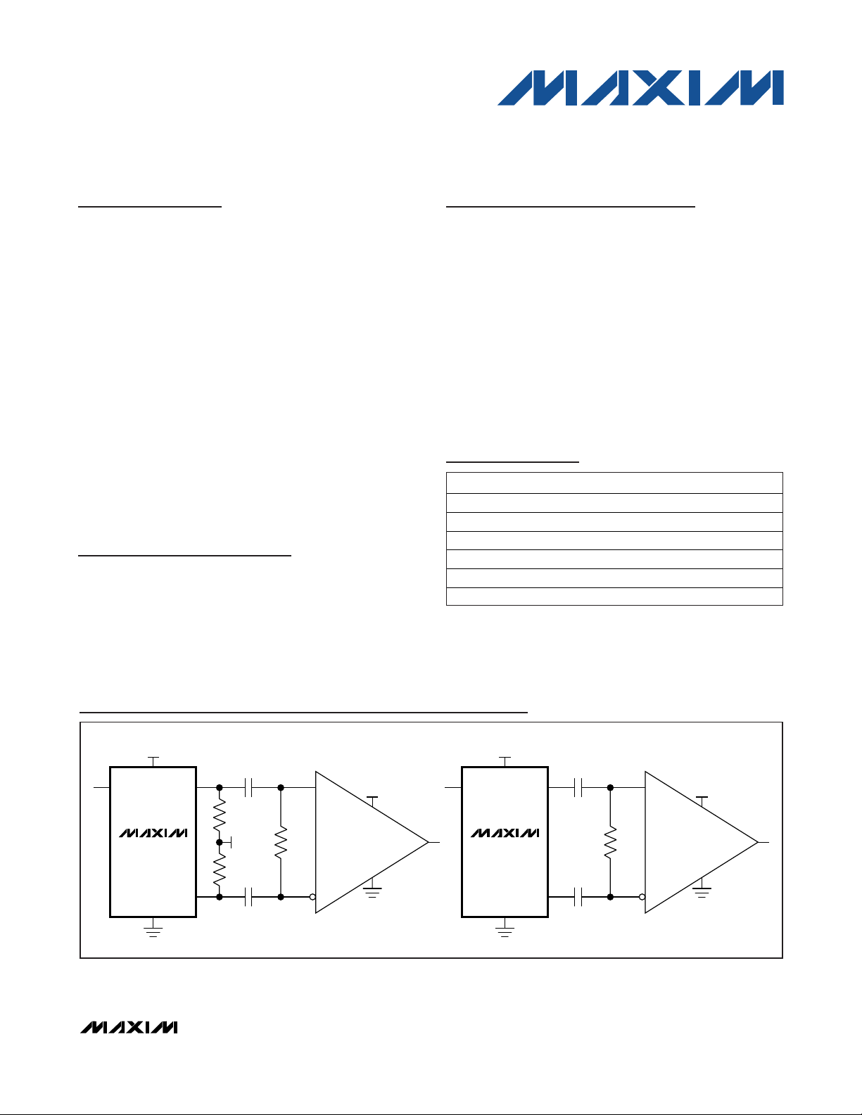
VCC - 2V
100Ω
50Ω
LVPECL OPTION LVDS OPTION
50Ω
V
CC
V
CC
V
CC
GND
OE
OUTP
OUTN
100Ω
V
CC
V
CC
V
CC
GND
OE
OUTP
OUTN
LVPECL LVDS
DS4106/
DS4212/
DS4425
DS4106/
DS4212/
DS4425
Typical Operating Circuits
Pin Configuration and Selector Guide appear at end of
data sheet.
________________________________________________________________
Maxim Integrated Products
1
For pricing, delivery, and ordering information, please contact Maxim Direct at 1-888-629-4642,
or visit Maxim’s website at www.maxim-ic.com.
+
Denotes a lead(Pb)-free package. The lead finish is JESD97
category e4 (Au over Ni) and is compatible with both lead-based
and lead-free soldering processes.
Ordering Information
PART TEMP RANGE PIN-PACKAGE
DS4106AN+ -40°C to +85°C 10 LCCC
DS4106BN+ -40°C to +85°C 10 LCCC
DS4212AN+ -40°C to +85°C 10 LCCC
DS4212BN+ -40°C to +85°C 10 LCCC
DS4425AN+ -40°C to +85°C 10 LCCC
DS4425BN+ -40°C to +85°C 10 LCCC
Page 2
DS4106/DS4212/DS4425
106.25MHz/212.5MHz/425MHz
Clock Oscillators
2 _______________________________________________________________________________________
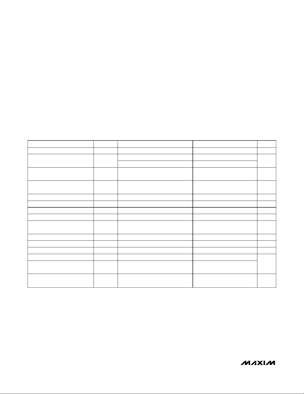
ELECTRICAL CHARACTERISTICS
(VCC= 3.0V to 3.6V, TA= -40°C to +85°C, typical values are at VCC= +3.3V and TA= +25°C, unless otherwise noted.) (Note 1)
Stresses beyond those listed under “Absolute Maximum Ratings” may cause permanent damage to the device. These are stress ratings only, and functional
operation of the device at these or any other conditions beyond those indicated in the operational sections of the specifications is not implied. Exposure to
absolute maximum rating conditions for extended periods may affect device reliability.
VCC, GND, OE, OUTP, OUTN .....................................-0.3V, +4V
Operating Temperature Range ...........................-40°C to +85°C
Junction Temperature......................................................+150°C
Storage Temperature Range .............................-40°C to +125°C
Soldering Temperature Profile
(3 passes max) ...............................See IPC/JEDEC J-STD-020
Specification
ABSOLUTE MAXIMUM RATINGS
PARAMETER SYMBOL CONDITIONS MIN TYP MAX UNITS
Supply Voltage VCC (Note 2) 3.0 3.3 3.6 V
Supply Current I
TTL Control Input-Voltage High
(OE)
TTL Control Input-Voltage Low
(OE)
Input Leakage Current IIL GND OE V
LVPECL OUTPUTS (Note 4)
Output High Voltage VOH (Note 2) VCC - 1.085 VCC - 0.88 V
Output Low Voltage VOL (Note 2) VCC - 1.825 VCC - 1.62 V
Output Leakage Current
(Absolute)
LVDS OUTPUTS (Figure 2)
LVDS Output High Voltage VOH (Note 2) 1.475 V
LVDS Output Low Voltage VOL (Note 2) 0.925 V
LVDS Differential Output Voltage |VOD| 250 400
LVDS Change in VOD for
Complementar y State s
LVDS Offset Output Voltage
(Output Common-Mode Voltage)
|V
CC
V
V
I
OL
V
OS
LVPECL (Note 3) 50 65
LVDS 53 67
(Note 2) 2 VCC V
IH
(Note 2) 0 0.8 V
IL
OE = VIL 100 μA
|
25
OD
(Note 5) 1.125 1.275 V
CC
-50 +10 μA
mA
mV
Page 3
DS4106/DS4212/DS4425
106.25MHz/212.5MHz/425MHz
Clock Oscillators
_______________________________________________________________________________________ 3
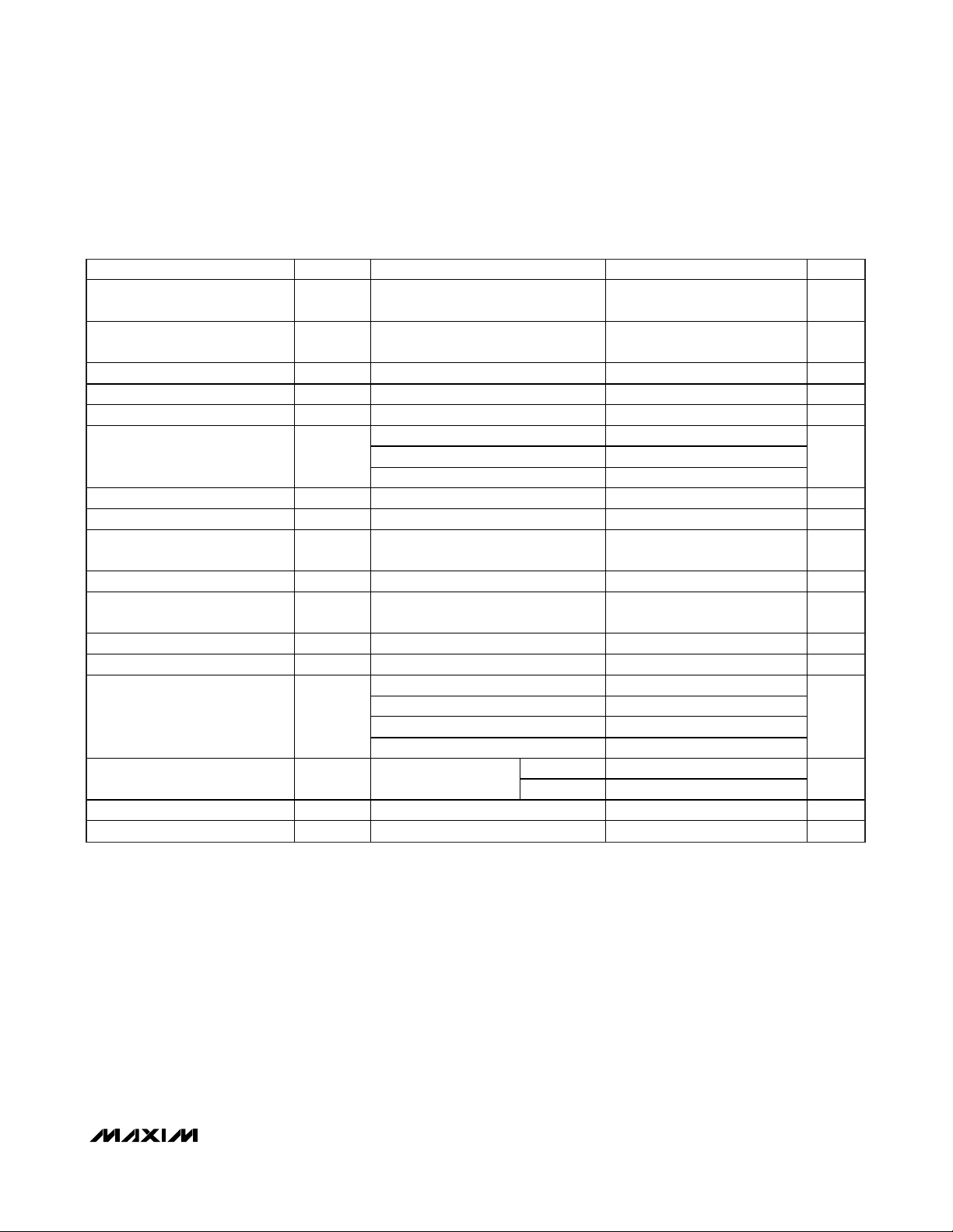
ELECTRICAL CHARACTERISTICS (continued)
(VCC= 3.0V to 3.6V, TA= -40°C to +85°C, typical values are at VCC= +3.3V and TA= +25°C, unless otherwise noted.) (Note 1)
PARAMETER SYMBOL CONDITIONS MIN TYP MAX UNITS
LVDS Change in VOS for
Complementar y State s
LVDS Differential Output
Impedance
LVDS Output Current I
Output Current I
CLOCK OUTPUT
Cloc k Output Frequency f
Frequency Stabilit y Total f / fO Temperature, aging, load, and supply -39 +39 ppm
Init ial Frequenc y Tolerance f
Frequency Stabilit y vs.
Temperature
Frequency Stabilit y vs. V
Frequency Stabilit y vs. Load
Aging (15 Years) f
Phase Jitter (RMS) PJ
Accumulated Deterministic
Jitter Due to Power-Supply Noise
(P-P)
Cloc k Output Edge Speeds tR, tF 20% to 80%
Cloc k Output Duty C yc le +25°C 45 55 %
Oscillation Startup Time (Note 6) 10 ms
CC
|
150 mV
|V
OS
R
VSSLVDSO
f / f
f / fO|V VCC = 3.3V ±10% -3 +3 ppm/V
80 140
OLVDS O
Outputs shorted together 12 mA
LVDSO
Short to ground 40 mA
DS4106 106.25
DS4212 212.5
O
DS4425 425.0
+25°C, ±3°C, VCC = 3.3V ±20 ppm
_TOL
-30 +30 ppm
O|TA
f / f
|
LOAD
AGING
RMS
±10% variation in termination
O
resistance
-7 +7 ppm
12 kHz to 20MHz 0.9 ps
10kHz 3
100kHz 27
200kHz 15
1MHz 7
LVPECL 200
LVDS 175
±1 ppm
MHz
ps
ps
Page 4

DS4106/DS4212/DS4425
106.25MHz/212.5MHz/425MHz
Clock Oscillators
4 _______________________________________________________________________________________
Note 1: Limits at -40°C are guaranteed by design and are not production tested.
Note 2: Voltage referenced to ground.
Note 3: Outputs are enabled and unloaded.
Note 4: When the LVPECL output is disabled, the typical output off current is < 100µA for nominal LVPECL signal levels at the
output.
Note 5: AC parameters are guaranteed by design and characterization.
Note 6: Including oscillator startup time and PLL acquisition time, measured after V
CC
reaches 3.0V from power-on.
ELECTRICAL CHARACTERISTICS (continued)
(VCC= 3.0V to 3.6V, TA= -40°C to +85°C, typical values are at VCC= +3.3V and TA= +25°C, unless otherwise noted.) (Note 1)
PARAMETER SYMBOL CONDITIONS MIN TYP MAX UNITS
100Hz -90
1kH z -112
DS4106 at 106.25MH z
Clock Output SSB Phase Noise
DS4212 at 212.50MH z
DS4425 at 425.00MH z
10kHz -115
100kHz -123
1MHz -142
10MHz -147
100Hz -82
1kH z -106
10kHz -109
100kHz -117
1MHz -136
10MHz -141
100Hz -76
1kH z -100
10kHz -103
100kHz -111
1MHz -130
10MHz -135
dBc/Hz
Page 5

DS4106/DS4212/DS4425
Pin Description
Detailed Description
The DS4106/DS4212/DS4425 combine a crystal and an
IC to form a precision clock. Figure 1 shows a functional diagram of the devices. The IC consists of a crystal
oscillator, a low-noise PLL, selectable clock-divider circuitry, and an output buffer. The PLL consists of a digital phase/frequency detector (PFD) and low-jitter
generation VCO. The VCO signal is scaled by a clockdivider circuit and applied to the output buffer.
Output Drivers
All devices are available with either LVPECL
(DS4106A/DS4212A/DS4425A) or LVDS (DS4106B/
DS4212B/DS4425B) output buffers. When not needed,
the output buffers can be disabled. When disabled, the
LVPECL output buffer goes to a high-impedance state.
However, the LVDS outputs go to a differential logic
one (OUTP latched high and OUTN latched low) when
the outputs are disabled.
Additional Information
For more available frequencies, refer to the DS4125
data sheet at www.maxim-ic.com/DS4125.
Figure 1. Functional Diagram
106.25MHz/212.5MHz/425MHz
Clock Oscillators
_______________________________________________________________________________________ 5
PIN NAME FUNCTION
Output Enable. On-chip pullup resi stor. Connect OE to logic-high, V
1 OE
2, 7–10 N.C. No Connection
3 GND Ground
4 OUTP Positi ve C lock Output, LVPECL or LVDS
5 OUTN Negative Clock Output, LVPECL or LVDS
6 VCC +3.3V Supply
— EP Exposed Paddle. Do not connect this pad or place exposed metal under the pad.
output cloc k. Connect OE to logic-low or GND to disable the output clock. The LVPECL output
clock is set to high impedance when disabled. The LVDS output clock is latched to a differential
high when disabled.
, or leave open to enable the
CC
OSCILLATOR
AMPLIFIER
DS4106/
DS4212/
DS4425
PFD
V
CC
LOOP FILTER VCO COUNTER M
COUNTER N
OUTPUT
BUFFER
OUTP
OUTN
V
CC
OE
GND
Page 6

DS4106/DS4212/DS4425
106.25MHz/212.5MHz/425MHz
Clock Oscillators
6 _______________________________________________________________________________________
+
Denotes a lead-free package. The lead finish is JESD97 category e4 (Au over Ni) and is compatible with both lead-based and lead-
free soldering processes.
Figure 2. LVDS Level Definitions
Selector Guide
D RL = 100Ω DC
V
OH
V
OS
V
OL
+V
OD
VODP - P = VOUTP - VOUTN
-V
OD
SINGLE-ENDED
OUTPUT
DIFFERENTIAL
OUTPUT
OUTP
IVODI
OUTN
0V (DIFF)
PART OUTPUTS FREQUENCY (MHz) TOP MARK
DS4106AN+ LVPECL 10 6.25 06A
DS4106BN+ LVDS 106.25 06B
DS4212AN+ LVPECL 21 2.50 12A
DS4212BN+ LVDS 212.50 12B
DS4425AN+ LVPECL 42 5.00 42A
DS4425BN+ LVDS 425.00 42B
Page 7

DS4106/DS4212/DS4425
106.25MHz/212.5MHz/425MHz
Clock Oscillators
_______________________________________________________________________________________ 7
Thermal Information
1
2
3
6
5
4
TOP VIEW
OE
N.C.
N.C.
*EP
*EXPOSED PAD
N.C.
N.C. N.C.
GND
V
CC
OUTN
OUTP
+
(5.00mm × 3.20mm × 1.49mm)
DS4106/
DS4212/
DS4425
Pin Configuration
PACKAGE TYPE PACKAGE CODE DOCUMENT NO.
10 LCCC L1053+H2
21-0389
Package Information
For the latest package outline information and land patterns, go
to www.maxim-ic.com/packages
.
THETA-JA (°C/W)
90
Page 8

DS4106/DS4212/DS4425
106.25MHz/212.5MHz/425MHz
Clock Oscillators
Maxim cannot assume responsibility for use of any circuitry other than circuitry entirely embodied in a Maxim product. No circuit patent licenses are
implied. Maxim reserves the right to change the circuitry and specifications without notice at any time.
8
_____________________Maxim Integrated Products, 120 San Gabriel Drive, Sunnyvale, CA 94086 408-737-7600
© 2008 Maxim Integrated Products Maxim is a registered trademark of Maxim Integrated Products, Inc.
Revision History
REVISION
NUMBER
0 7/07 Initial release. —
1 10/07
2 4/08
REVISION
DATE
DESCRIPTION
In the General Descr iption section, corrected power-supply tolerance from 5% to
10%.
In the Electrical Character istic s table, added the input voltage ma x value of V
and input voltage min of 0 for VIH and VIL; added GND OE VCC for conditions
on input lea kage (I
Reference Spurs parameter to Accumulated Deterministic Jitter Due to PowerSupply Noise.
In the Electrical Character istics table, changed the cloc k output frequency (fO)
typ from 106.2MHz to 106.25MHz.
In the Pin Description, changed the exposed pad description to indicate that it
should not be connected and to avoid placing exposed metal under the pad
location.
); corrected Accumulated Deterministic Jitter Due to
IL
CC
PAGES
CHANGED
1
2, 3
3
5
 Loading...