

Page 1
V
CC
SCL
SDA
X1
X2
V
BAT
GND
SQW/OUT
V
CC
SCL
SDA
X1
X2
V
BAT
GND
SQW/OUT
PDIP (300 mils)SO (150 mils)
TOP VIEW
DS1307+
0°C to +70°C
5.0
8 PDIP (300 mils)
DS1307
DS1307N+
DS1307Z+
DS1307ZN+
-40°C to +85°C
5.0
8 SO (150 mils)
DS1307N
DS1307Z+T&R
0°C to +70°C
5.0
8 SO (150 mils) Tape and Reel
DS1307
DS1307ZN+T&R
DS130
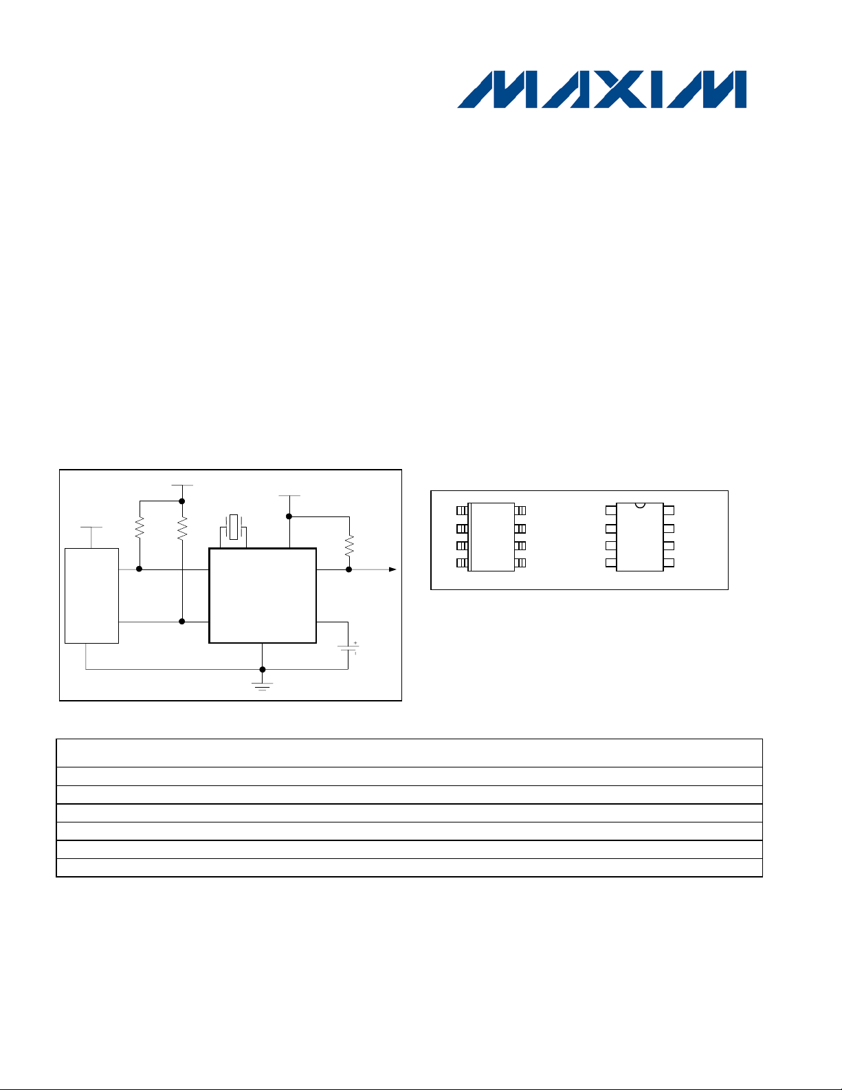
CPU
SDA
SCL
GND
X1
CC
R
R
CRYSTAL
V
R
PU
= t r /C
b
DS1307
Time Clock
64 x 8, Serial, I2C Real-
GENERAL DESCRIPTION
The DS1307 serial real-time clock (RTC) is a lowpower, full binary-coded decimal (B CD) cl oc k/c alendar
plus 56 bytes of NV SRAM. Address and data are
transferred serially through an I
2
C, bidirectional bus.
The clock/calendar provides seconds, mi nutes, hours,
day, date, month, and year information. The end of
the month date is automatically adjusted for months
with fewer than 31 d ays, i ncl uding c orrecti ons f or l eap
year. The cl ock operates in either the 24-hour or 12hour format wit h AM/PM indicator. T he DS1307 has a
built-in power-sense ci rcuit that detects power failur es
and automatically switches to the backup supply.
Timekeeping operation continues while the part
operates from the back up suppl y .
TYPICAL OPERATING CIRCUIT
V
CC
V
FEATURES
Real-Time Clock (RTC) Counts Seconds,
Minutes, Hours, Dat e of t he Month, Month, Day of
the week, and Year with Leap-Year
Compensation Valid Up to 2100
56-Byte, Battery-Backed, General-Purpose RAM
with Unlimited Writes
2
C Serial Interface
I
Programmable S quar e-Wave Output Signal
Automatic Power-Fail Detect and Switch Circuit r y
Consumes Less than 500nA in B att er y-Backup
Mode with Oscillat or Running
Optional Industrial Temperature Range:
-40°C to +85°C
Available in 8-Pin Plastic DIP or SO
Underwriters Laborat or ies (UL) Recognized
PIN CONFIGURATIONS
V
CC
PU
PU
V
X2
CC
SQW/OUT
BAT
ORDERING INFORMATION
PART TEMP RANGE VOLTAGE (V) PIN-PACKAGE TOP MARK*
-40°C to +85°C 5.0 8 PDIP (300 mils) DS1307N
0°C to +70°C 5.0 8 SO (150 mils) DS1307
-40°C to +85°C 5.0 8 SO (150 mils) Tape and Reel DS1307N
+Denotes a lead-free/RoHS-compliant package.
*A “+” anywhere on the top mark ind ic at es a lea d-free package. An “N” anywhere on the top mark indicates an industrial temperature range
device.
1 of 14
REV: 100208
Page 2
DS1307 64 x 8, Serial, I2C Real-Time Clock
Active Supply Curr ent
(f
SCL
= 100kHz)
ABSOLUTE MAXIMUM RATINGS
Voltage Range on Any Pi n Relative to Ground ................................................................................ -0.5V to +7.0V
Operating Temper ature Range (Noncondensing)
Commercial .......................................................................................................................... 0°C to +70°C
Industrial ............................................................................................................................ -40°C to +85°C
Storage Temperature Range ......................................................................................................... -55°C to +125°C
Soldering Temperature (DIP, leads) .................................................................................... +260° C for 10 seconds
Soldering Temperature (surface mount)…..……………………….Refer to the JPC/JEDEC J-STD-020 Specification.
Stresses beyon d those listed u nder “Abs olute M aximu m Rat ings” may cause per manen t dam age to the d evice. T hese ar e stress rating s only ,
and func t ional op erat ion of th e device at t hese or any ot her c o n d it io n s bey ond those indicated in t he op er a t ional sections of the specifica tions is
not implied. Exposure to the absolute maximum rating conditions for extended periods may affect device reliability.
RECOMMENDED DC OPERATING CONDITIONS
(TA = 0°C to +70°C, TA = -40°C to +85°C.) (Notes 1, 2)
PARAMETER SYMBOL CONDITIONS MIN TYP MAX UNITS
Supply Voltage VCC
Logic 1 Input VIH
Logic 0 Input VIL
V
Battery Voltage V
BAT
BAT
4.5 5.0 5.5 V
2.2 VCC + 0.3 V
-0.3 +0.8 V
2.0 3 3.5 V
DC ELECTRICAL CHARACTERISTICS
(VCC = 4.5V t o 5.5V; TA = 0°C to +70°C, T
PARAMETER SYMBOL CONDITIONS MIN TYP MAX UNITS
Input Leakage (SCL) ILI -1 1
I/O Leakage (SDA, SQW/O UT) ILO -1 1
Logic 0 Output (IOL = 5mA) VOL 0.4 V
Standby Current I
V
Leakage Current I
BAT
Power-Fail Voltage (V
= 3.0V) VPF
BAT
= -40°C to +85°C.) (Notes 1, 2)
A
I
1.5 mA
CCA
(Note 3) 200
CCS
5 50 nA
BATLKG
1.216 x
V
BAT
1.25 x
V
BAT
1.284 x
V
BAT
µA
µA
µA
V
DC ELECTRICAL CHARACTERISTICS
(VCC = 0V, V
PARAMETER SYMBOL CONDITIONS MIN TYP MAX UNITS
V
Current (OS C ON);
BAT
SQW/OUT OFF
V
Current (OS C ON);
BAT
SQW/OUT ON (32kHz)
V
Data-Retention Current
BAT
(Oscillator Off)
WARNING: Negative undershoots below -0.3V while the part is in battery-backed mode may cause loss of data.
= 3.0V; TA = 0°C to +70°C, T
BAT
= -40°C to +85°C.) (Notes 1, 2)
A
300 500 nA
I
BAT1
480 800 nA
I
BAT2
10 100 nA
I
BATDR
2 of 14
Page 3

AC ELECTRICAL CHARACTERISTICS
Bus Free Time Between a STOP and
START Condition
Hold Time (Repeated) START
Condition
Setup Time for a Repeated STA RT
Condition
Fall Time of Both SDA and SCL
Signals
Capacitance Load for Each Bus
Line
Not e 3:
(VCC = 4.5V t o 5.5V; TA = 0°C to +70°C, T
PARAMETER SYMBOL CONDITIONS MIN TYP MAX UNITS
= -40°C to +85°C.)
A
DS1307 64 x 8, Serial, I2C Real-Time Clock
SCL Clock Frequency f
t
LOW Period of SCL Clock t
HIGH Period of SCL Clock t
t
Data Hold Time t
Data Setup Time t
Rise Time of Both SDA and SCL
Signals
Setup Time for STOP Condition t
CAPACITANCE
(T
= +25°C)
A
0 100 kHz
SCL
t
4.7
BUF
(Note 4) 4.0
HD:STA
4.7
LOW
4.0
HIGH
4.7
SU:STA
0
HD:DAT
(Notes 5, 6) 250 ns
SU:DAT
1000 ns
t
R
tF 300 ns
4.7
SU:STO
µs
µs
µs
µs
µs
µs
µs
PARAMETER SYMBOL CONDITIONS MIN TYP MAX UNITS
Pin Capacitance ( S DA, SCL) C
10 pF
I/O
CB (Note 7) 400 pF
Not e 1: All volt ages are referenced to ground.
Not e 2: Limits at -40°C are guaranteed by design and are not production tested.
I
specified wi th VCC = 5.0V and SDA, SCL = 5.0V.
CCS
Not e 4: After this period, the first clock puls e is genera ted.
Not e 5: A device must internally provide a hold time of at least 300ns for the SDA signal (referred to the V
signal) to bridge the undefined region of the falling edge of SCL.
Not e 6: The maximum t
Not e 7: C
—total capacitance of one bus line in pF.
B
only has to be met if the device does not stretch the LOW period (t
HD:DAT
) of the SCL signal.
LOW
IH(MIN)
of the S C L
3 of 14
Page 4

TIMING DIAGRAM
RAM
(56 X 8)
SERIAL BUS
INTERFACE
AND ADDRESS
REGISTER
CONTROL
LOGIC
1Hz
1Hz/4.096kHz/8.192kHz/32.768kHz
MUX/
BUFFER
USER BUFFER
(7 BYTES)
CLOCK,
CALENDAR,
AND CONTROL
REGISTERS
POWER
CONTROL
DS1307
X1
C
L
C
L
X2
SDA
SCL
SQW/OUT
V
CC
GND
V
BAT
Oscillator
and divider
N
t
SU:S TO
HD:STA t SU:STA
t
t F t
t
R
SDA
t
BUF
SCL
START
STOP
Figure 1. Block Diagram
t
HD:STA
LOW
t
HD:DAT
HIG H
SU:DAT
DS1307 64 x 8, Serial, I2C Real-Time Clock
t
REPEATED
START
4 of 14
Page 5

TYPICAL OPERATING CHARACTERISTICS
I
CCS
vs. V
CC
0
10
20
30
40
50
60
70
80
90
100
110
120
1.0 2.0 3.0 4.0 5.0
V
CC
(V)
SUPPLY CURRENT (uA
V
BAT
=3.0V
I
BAT
vs. Temperat ur e
175.0
225.0
275.0
325.0
-40 -20 0 20 40 60 80
TEMPERATURE (°C)
SUPPLY CURRENT (nA
V
CC
=0V, V
BAT
=3.0
SQW=32kHz
SQW of f
I
BAT
vs. V
BAT
100
150
200
250
300
350
400
2.0 2.5 3.0 3.5
V
BACKUP
(V)
SUPPLY CURRENT (nA
SQW=32kHz
SQW of f
V
CC
= 0V
SQW/OUT vs. Supply Voltage
32768
32768.1
32768.2
32768.3
32768.4
32768.5
2.0 2.5 3.0 3.5 4.0 4.5 5.0 5.5
Supply (V)
FREQUENCY (Hz)
(VCC = 5.0V, TA = +25°C, unless otherwise noted.)
DS1307 64 x 8, Serial, I2C Real-Time Clock
5 of 14
Page 6

PIN DESCRIPTION
Serial Data Input/O utput. SDA is the data input/out put for t he I2C serial interface. The
up to 5.5V regardless of the voltage on VCC.
Serial Clock Input. SCL is the clock input for the I2C interface and is used to synchroniz e
the voltage on VCC.
Square Wave/Output Driver. When enabled, the SQWE bit set to 1, the SQW/OUT pin
CC
PIN NAME FUNCTION
Connections f or St andar d 32.768kHz Quartz Crystal. The i nternal oscillator cir c uitry is
1 X1
2 X2
3 V
BAT
4 GND Ground
designed for operation with a crystal having a specified load capacitance (C
X1 is the input to the oscill ator and can optionally be connected t o an ex ternal 32.768kHz
oscillator. The output of the internal oscillator, X2, is floated if an external oscillator is
connected to X1.
Note: For more inf ormati on on c r y stal sel ec tion and crystal layout consi der ations, refer to
Application Note 58: Cr y s tal Considerations with Dallas Real-Time Clocks.
Backup Supply Input for A ny St andar d 3V Lithium Cell or Other Energy Sourc e. Batt er y
voltage must be held bet ween the minimum and maximum limits for proper oper ation.
Diodes in series between the batt er y and the V
backup supply is not required, V
) voltage at which acc ess to the RTC and user RAM is denied is set by the internal
(V
PF
circuitry as 1.25 x V
nominal. A lithium batt ery wit h 48m A h or greater will back up the
BAT
must be grounded. The nominal power-fail trip point
BAT
DS1307 for more than 10 years in the absence of power at +25°C.
UL recognized to ensure against reverse charging cur rent when used with a lithium
battery. Go to :
www.maxim-ic.com/qa/info/ul/.
DS1307 64 x 8, Serial, I2C Real-Time Clock
) of 12.5pF.
L
pin may prevent proper operati on. If a
BAT
5 SDA
6 SCL
SDA pin is open drain and requir es an ext er nal pullup resistor. The pull up voltage can be
data movement on the serial interface. The pullup voltage can be up to 5. 5V regardless of
outputs one of four square-wave frequencies (1Hz, 4kHz, 8k Hz, 32k Hz ) . T he SQW/OUT
7 SQW/OUT
pin is open drain and requi r es an ext er nal pullup resistor. SQW/OUT operat es with either
or V
V
CC
. If not used, this pin can be left floating.
V
applied. The pull up voltage can be up to 5.5V regardless of the voltage on
BAT
Primary Power Supply . W hen v oltage is applied within normal limit s, the device is fully
8 VCC
accessible and dat a c an be written and read. When a backup supply is connect ed to the
device and V
is below VTP, read and writes are inhibited. However, t he timek eeping
CC
function continues unaffected by the lower input voltage.
DETAILED DESCRIPTION
The DS1307 is a low-power clock/ calendar with 56 bytes of battery-backed S RAM. The clock/calendar provides
seconds, mi nutes, hours, day, date, month, and year information. T he date at the end of the month is automatically
adjusted for m onths with f ewer than 31 day s, i ncl uding correc ti ons f or l eap year. The DS1307 oper ate s as a slav e
device on the I
code foll owed by a regi ster addre ss. Sub sequent regi st ers can be acc es sed sequent iall y unt il a STOP condi tion i s
executed. When V
address counter. Inputs to the device will not be recognized at this time to prev ent erroneous data from being
written t o the device from an out-of-toler ance system . W hen V
current batt ery-backup mode. Upon power-up, the de vice switches from battery to V
+ 0.2V and recogni zes inputs when VCC i s greater than 1.25 x V
V
BAT
main elements of the serial RTC.
2
C bus. Access is obtained by implementing a START condition and prov iding a device identifi cation
falls below 1.25 x V
CC
, the device terminat es an access in progress and resets the d evice
BAT
f alls below V
CC
. The block di agram in Figure 1 shows the
BAT
, the devic e switches into a low-
BAT
when VCC is greater than
CC
6 of 14
 Loading...