

Page 1
19-0482; Rev 3; 2/10
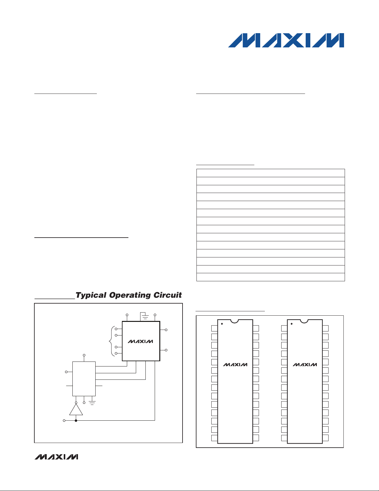
Typical Operating Circuit
Monolithic CMOS Analog Multiplexers
General Description
Maxim’s DG506A/DG507A are monolithic CMOS analog
multiplexers. The DG506A is a single 16-channel (1 of
16) multiplexer and the DG507A is a differential 8-channel (2 of 16) multiplexer.
Both devices feature break-before-make switching.
Maxim guarantees that these multiplexers will not latchup if the power supplies are turned off with the input
signals still present as long as absolute maximum ratings
are not violated. The multiplexers operate over a wide
range of power supplies from Q4.5V to Q18V.
Compared to the original manufacturer’s devices,
Maxim’s DG506A/DG507A consume significantly less
power, making them ideal for portable equipment.
Maxim’s DG506A/DG507A meet or exceed the specifications of, and are drop-in replacements for Intersil’s
IH6116 and IH6216, Siliconix’s DG506A and DG507A,
and Harris’ HI506 and HI507.
Applications
Control Systems
Data Logging Systems
Aircraft Heads Up Displays
Data Acquisition Systems
Signal Routing
-15V -15V
Features
S Improved 2nd Source
S Pin Compatible with Harris, Siliconix, Intersil
S Operable with ±4.5V to ±18V Supplies
S Symmetrical, Bidirectional Operation
S Logic and Enable Inputs, TTL and CMOS Compatible
S Latch-Up Proof Construction
S Monolithic, Low-Power CMOS Design
Ordering Information
†
PART
TEMP RANGE PIN-PACKAGE
DG506AAK -55°C to +125°C 28 CERDIP
DG506ABK -25°C to +85°C 28 CERDIP
DG506AC/D 0°C to +70°C Dice
DG506ACJ 0°C to +70°C 28 Plastic Dip
DG506ACK 0°C to +70°C 28 CERDIP
DG506ACWI 0°C to +70°C 28 Wide SO
DG506AMWI/PR -55°C to +125°C 28 Wide SO
DG507AAK -55°C to +125°C 28 CERDIP
DG507ABK -25°C to +85°C 28 CERDIP
DG507AC/D 0°C to +70°C Dice
DG507ACJ 0°C to +70°C 28 Plastic DIP
DG507ACK 0°C to +70°C 28 CERDIP
DG507ACWI 0°C to +70°C 28 Wide SO
†Devices are available in a lead(Pb)-free/RoHS-compliant
package, specify lead-free by adding “+” to the part number
when ordering.
Pin Configurations
DG506A/DG507A
+
GND
V
S
1a
S
8a
S
1b
S
8b
A
0A1A2
DG507A
CLOCK IN
ENABLE IN
(MUX ON-OFF
CONTROL)
ANALOG
INPUT
(OUTPUTS)
+15V
+
V
Q
B
Q
B
A
NC
8-CHANNEL SEQUENTIAL DIFFERENTIAL MUX/DEMUX
C
H1
Q
D
Q
NC
A
H1
r
GND
02r01
+15V
_______________________________________________________________ Maxim Integrated Products 1
For pricing, delivery, and ordering information, please contact Maxim Direct at 1-888-629-4642,
or visit Maxim’s website at www.maxim-ic.com.
EN
-
V
D
a
D
b
ANALOG
OUTPUT
(INPUTS)
S
S
S
S
S
S
S
GND
+
V
1
NC
2
NC
3
4
16
5
15
DG506A DG507A
6
14
7
13
8
12
9
11
10
10
S
11
9
12
NC
13
A3
14
28
27
26
25
24
23
22
21
20
19
18
17
16
15
+
V
S
S
S
S
S
S
S
S
GND
1
D
2
b
NC
3
4
8b
5
7b
6
6b
7
5b
8
4b
9
3b
10
2b
11
1b
12
NC
13
NC
14
D
-
V
S
8
S
7
S
6
S
5
S
4
S
3
S
2
S
1
EN
A
0
A
1
A
2
28
D
a
-
27
V
26
S
8a
25
S
7a
S
24
6a
S
23
5a
S
22
4a
S
21
3a
S
20
2a
S
19
1a
EN
18
A
17
0
A
16
1
A
15
2
Page 2
Monolithic CMOS Analog Multiplexers
DS(ON)MAX DS(ON)MIN
DS(ON)
DS(ON)AVE
R R
R
R
−
∆ =
ABSOLUTE MAXIMUM RATINGS
(Voltages referenced to V-.)
V+ ..........................................................................................44V
GND .......................................................................................25V
Digital Inputs VS, VD (Note 1) .......................-2V to (V+ + 2V) or
20mA, whichever occurs first
Current, Any Terminal Except S or D .................................30mA
Continuous Current, S or D ................................................20mA
Peak Current, S or D (pulsed at 1ms, 10% duty cycle max) ...40mA
*All leads soldered or welded to PCB.
Stresses beyond those listed under “Absolute Maximum Ratings” may cause permanent damage to the device. These are stress ratings only, and functional
operation of the device at these or any other conditions beyond those indicated in the operational sections of the specifications is not implied. Exposure to absolute
maximum rating conditions for extended periods may affect device reliability.
Continuous Power Dissipation (TA = +70°C)*
28-Pin Ceramic DIP (derate 16.7mW/NC above +70NC) ..1333mW
28-Pin Plastic DIP (derate 14.3mW/NC above +70NC) ...1143mW
28-Pin Wide SO (derate 12.5mW/°C above +70°C) ..1000mW
Operating Temperature Range (A Suffix) ........ -55NC to +125NC
(B Suffix) ..........-25NC to +85NC
(C Suffix) ................ 0NC to +70N
Storage Temperature (A and B Suffix) ............. -65NC to +150NC
(C Suffix) ....................... -65NC to +125NC
Lead Temperature (soldering, 10s) ................................+300NC
DG506A/DG507A
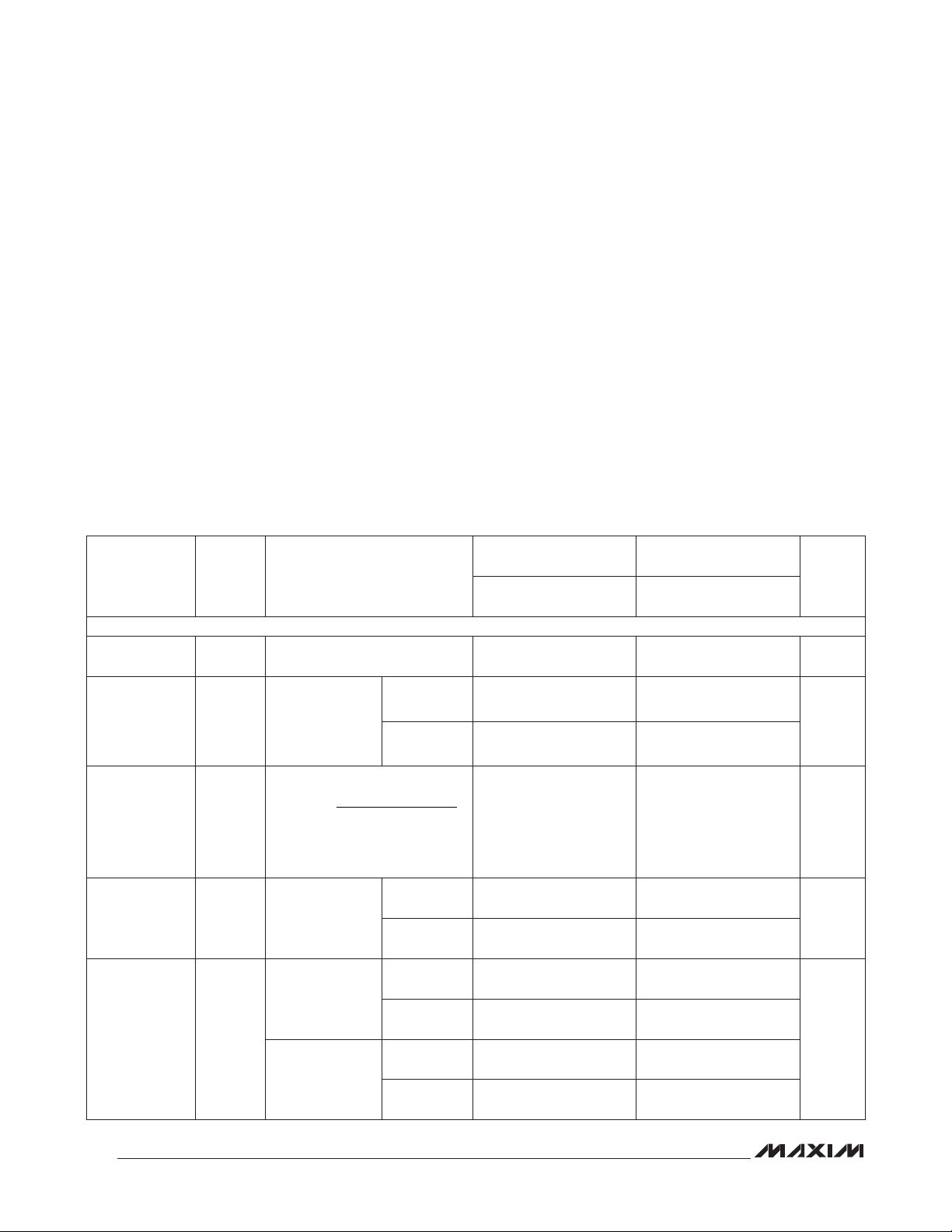
ELECTRICAL CHARACTERISTICS
(V+ = 15V, V- = -15V, V
= 0V, TA = +25NC, unless otherwise indicated.)
GND
PARAMETER SYMBOL CONDITIONS
SWITCH
Analog Signal
Range
V
ANALOG
Sequence each
Drain-toSource
On-Resistance
R
DS(ON)
switch on,
VAL = 0.8V,
VAH = 2.4V,
VEN = 2.4V
Greatest
Change in
Drain-Source
On-Resistance
R
DS(ON)
-10V P VS P +10V
Between
Channels
Source OffLeakage
Current
I
S(OFF)
VEN = 0.8V,
VAL = 0.8V
DG506A,
VEN = 0.8V,
Drain OffLeakage
Current
I
D(OFF)
VAL = 0.8V
DG507A,
VEN = 0.8V,
VAL = 0.8V
VD = 10V,
IS = -200FA
VD = -10V,
IS = -200FA
VS = 10V,
VD = -10V
VS = -10V,
VD = 10V
VD = 10V,
VS = -10V
VD = -10V,
VS = 10V
VD = 10V,
VS = -10V
VD = -10V,
VS = 10V
MIN
(Note 2)
DG506AA
DG507AA
TYP
(Note 3)
MAX
MIN
(Note 2)
DG506AB/C
DG507AB/C
TYP
(Note 3)
MAX
-15 +15 -15 +15 V
270 400 270 450
230 400 230 450
6 6 %
-1 0.002 +1 -5 0.002 +5
-1 -0.005 +1 -5 -0.005 +5
-10 0.02 +10 -20 0.02 +20
-10 -0.03 +10 -20 -0.03 +20
-5 0.007 +5 -10 0.007 +10
-5 -0.015 +5 -10 -0.015 +10
UNITS
I
nA
nA
2
Page 3
Monolithic CMOS Analog Multiplexers
ELECTRICAL CHARACTERISTICS (continued)
(V+ = 15V, V- = -15V, V
PARAMETER SYMBOL CONDITIONS
Channel
On-Leakage
Current
INPUT
Address Input
Current, InputVoltage High
Address Input
Current, InputVoltage Low
DYNAMIC
Switching Time
of Multiplexer
Break-BeforeMake Interval
Enable TurnOn Time
Enable TurnOff Time
Off-Isolation
(Note 5)
Source OffCapacitance
Drain OffCapacitance
SUPPLY
Positive Supply
Current
Negative
Supply Current
t
= 0V, TA = +25NC, unless otherwise indicated.)
GND
I
D(ON)
(Note 4)
I
AH
I
AL
transition
t
OPEN
t
ON(EN)
t
OFF(EN)
OIRR
C
S(OFF)VEN
C
D(OFF)
+
I
-
I
DG506A,
sequence each
switch on,
VAL = 0.8V,
VAH = 2.4V,
VEN = 2.4V
DG507A,
sequence each
switch on,
VAL = 0.8V,
VAH = 2.4V,
VEN = 2.4V
VA = 2.4V -10 -0.002 -10 -0.002
VA = 15V 0.006 10 0.006 10
All VA = 0V
Figure 1 0.6 1 0.06
Figure 3 0.2 0.2
Figure 2 1 1
Figure 2 0.4 0.4
VEN = 0V, RL = 1kI, CL =
15pF, VS = 7V
= 0V, f = 140kHz, VS = 0V 6 6 pF
VEN = 0V,
f = 140kHz
VEN = 0 or 5V, all VA = 0V 0.13 0.25 0.13 0.3
VEN = 0 or 5V, all VA = 0V -0.15 -0.07 -0.25 -0.07
V
= VD
S(all)
= 10V
V
= VD
S(all)
= -10V
V
= VD
S(all)
= 10V
V
= VD
S(all)
= -10V
VEN = 2.4V -10 -0.002 -10 -0.002
VEN = 0V -10 -0.002 -10 -0.002
, f = 500kHz
RMS
DG506A, VD = 0V 45 45
DG507A, VD = 0V 23 23
(Note 2)
DG506AA
DG507AA
MIN
-10 0.03 +10 -20 0.03 +20
-10 -0.06 +10 -20 -0.06 +20
-5 0.015 +5 -10 0.015 +10
-5 -0.03 +5 -10 -0.03 +10
TYP
(Note 3)
MAX
68 68 dB
MIN
(Note 2)
DG506AB/C
DG507AB/C
TYP
(Note 3)
MAX
DG506A/DG507A
UNITS
nA
FA
FA
Fs
Fs
Fs
Fs
pF
mA
3
Page 4

Monolithic CMOS Analog Multiplexers
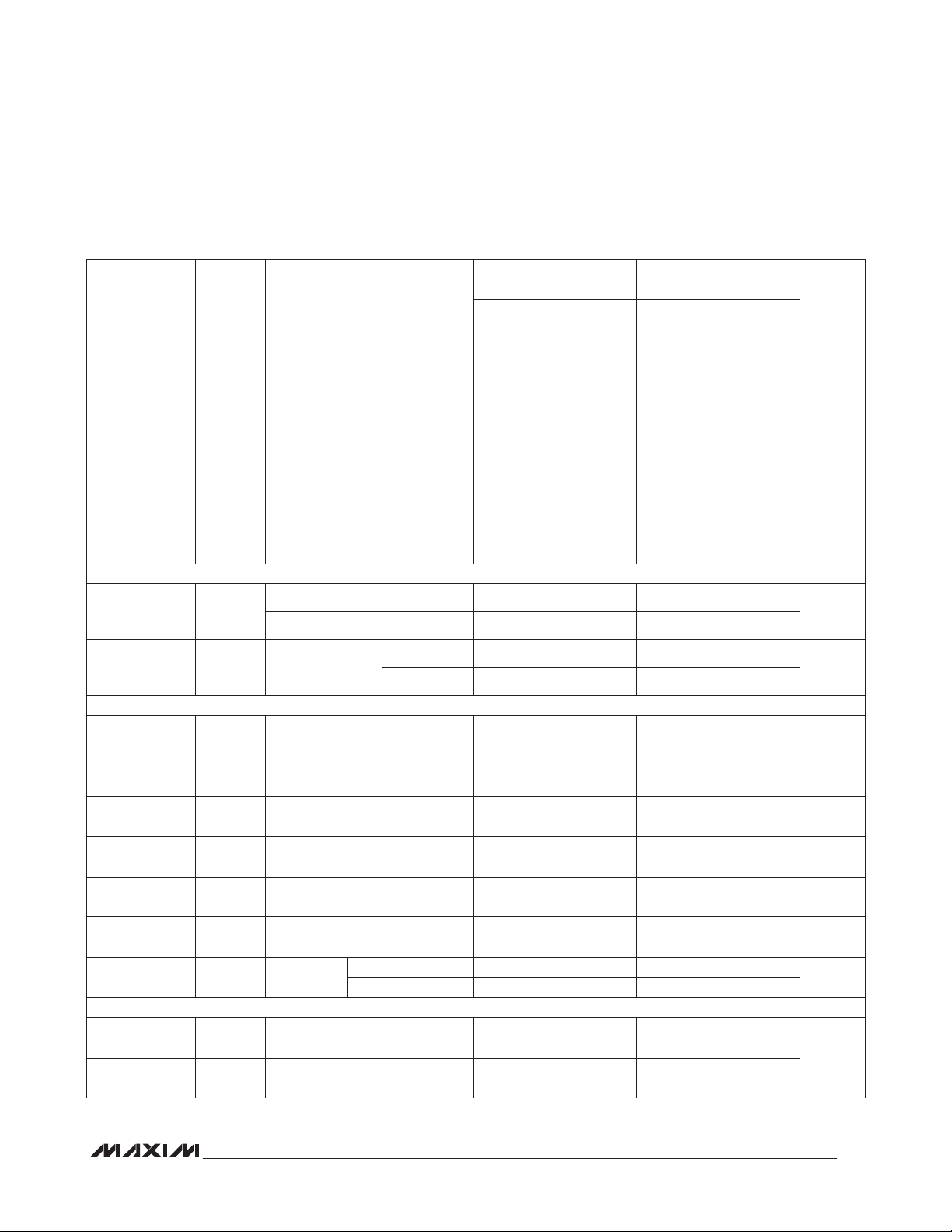
ELECTRICAL CHARACTERISTICS (Overtemperature)
(V+ = 15V, V- = -15V, V
= 0V, TA = overtemperature range, unless otherwise noted.)
GND
PARAMETER SYMBOL CONDITIONS
SWITCH
Analog Signal
Range
Drain-to-Source
On-Resistance
DG506A/DG507A
Source OffLeakage
Current
Drain OffLeakage
Current
Channel
On-Leakage
Current
INPUT
Address Input
Current, InputVoltage High
Address Input
Current, InputVoltage Low
V
ANALOG
R
DS(ON)
I
S(OFF)
I
D(OFF)
I
D(ON)
(Note 4)
I
AH
I
AL
Sequence each
switch on,
VAL = 0.8V,
VAH = 2.4V,
VEN = 2.4V
VEN = 0.8V,
VAL = 0.8V
DG506A,
VEN = 0.8V,
VAL = 0.8V
DG507A,
VEN = 0.8V,
VAL = 0.8V
DG506A,
sequence each
switch on,
VAL = 0.8V,
VAN = 2.4V,
VEN = 2.4V
DG507A,
sequence each
switch on,
VAL = 0.8V,
VAN = 2.4V,
VEN = 2.4V
VA = 2.4V -30 -30
VA = 15V 30 30
All VA = 0V
DG506AA
DG507AA
MIN
(Note 2)
-15 +15 -15 +15 V
VD = 10V, IS
= -200FA
VD = -10V,
IS = -200FA
VS = 10V,
VD = -10V
VS = -10V,
VD = 10V
VD = 10V,
VS = -10V
VD = -10V,
VS = 10V
VD = 10V,
VS = -10V
VD = -10V,
VS = 10V
V
= VD
S(all)
= 10V
V
= VD
S(all)
= -10V
V
= VD
S(all)
= 10V
V
= VD
S(all)
= -10V
VEN = 2.4V -30 -30
VEN = 0V 30 30
-50 +50 -50 +50
-50 +50 -50 +50
-300 +300 -300 +300
-300 +300 -300 +300
-200 +200 -200 +200
-200 +200 -200 +200
-300 +300 -300 +300
-300 +300 -300 +300
-200 +200 -200 +200
-200 +200 -200 +200
TYP
(Note 3)
MAX
500 550
500 550
MIN
(Note 2)
DG506AB/C
DG507AB/C
TYP
(Note 3)
MAX
UNITS
I
nA
nA
nA
FA
FA
4
Page 5

Monolithic CMOS Analog Multiplexers
ELECTRICAL CHARACTERISTICS (Overtemperature) (continued)
(V+ = 15V, V- = -15V, V
Note 1: Signals on SX, DX, or INX exceeding V+ or V- will be clamped by internal diodes. Limit forward diode current to maximum
current ratings.
Note 2: The algebraic convention whereby the most negative value is a minimum, and the most positive value is a maximum, is
used in this data sheet.
Note 3: Typical values are for design aid only, not guaranteed nor subject to production testing.
Note 4: I
is leakage from driver into on switch.
D(ON)
Note 5: Off-isolation = 20log x VO/VS, VS = input to off switch, VD = output due to VS.
Truth Tables
= 0V, TA = over temperature range, unless otherwise noted.)
GND
DG506A/DG507A
A3 A2 A1 A0 EN ON SWITCH
X X X X 0 None
0 0 0 0 1 1
0 0 0 1 1 2
0 0 1 0 1 3
0 0 1 1 1 4
0 1 0 0 1 5
0 1 0 1 1 6
0 1 1 0 1 7
0 1 1 1 1 8
1 0 0 0 1 9
1 0 0 1 1 10
A2 A1 A0 EN ON SWITCH
X X X 0 None
0 0 0 1 1
0 0 1 1 2
0 1 0 1 3
0 1 1 1 4
1 0 0 1 5
1 0 1 1 6
1 1 0 1 7
1 1 1 1 8
Note: Logic “0” = VAL ≤ 0.8V, Logic “1” = VAH ≥ 2.4V,
“0” = Don’t Care.
1 0 1 0 1 11
1 0 1 1 1 12
1 1 0 0 1 13
1 1 0 1 1 14
1 1 1 0 1 15
1 1 1 1 1 16
Switching Time Test Circuits
+2.4V
+15V
+2.4V
+15V
LOGIC
INPUT
50Ω
+
V
S
±10V
S2 THRU S
V
-15V
1
15
±10VS
16
D
-
1MΩ
35pF
SWITCH
OUTPUT
V
O
LOGIC
INPUT
50Ω
EN
A
2
A
1
A
0
GND
EN
A
3
A
2
A
DG506A
1
A
0
GND
S1a THRU S
S
2b,
DG507A
+
V
8a, Da
AND S
-
V
-15V
S
1b
7b
S
8b
D
Figure 1a. Transition Switching Time Figure 1b. Transition Switching Time
±10V
±10V
b
1MΩ
35pF
SWITCH
OUTPUT
V
O
5
Page 6

Monolithic CMOS Analog Multiplexers
Switching Time Test Circuits (continued)
+15V
+
LOGIC
INPUT
50Ω
EN
A
3
A
2
A
1
A
0
GND
V
S2 THRU S
DG506A
V
-15V
-5V
S
1
16
D
-
1kΩ
Figure 2a. Enable Switching Time
DG506A/DG507A
+15V
+
V
THRU S
S
2b, S3b, S4b
-15V
4a, Da,
-
V
S
1b
D
b
1kΩ
EN
S
1a
A
2
A
LOGIC
INPUT
50Ω
1
DG507A
A
0
GND
Figure 2b. Enable Switching Time
-5V
35pF
35pF
SWITCH
OUTPUT
V
O
SWITCH
OUTPUT
V
O
LOGIC INPUT
< 20ns
t
r
< 20ns
t
i
SWITCH OUTPUT
V
O
(SEE FIGURE 1)
TRANSITION
TIME
SWITCH OUTPUT
V
O
(SEE FIGURE 2)
ENABLE t
(ON)/t(OFF)
TIME
SWITCH OUTPUT
V
O
(SEE FIGURE 3)
OPEN TIME
BREAK-BEFORE-MAKE
INTERVAL
0.8 V
0.8 V
0.1 V
0.9 V
3V
50%
V
S1
S1
S8
V
S8
t
transition
S1 ON
t
ON
V
V
V
50%
0V
0
0
t
t
off
transition
(En)
S8 ON
(En)
0
O
O
O
S
S
t
OPEN
+2.4V
EN
DG506A
LOGIC
INPUT
50Ω
DG507A
A0 A1 A2 A
GND
Figure 3. Break-Before-Make
6
+15V
+
V
ALL S AND D
D
3
b,
-
V
-15V
Figure 4. Timing Diagrams for Figures 1, 2, and 3
VS = +5V
a
Package Information
For the latest package outline information and land patterns,
go to www.maxim-ic.com/packages. Note that a “+”, “#”, or
“-” in the package code indicates RoHS status only. Package
drawings may show a different suffix number, but the drawing
pertains to the package regardless of RoHS status.
35pF
SWITCH
OUTPUT
V
O
D
1kΩ
PACKAGE TYPE PACKAGE CODE DOCUMENT NO.
28 CERDIP J28-2
28 Plastic DIP P28-2
28 Wide SO W28-5
21-0046
21-0044
21-0042
Page 7

Monolithic CMOS Analog Multiplexers
Revision History
DG506A/DG507A
REVISION
NUMBER
0 8/92 Initial release —
1 1/99 Updated to Word format. 1–7
2 5/09 Added ruggedized plastic part. 1–4, 7
3 2/10
REVISION
DATE
DESCRIPTION
• Added lead temperature to the Absolute Maximum Ratings.
• Changed the derate rate of all packages to above 70°C in the Absolute
Maximum Ratings.
PAGES
CHANGED
2
Maxim cannot assume responsibility for use of any circuitry other than circuitry entirely embodied in a Maxim product. No circuit patent licenses are implied.
Maxim reserves the right to change the circuitry and specifications without notice at any time.
Maxim Integrated Products, 120 San Gabriel Drive, Sunnyvale, CA 94086 408-737-7600 7
©
2010 Maxim Integrated Products Maxim is a registered trademark of Maxim Integrated Products, Inc.
 Loading...