

Page 1

MBC190H
800-621-2789 MBC190H Rev A Page 1
Owner’s Manual MMBC190HA
Place serial number tag here
Page 2

MBC190H
800-621-2789 MBC190H Rev A Page 2
Table of Contents
1 INTRODUCTION ........................................................................................................................................................ 5
1.1 ... Application ............................................................................................................................................................................5
1.2 ... Benefits ....................................................................................................................................................................................5
1.3 ... Navigating This Manual ..................................................................................................................................................5
1.4 ... Warnings and Safety Precautions ..............................................................................................................................5
1.5 ... Operation References/Terminology ..........................................................................................................................8
1.6 ... Control and Adjustment Locations .............................................................................................................................8
1.7 ... Model Identification ..........................................................................................................................................................9
1.8 ... Further Assistance .............................................................................................................................................................9
2 SAFETY ...................................................................................................................................................................... 10
2.1 ... General Safety Rules ....................................................................................................................................................... 10
2.2 ... PRODUCT-SPECIFIC SAFETY RULES ...................................................................................................................... 11
2.3 ... ENGINE SAFETY PRECAUTIONS .............................................................................................................................. 11
2.4 ... Safety Decals ...................................................................................................................................................................... 14
2.5 ... Training ............................................................................................................................................................................... 15
2.6 ... Preparation ........................................................................................................................................................................ 16
2.7 ... Operation ............................................................................................................................................................................ 16
2.8 ... Storage ................................................................................................................................................................................. 17
3 PARTS BREAKDOWN ........................................................................................................................................... 18
3.1 ... Breakdown.......................................................................................................................................................................... 18
3.2 ... General Information ....................................................................................................................................................... 21
4 ASSEMBLY ................................................................................................................................................................ 21
4.1 ... Final Set-up ........................................................................................................................................................................ 23
5 OPERATING CONTROLS ..................................................................................................................................... 25
5.1 ... To Start Engine ................................................................................................................................................................. 25
6 MACHINE IDENTIFICATION COMPONENTS .............................................................................................. 26
7 OPERATION ............................................................................................................................................................. 26
7.1 ... Drive operation and Operator Presence Levers ................................................................................................ 26
7.2 ... Operator Presence Levers ............................................................................................................................................ 26
7.3 ... Blade Engagement .......................................................................................................................................................... 27
7.4 ... Transporting – pushing Brush Cutter without engine running/power ................................................. 27
7.5 ... Parking Brake ................................................................................................................................................................... 27
Page 3

MBC190H
800-621-2789 MBC190H Rev A Page 3
7.6 ... Cutting/Mowing ............................................................................................................................................................... 27
8 Transporting – pushing Brush Cutter manually without engine running/power ..................... 28
8.1 ... Transporting – Free Wheel ......................................................................................................................................... 28
9 MAINTENANCE AND LUBRICATION ............................................................................................................. 28
9.1 ... Mower Blade ...................................................................................................................................................................... 29
9.2 ... Mower Transmission belt ............................................................................................................................................ 29
9.3 ... Mower Blade Belt ............................................................................................................................................................ 31
9.4 ... Mower Blade Belt tension ............................................................................................................................................ 33
9.5 ... Cleaning your Brush Cutter ........................................................................................................................................ 33
9.6 ... Cleaning the Cooling System ...................................................................................................................................... 33
9.7 ... Dual Filter Element Air Cleaner ................................................................................................................................ 33
9.8 ... Engine Oil – 1.2 quart, (38.4 oz) ............................................................................................................................... 34
9.9 ... Muffler .................................................................................................................................................................................. 34
9.10 . Spark Plug ........................................................................................................................................................................... 35
10 Tire Care .................................................................................................................................................................... 35
10.1 . Maintenance Schedule .................................................................................................................................................. 35
11 WARRANTY ............................................................................................................................................................. 36
11.1 . Warranty/Product Registration .............................................................................................................................. 36
Page 4

MBC190H
800-621-2789 MBC190H Rev A Page 4
⚠ WARNING
READ ENTIRE MANUAL BEFORE ATTEMPTING TO OPERATE MACHINE
If incorrectly used, this machine can cause severe injury. Those who use and maintain this machine
should be trained in its proper use, warned of its dangers, and should read the entire manual before
attempting to set up, operate, adjust, or service this machine.
Read and keep this manual for future reference. This manual contains important information on
SAFETY, ASSEMBLY, OPERATION, AND MAINTENANCE. The owner must be certain that all the product
information is included with the unit. This information includes the MANUAL, the REPLACEMENT
PARTS, and the WARRANTIES. This information must be included to make sure state laws and other
laws are followed. This manual should remain with the product even if it is resold.
⚠ WARNING
THE ENGINE EXHAUST FROM THIS PRODUCT CONTAINS CHEMICALS KNOWN TO THE STATE OF
CALIFORNIA TO CAUSE CANCER, BIRTH DEFECTS OR OTHER REPRODUCTIVE HARMS.
IMPORTANT: This unit is equipped with an internal combustion engine and should not be used on or
near any unimproved forest-covered, brush covered, or grass-covered land unless the engine’s exhaust
system is equipped with a spark arrester meeting applicable local laws (if any). If a spark arrester is
used, it should be maintained in effective working order by the operator.
In the state of California, a spark arrester is required by law (section 4442 of the California public
resources code). Other states may have similar laws. Federal laws apply on federal lands. See your
authorized service center for a spark arrester.
Page 5

MBC190H
800-621-2789 MBC190H Rev A Page 5
1 INTRODUCTION
Maxim Brush Cutters feature heavy gauge steel, double sided sharpened blade, and ruggedly built
Hydro transaxle w/Enhanced Traction Control with easy-to-use intuitive controls. For additional
durability, a Self-Adjusting Manual Clutch with an extra heavy-duty frame. It is this simple, yet
sturdy design that makes Maxim Brush Cutters low maintenance and easy to use.
Please read this entire manual before assembly and use. The manufacturer reserves the right to
change, alter or improve the product and this document at any time without prior notice.
1.1 Application
Brush Cutters in the rental industry must be able to withstand heavy use, rough handling, and
transportation bruises, yet still use or rent tomorrow. These beefy Brush Cutters combine ease
of operation and maintenance to make a Brush Cutter worthy of the Maxim name.
1.2 Benefits
• Powered by a Honda GXV390 engine
• Hydro transaxle w/Enhanced Traction Control provide ease of use, with having infinite
variable speed forward and reverse.
• Heavy-duty Dual Sided, Reversible blade.
• 10 Gauge Heavy-duty steel deck.
• 4.80/4.00 – 8” Pneumatic Bar Lug tires.
• 2” Diameter Sapling Maximum Cut
• Ground maximum speed – 4 mph
1.3 Navigating This Manual
1. Use this manual to help familiarize yourself with safety, operation, adjustments,
troubleshooting, maintenance, specifications, and warranty information. It is very
important that you read this manual and follow the instructions to ensure safe operation
of the attachment.
2. Please visit www.maximmfg.com for updated information.
1.4 Warnings and Safety Precautions
The safety of our customers and other’s well-being is very important to us. Using this equipment
is an important responsibility. Safe and effective use of the machine is the owner’s responsibility.
• Read and follow all safety instructions.
• Maintain the machine according to directions and schedule included in this manual.
• Ensure that anyone who uses the machine is familiar with all controls and safety
precautions.
Page 6

MBC190H
800-621-2789 MBC190H Rev A Page 6
SPECIAL MESSAGES
Please read all the information carefully to avoid injury and machine damage. This information
alerts you to potential hazards that could hurt you or others.
NOTE: General information is given throughout the manual that may help the operator in the
operation or service of the machine.
You will find important safety information in a variety of forms, including:
1. Safety labels – on the Brush Cutter
2. Safety messages – preceded by a safety alert symbol ⚠ and one of the three signal
words: DANGER, WARNING, OR CAUTION.
These signal words mean:
DANGER: You will be killed or seriously injured if you do not follow instructions
WARNING: You can be killed or seriously injured if you do not follow instructions.
⚠ WARNING
WARNING INDICATED A HAZARD WHICH, IF NOT AVOIDED, COULD RESULT IN DEATH
OR SERIOUS INJURY AND/OR PROPERTY DAMAGE
Page 7

MBC190H
800-621-2789 MBC190H Rev A Page 7
CAUTION: You can be injured if you do not follow instructions.
⚠ This symbol points out important safety instructions which if not followed could endanger
your personal safety. Read and follow all instructions in this manual before attempting to
operate this equipment.
BEFORE OPERATING ENGINE:
Please read this section carefully. Read entire operating and maintenance instructions for this
product. Failure to follow instructions could result in serious injury or death. Operate the machine
according to the safety instructions outlined here and inserted throughout the text. Anyone who
uses this machine must read the instructions and be familiar with the controls.
⚠ CAUTION
CAUTION INDICATED YOU CAN BE HURT OR YOUR EQUIPMENT DAMAGED IF THE
SAFETY INSTUCTIONS THAT FOLLOW THIS SIGNAL WORD ARE NOT OBEYED.
⚠ WARNING
CALIFONINA PROPOSITION 65 WARNING
ENGINE EXHAUST FROM THIS PRODUCT CONTAINS CHEMICALS KNOWN TO THE STATE
OF CALIFORNIA TO CAUSE CANCER, BIRTH DEFECTS, OR OTHER REPRODUCTIVE HARM.
⚠ WARNING
YOU MUST READ, UNDERSTAND AND COMPLY WITH ALL SAFETY AND OPERATING
INSTRUCTIONS IN THIS MANUAL BEFORE ATTEMPTING TO SETUP AND OPERATE YOUR
MACHINE.
FAILURE TO COMPLY WITH ALL SAFETY AND OPERATIING INSTRUCTIONS CAN RESULT IN
LOSS OF MACHINE CONTROL, SERIOUS PERSONAL INJURY TO YOU AND/OR
BYSTANDERS, AND RISK OF EQUIPMENT AND PROPERTY DAMAGE. THE TRIANGLE IN THE
TEXT SIGNIFIES IMPORATNT CAUTIONS OR WARNINGS WHICH MUST BE FOLLOWED
Page 8
MBC190H
800-621-2789 MBC190H Rev A Page 8
Intended Use / Foreseeable Misuse
IMPORTANT: This is a motorized Brush Cutter that works by using a sharp rotating blade. It is
pedestrian-controlled using hand controls that power the entire machine both forward and
reverse. It uses a gasoline-fueled internal combustion engine to power the blade. It shall not be
used for any other purpose.
1.5 Operation References/Terminology
References throughout this manual referred to as “Right” or “Left” are determined by being facestanding behind Brush mower and facing the direction the unit will operate while in use.
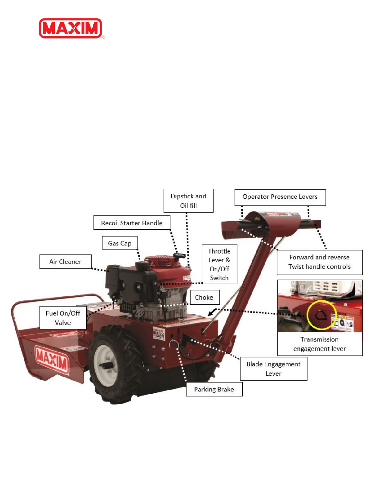
1.6 Control and Adjustment Locations
Familiarize yourself with the location of various controls and adjustments located on the unit.
Page 9

MBC190H
800-621-2789 MBC190H Rev A Page 9
1.7 Model Identification
Please fill in your model and serial number below for future reference. This will help assist in
prompt service when ordering parts and service from your local Maxim Dealer.
Brush Mower Model No.___________________ Brush Mower Serial No. __________________
Engine Model No.__________________ Engine Serial No. _____________________________
Refer to the image below for location of your serial number plate:
Please complete the Warranty/Product Registration at the time of purchase. You will need to
complete the warranty/product registration form (pg. 37) with your new unit, or you may visit our
website www.maximmfg.com and complete our online product registration form. We require
this information so we can keep you updated with any important information about your Maxim
Brush Cutter and provide you with the best customer service possible.
Contact your local Maxim Dealer for OEM replacement parts or contact our customer service
department for assistance in parts, locating your local servicing dealer and more. Your local dealer
is equipped and trained to handle service and repair for your Brush Cutter.
1.8 Further Assistance
Your dealer and all of us at Maxim want you to be pleased with your Brush Cutter. Should you
require further assistance or have questions regarding your Brush Cutter, please contact your
local dealer where you purchased your Brush Cutter. If you are unable to satisfy your needs by
your local dealer, please contact us at:
Maxim
20195 South Diamond Lake Road, STE 100
Rogers, MN 55374
800-621-2789
www.maximmfg.com
Page 10

MBC190H
800-621-2789 MBC190H Rev A Page 10
2 SAFETY
2.1 General Safety Rules
• Read, understand, and follow all instructions on the machine and in the manual(s). Be
thoroughly familiar with the controls and proper use of the machine before starting.
• Disengage all controls before starting the engine (motor).
• Use this equipment for its intended purpose only.
• Familiarize yourself with all the safety and operating decals on this equipment.
• Stop the engine (motor) when leaving the operating position.
• Do not put hands or feet near or under rotating parts.
• Only allow responsible individuals who are familiar with the instructions to operate the
machine. Do not allow children to operate this machine. Do not allow adults to operate
the machine without proper instruction.
• Thoroughly inspect the area where the machine is to be used and remove all foreign
objects. Your mower can propel small objects at high-speed causing personal injury or
property damage. Stay away from breakable objects, house windows, automobiles, etc.
• Wear appropriate clothing such as sturdy, rough-soled shoes (steel toe recommended)
and close-fitting pants and shirt. Never wear sandals, sneakers, or open shoes, and never
operate the machine with bare feet.
• Never leave the engine/mower running and unattended. Turn off blade, set parking
brake, and stop engine before leaving the machine.
• Always wear safety goggles or safety glasses with side shields when operating the
machine to protect your eyes from foreign objects which can be thrown from the unit.
• Always wear a protective hearing device.
• Always wear work gloves and sturdy rugged soled footwear. Wear footwear that will
improve footing on slippery surfaces.
• It is advisable to wear protective headgear to prevent the possibility of being struck by
small flying particles, or being struck by low hanging branches, twigs or other objects
which may be unnoticed by the operator.
• Do not operate the machine without proper guards or safety protective devices in place.
• Operate only in daylight.
• Stop and do not operate if someone approaches.
• Do not operate product when fatigued or under the influence of alcohol, drugs or other
medication which can cause drowsiness or affect your ability to operate machine safely.
• Watch for traffic when operating the Brush Cutter near, or when crossing roads.
• If the equipment should start to vibrate abnormally, stop the engine (motor), push down
the throttle lever located on the engine to the OFF position.
• Regularly inspect the machine. Make sure parts are not bent, damaged or loose.
• Temperature of muffler and nearby areas may exceed 150° F (65° C). Allow muffler and
engine areas to cool before touching.
Page 11

MBC190H
800-621-2789 MBC190H Rev A Page 11
• Prolonged exposure to noise and vibration from gasoline engine-powered equipment
should be avoided. Take intermittent breaks and wear ear protection from engine noise
as well as heavy work gloves to reduce vibration in hands.
• Keep all screws, nuts, and bolts tight.
• Do not transport the machine from one place to another with the engine running.
• Disconnect transmission engagement lever on right side of unit base, see page 8.
• Always turn off fuel supply valve on engine before transport, see page 8.
• Check local regulations for age restrictions on use of this machine.
2.2 PRODUCT-SPECIFIC SAFETY RULES
• Do not operate the machine on terrain with large rocks and/or foreign objects which can
damage the equipment.
• After striking a foreign object, stop the engine by pushing down the throttle lever, located
on the engine, to the OFF position. Inspect the machine for damage. If damaged, repair
before starting and operating the machine.
• If an object becomes lodged between the blade and the deck, shut off engine by pushing
down the throttle lever, located on the engine to the OFF position and disconnect spark
plug wire to prevent accidental start up. Allow the machine to cool before attempting to
remove the foreign object.
• Keep the area of operation clear of all persons, particularly small children, and pets.
2.3 ENGINE SAFETY PRECAUTIONS
⚠ WARNING
ENGINES GIVE OFF CARBON MONOXIDE, AN ODORLESS, COLORLESS, POISONOUS GAS. CARBON MONOXIDE
MAY BE PRESENT EVEN IF YOU DO NOT SMELL OR SEE ANY ENGINE EXHAUST. BREATHING CARBON MONOXIDE
CAN CAUSE NAUSEA, FAINTING OR DEATH, IN ADDITION TO DROWSINESS, DIZZINESS AND CONFUSION.
IF YOU EXPERIENCE ANY OF THESE SYMPTOMS, SEEK FRESH AIR AND MEDICAL ATTENTION IMMEDIATELY.
⚠ CAUTION
HOT GASES ARE A NORMAL BY-PRODUCT OF A FUNCTIONING INTERNAL COMBUSTION ENGINE. FOLLOW ALL
SAFETY INSTRUCTIONS TO PREVENT BURNS AND FIRES.
DO NOT ALTER/MODIFY ENGINE:
NEVER ALTER OR MODIFY THE ENGINE FROM THE FACTORY. SERIOUS INJURY OR DEATH MAY OCCUR IF ENGINE
IS MODIFIED OR ALTERED.
WHEN WORKING ON OR REPLACING PARTS FOR THE ENGINE OR PRODUCT, YOU MUST SHUT OFF ENGINE BY
PUSHING DOWN THE THROTTLE LEVER, LOCATED ON THE ENGINE TO THE OFF POSITION.
Page 12

MBC190H
800-621-2789 MBC190H Rev A Page 12
PREVENTING CARBON MONOXIDE POSIONING
• Always start and run engine outdoors. Do not start or run engine in an enclosed area,
even if doors or windows are open.
• Never try to ventilate engine exhaust indoors. Carbon monoxide can reach dangerous
levels very quickly.
• Never run engine outdoors where exhaust fumes may be pulled into a building.
• Stop the engine (motor) when leaving the operating position.
• Never run engine outdoors in a poorly ventilated area where the exhaust fumes may be
trapped and not easily taken away. (Examples include in a large hole or areas where hills
surround your working area.)
• Never run engine in an enclosed or partially enclosed area. (Examples include buildings
that are enclosed on one or more sides, under tents, car ports or basements.)
• Do not change the engine governor settings or over-speed the engine.
GASOLINE FIRES AND HANDLING FUEL SAFELY
⚠ Warning gasoline is highly flammable and explosive
You can be burned or seriously injured when handling fuel. Use extreme care when handling
gasoline. They are flammable and vapors are explosive.
• When storing extra fuel be sure that it is in an appropriate
container and away from any fire hazards.
• Prevent fire and explosion caused by static electric discharge.
Use only nonmetal, portable fuel containers approved by the
Underwriter’s Laboratory (U.L.) or the American Society for
Testing & Materials (ASTM).
• Always fill fuel tank outside in a well-ventilated area. Never fill
fuel tank with fuel indoors. (Examples include basement, garage,
barn, shed, house, porch, etc.) Never fill tank near appliances
with pilot lights, heaters, or other ignition sources. If the fuel
must be drained, this should be done outdoors. The drained fuel should be stored in a
container specifically designed for fuel storage or it should be disposed of carefully.
• Never remove the fuel cap or add fuel with the engine running. Stop engine and allow to
cool before filling.
• Do not smoke while using engine or around fuel.
• Never drain fuel from engine in an enclosed area.
• Do not store engine with fuel in fuel tank indoors. Fuel and fuel vapors are highly
explosive.
Page 13

MBC190H
800-621-2789 MBC190H Rev A Page 13
• Always wipe up excess (spilled) fuel from engine before starting. Clean up spilled fuel
immediately. If fuel is spilled, do not start the engine, but move product and fuel
container from area. Clean up spilled fuel and allow to evaporate and dry after wiping and
before starting.
• Allow fuel fumes/vapors to escape from the surrounding air before starting the engine.
• Test the fuel cap for proper installation before starting and using engine.
• Always run the engine with fuel cap properly installed on the engine.
• Never smoke while refilling engine fuel tank.
• Never pour fuel from engine fuel tank.
• Never siphon fuel by mouth to drain fuel tank.
• Always have an adult fill the fuel tank and never allow children to fill the engine.
• Never allow anyone under the influence of drugs or alcohol to fill the engine.
• When storing gasoline or equipment with fuel in the tank, store away from furnaces,
stoves, water heaters or other appliances that have a pilot light or other ignition source
because they can ignite gasoline vapors.
BURNS AND FIRES
The muffler, muffler guard and other parts of the engine become extremely hot during the
operation of the engine. These parts remain extremely hot after the engine has stopped.
• Never remove the muffler guard from the engine.
• Never touch the muffler guard because it is extremely hot and will cause severe burns.
• Never touch parts of the engine that become hot after operation.
• Always keep materials and debris away from the muffler guard and other hot parts of the
engine to avoid fires.
CHILDREN AND BYSTANDERS
Tragic accidents can occur if the operator is not alert to the presence of children and/or
bystanders. Never assume that others will remain where you last saw them.
• Keep the area of operation clear of all persons, especially small children, and pets.
• Keep children under the watchful care of a responsible adult.
• Be alert and turn machine off if children enter the area. Shut off engine by pushing down
the throttle lever, located on the engine to the OFF position.
• Before and while moving backwards, look behind and down for small children.
• Never allow children to operate the machine.
• Use extra care when approaching blind corners, shrubs, trees, or other objects that may
obscure vision.
Page 14

MBC190H
800-621-2789 MBC190H Rev A Page 14
SERVICE
• Always stop the engine whenever you leave the equipment, before cleaning, repairing, or
inspecting the unit. Engine should be turned off and cool. Never make adjustments or
repairs with the engine (motor) running. Shut off engine by pushing down the throttle
lever, located on the engine to the OFF position.
• Disconnect the spark plug wire and keep the wire away from the plug.
• Always wear eye protection when you make adjustments or repairs.
• Keep all nuts and bolts tight and keep equipment in good condition.
• Never tamper with safety devices. Check their proper operation regularly.
• To reduce fire hazard, keep machine free of grass, leaves or other debris build-up. Clean
up oil or fuel spillage. Allow machine to cool before storing.
• When servicing or repairing the machine, do not tip the machine over or up unless
specifically instructed to do so in this manual. Service and repair procedures can be done
with the machine in an upright position. Some procedures will be easier if the machine is
on a raised platform or working surface.
• Stop and inspect the equipment if you strike an object. Repair, if necessary, before
restarting.
• Clean and replace safety and instruction decals, as necessary.
• To help extend engine life, always have engine air filter mounted and clean.
• Inspect machine before storage. When not in use, shut off engine by pushing down the
throttle lever, located on the engine to the OFF position. and store indoors in a dry place
locked or otherwise inaccessible to children.
• Use only original equipment parts from the factory, including all nuts and bolts.
2.4 Safety Decals
This Brush Cutter has been designed and manufactured to provide you the safety and reliability
you would expect from an industry leader in outdoor power equipment manufacturing.
Reading this manual and the safety instructions it contains will provide you with the necessary
basic knowledge to operate this equipment safely and effectively. We have placed safety decals
on the Brush Mower, to remind you of some of this important information while you are
operating the unit.
These important safety decals are illustrated below and are shown here to help familiarize you
with the content of the safety messages you will see as you perform normal mowing operations.
Please review these decals now, and if you have any questions regarding its meaning or how to
comply with these instructions, reread the complete safety instruction text in this manual, or
contact your local dealer.
Page 15

MBC190H
800-621-2789 MBC190H Rev A Page 15
Should a decal become unreadable because of being worn, faded or otherwise damaged during
the use of your Brush Cutter; please use the part number information provide to order a
replacement label. These decals are easily applied and will act as a constant visual reminder to
you, and others who may use the equipment, to follow the safety instructions necessary for safe,
effective operation of your Brush Cutter.
2.5 Training
1. Read the Owner’s Manual carefully. Be thoroughly familiar with the controls and the
proper use of the equipment. Know how to stop the unit and disengage the blade quickly.
2. Never allow children to operate the equipment. Never allow adults to operate the
equipment without proper instructions.
3. Keep the area of operation clear of all persons, particularly small children, and pets.
4. Always stay alert. Watch what you are doing and use common sense. Do not operate unit
when fatigued.
5. Understand the use of all Brush Cutter controls.
ITEM # ZUMBC190H - Complete Decal Sheet
Page 16

MBC190H
800-621-2789 MBC190H Rev A Page 16
2.6 Preparation
1. Thoroughly inspect the area where the equipment is to be used and remove all foreign
objects.
2. Disengage the blade before starting the engine by moving the Blade engagement lever to
the left and lower.
3. Always wear substantial footwear and long pants. Do not operate the equipment when
barefoot or wearing open sandals.
4. Wear ear and eye protection. Eye protection must meet applicable CE requirements. To
avoid hearing damage, we recommend hearing protection be worn whenever using the
equipment.
5. Handle fuel with care; it is highly flammable.
6. Use an approved fuel container.
7. Never add fuel to a running engine or hot engine.
8. Fill fuel tank outdoors with extreme care. Never fill fuel tank indoors.
9. Replace gasoline cap securely and clean up spilled fuel before starting.
10. Never attempt to make any adjustments while the engine is running. Shut off engine by
pushing down the throttle lever, located on the engine to the OFF position.
2.7 Operation
1. Do not put hands or feet near or under rotating parts.
2. Stop and do not operate if someone approaches.
3. Never leave the engine/mower running and unattended.
a. Disengage blade and wait until the blade stops.
b. Shut off engine by pushing down the throttle lever, located on the engine to the
OFF position.
c. Set parking brake
4. Exercise extreme caution when operating near gravel drives, walks, or roads. Stay alert for
hidden hazards or traffic.
5. Do not carry passengers.
6. Do not operate on slopes if uneasy or uncertain about the machine stability.
7. After striking a foreign object, shut off engine by pushing down the throttle lever, located
on the engine to the OFF position, thoroughly inspect the mower for any damage, and
repair the damage before restarting and operating.
8. Exercise caution to avoid slipping or falling.
9. If the unit should start to vibrate abnormally or make unusual noise, stop the engine by
pushing down the throttle lever, located on the engine to the OFF position. Allow at least
5 minutes to cool prior to any inspection or service. Vibration is generally a warning of
trouble.
10. Before cleaning, repairing, or inspecting, shut off the engine and make certain all moving
parts have stopped. Disconnect the spark plug wire and keep the wire away from the plug
to prevent accidental starting.
Page 17

MBC190H
800-621-2789 MBC190H Rev A Page 17
11. Do not run the engine indoors; exhaust fumes are dangerous.
12. Never modify the mower deck or operate the mower without proper guards, or other
safety protective devices in place.
13. Keep children and pets away when operating.
14. Do not overload the machine capacity by attempting to mow too fast or cutting too large
diameter of brush, saplings.
15. Never operate the machine at high speeds on slippery surfaces. Look behind and use care
when backing up.
16. Never operate the mower without good visibility or light.
17. Never allow the mower to ride up on a tree or sapling, in an attempt to cut. If it does not
bend over in the normal mowing position, deck on ground, then it is too large to cut.
2.8 Storage
1. Keep machine, attachments, and accessories in safe working conditions.
2. Check blade and engine mounting bolts, and other bolts for proper tightness to be sure
the equipment is in safe working condition.
3. Check for Hydraulic leaks.
4. Never store the machine with fuel in the fuel tank inside a building where ignition sources
are present, such as hot water and space heaters, clothes dryers, etc. allow the engine to
cool before storing in any enclosure.
5. Fuel stabilizer is an acceptable alternative in minimizing and formation of fuel gum
deposits during storage. Run engine at least 10 minutes after adding stabilizer to allow
the stabilizer to reach the carburetor. It is not necessary to drain either carburetor or fuel
tank when using fuel stabilizer.
6. Touch up all rusted or chipped paint surfaces, sand lightly before painting.
7. If possible, store your unit indoors and once sufficiently cooled, cover it to give protection
from the elements.
Page 18

MBC190H
800-621-2789 MBC190H Rev A Page 18
3 PARTS BREAKDOWN
3.1 Breakdown
Page 19

MBC190H
800-621-2789 MBC190H Rev A Page 19
Ref
Part Number
Description
Qty 1 1110200.MAX
Main Frame Belt Housing
1 2 1110201.MAX
Deck - Blade Guard
1 3 1110202.MAX
Front Cover
1 4 1110203.MAX
Engine Mount Plate
1 5 1110204.MAX
Cover, Rear
1 6 GXV390
Honda, GXV390 Engine
1 7 1110205.MAX
Transaxle - wheel drive
1 8 1110206.MAX
Handle Bracket
1 9 1110207.MAX
Handle Weldment
1
10
1110208.MAX
Cutting Blade, 26"
1
11
1110209.MAX
Handle Cover
1
12
1110144.MAX
Rim, 8 x 3.75-Tire, 480 x 8 4ply
2
13
1110210.MAX
Spindle Housing
1
14
1110211.MAX
Blade Spindle
1
15
1110212.MAX
Pulley, Blade Drive, 8 x 3/4"
1
16
1110213.MAX
Nut, Blade Spindle, 3/4
2
17
1110214.MAX
Blade Spindle Bearing (Top & Bottom)
2
18
1110215.MAX
Blade Washer, Stepped, Upper
1
19
1110216.MAX
Blade Washer, Lower
1
20
1110217.MAX
Washer, Star 3/4"
1
21
1110218.MAX
Blade Belt
1
22
1110219.MAX
Transaxle Belt
1
24
1110220.MAX
Clutch Brake
1
25
1110221.MAX
Clutch Spring
1
26
1110222.MAX
S Hook 1-1/8"
2
27
1110223.MAX
Spring, extension
3
28
1110224.MAX
Anti-rotation Rod
1
29
1110225.MAX
Anti-rotation Bracket
1
30
1110226.MAX
Spacer, Spindle
1
31
1110227.MAX
Throttle Lever/Bracket Kit
1
36
1110232.MAX
Wire Harness - Micro SW to Engine
1
37
1110233.MAX
Wire Harness - Safety SW to Micro SW
1
38
1110234.MAX
Control Rod, Wheel Drive
1
39
1110094.MAX
Drive rod End, 3/8-16
1
40
1110109.MAX
Serrated Flange Nut, 3/8-24 Control Rod
End 1 41
1110112.MAX
Ball Joint stud, 3/8-24
1
42
1110235.MAX
Connecting rod, Transaxle
1
43
1110236.MAX
Control Rod Pivot Bracket
1
45
1110237.MAX
Shoulder Bolt, 3/8 x 3 3/4"
1
46
1110238.MAX
Microswitch, Blade Engage safety
1
47
1110239.MAX
Blade Engagement Lever
1
48
1110240.MAX
Compression Spring, Blade Engage
Handle
1
49
1110052.MAX
Safety Switch, Handlebar (Black, normally
Closed)
2
50
1110065.MAX
Drive Control safety Paddle
2
51
1110093.MAX
Handle Grip, 7/8"
2
53
1110042.MAX
Handlebar
1
54
1110241.MAX
Drive Control Stop Collar
2
55
1110242.MAX
Handle Cover Bracket
1
56
1110243.MAX
Debris Safety Flap
1
57
1110244.MAX
Debris Flap Hinge
1
58
1110245.MAX
Eye Bolt, 1/4-20 x 2
3
59
1110246.MAX
Wheel Hub
2
60
1110247.MAX
Split ring, 2"
1
61
1110248.MAX
Park Brake Chain
1
62
1110249.MAX
Transaxle Support Bracket
1
63
1110250.MAX
E-clips
2
64
1110251.MAX
Caps, Axle
2
65
1110252.MAX
Hub Washer
2
66
1110253.MAX
Key, 3/16 x 2 1/4"
2
67
1110254.MAX
Skid Plate
1
68
1110255.MAX
Rod, Deck chain retainer
1
69
1110256.MAX
Rod, Freewheel Engage
1
70
1110257.MAX
Deck Chain - 5-link
27
71
1110061.MAX
Cotter Pin, 1/8 x 1 1/4"
3
72
1110258.MAX
Belt Idler Pulley
1
73
1110259.MAX
Idler Pulley Spring
1
74
1110260.MAX
Idler Pulley Arm
1
75
1110261.MAX
Grip, 1/4 x 1 Handle
1
76
1110054.MAX
Valve Stem
2
77
1110073.MAX
Serrated Flange Nut 1/4-20
10
78
1110075.MAX
Serrated Flange Bolt 1/4-20 x 1/2"
11
79
1110262.MAX
Flange bolt, 1/4-20 x 3/4
5
80
1110080.MAX
3/8" Nylon Lock Nut
2
81
1110263.MAX
Flange Bolt 3/8-16 x 1
4
84
1110085.MAX
Serrated Flange Nut 5/16-18
24
85
1110265.MAX
Flange Bolt, 5/16-18 x 3/4
16
86
1110113.MAX
Serrated Flange Nut 3/8-16
8
87
1110266.MAX
carriage bolt, 1/4-20 x 3/4
3
88
1110267.MAX
5/16-18 x 2 1/4 flange Bolt
4
Page 20

MBC190H
800-621-2789 MBC190H Rev A Page 20
89
1110268.MAX
8-32 x 5/8 Truss Head Mach screw
5
90
1110269.MAX
8-32 Nylon Locknut
5
91
1110270.MAX
1/4-20 x 1 1/2 Flange Bolt
1
92
1110271.MAX
1/4" Flat washer
1
93
1110272.MAX
HH Bolt, 3/8-16 x 3
1
94
1110273.MAX
HH bolt 5/16-24 x 1
2
95
1110274.MAX
HH Bolt, 5/16-18 x 1 1/2
3
96
1110275.MAX
Flange Bolt 3/8-16 x 3/4
4
97
1110276.MAX
Nut, 1/4-20 Reversable Lock
1
98
1110277.MAX
Collar, Head
1
99
1110278.MAX
washer, 7/16 lock
1
100
1110279.MAX
Bushing, 3/8 Control Rod Pivot
1
101
1110280.MAX
S-Hook, 1-7/8"
1
102
1110281.MAX
Grease Fitting - Spindle Housing
1
104
1110282.MAX
Bolt, 7/16-20 x 3 1/2
1
105
1110283.MAX
Lug Nut - 1/2"
8
106
1110095.Max
Hairpin Cotter 1/4"
1 ZUMBC190H
Decal Sheet
1
Page 21

MBC190H
20195 South Diamond Lake Road, STE 100
Rogers, MN 55374
800.621-2789
21
3.2 General Information
4 ASSEMBLY
Your Brush Cutter comes fully assembled with the exception of mounting the handle to the frame
and the connection of one wire, see next page for further instructions. The engine on this Brush
Cutter, is shipped from the factory, without engine oil.
You MUST fill the engine to its proper level, see page 34
Engine
Honda GXV390, 389cc
Transmission
Hydro transaxle w/Enhanced Traction Control
Blade Drive
V-Belt
Engagement
Manual clutch (self-Adjusting)
Tire Size
4.80/4.00 – 8 Pneumatic Bar Lug
Ground Speed
Variable, max. 4 mph
Cutting Width
26"
Blade
Dual Sided, Reversible
Forward/Reverse
Twist Handle Hydro Controls
Operator Present Safety
Yes
Deck
10 Gauge Steal
Engine Start
Recoil
Length
70"
Height
41"
Width
29"
Weight
300 Lbs.
Warranty
12 - Months
Maximum Cut Sapling Diameter
2"
Sealed Spindle Bearings
Yes
Spindle Size
3/4
Page 22

MBC190H
20195 South Diamond Lake Road, STE 100
Rogers, MN 55374
800.621-2789
22
Page 23

MBC190H
20195 South Diamond Lake Road, STE 100
Rogers, MN 55374
800.621-2789
23
4.1 Final Set-up
Engine Oil:
•
The engine of your unit has been shipped, from the factory, without engine oil. You
MUST fill the engine to its proper level, see page 34.
•
With engine level, clean area around oil fill tube and remove plug.
Page 24

MBC190H
20195 South Diamond Lake Road, STE 100
Rogers, MN 55374
800.621-2789
24
•
With engine level, oil should be at the upper level of the Oil dipstick. For oil
specifications and capacity see your Honda engine manual shipped with unit.
•
Fill engine with oil and reinstall engine oil cap and tighten.
•
To change engine oil, see the Maintenance section in this manual.
Fuel:
• Fill the fuel tank. Use clean, fresh, lead-free
gasoline. DO NOT MIX OIL WITH GASOLINE.
• Fill fuel tank to bottom of filler neck. Do not
overfill. Use fresh, clean, regular unleaded
gasoline with a minimum of 87 octane. (Use of
leaded gasoline will increase carbon and lead
oxide deposits and reduce valve life). Do not mix
oil with gasoline. Purchase fuel in quantities that
can be used within 30 days to assure fuel
freshness.
Tires:
• Check tire pressure
• Inflate tires to 39 psi
a) Note: New tires are overinflated in order to properly seat the bead to the
rim.
⚠ CAUTION
CAUTION: Fill to within 1/2 inch of top of fuel tank to prevent spills and to allow for fuel
expansion. If gasoline is accidentally spilled, move machine away from area of spill. Avoid
creating any source of ignition until gasoline vapors have disappeared.
Wipe off any spilled oil or fuel. Do not store, spill, or use gasoline near an open flame.
Gasoline is highly flammable and explosive, you can be burned or seriously
injured when handling fuel. Use extreme care when handling gasoline or other
fuels. They are flammable and vapors are explosive.
Page 25

MBC190H
20195 South Diamond Lake Road, STE 100
Rogers, MN 55374
800.621-2789
25
5 OPERATING CONTROLS
5.1 To Start Engine
When starting the engine for the first time or if engine has run out of fuel it will take extra
pulls of the recoil starter to move fuel from the tank to the engine.
1. If engine is cold, pull-out Choke lever control rod, located on the back of the engine
towards the handlebars.
2. Pull Throttle control lever up, located on the back of the engine towards the handlebars
halfway between slow and fast.
3. Turn fuel shut-off valve, located on engine, to open position.
4. Grasp recoil starter grip and pull slowly until the starter recoil engages and
begins to turn the engine.
5. Pull recoil cord rapidly to start engine. Do not let starter handle/rope snap back
against starter.
6. If engine fires, but does not start, push choke control rod to half choke position.
Pull recoil starter handle until engine starts.
7. When engine starts, slowly push choke control rod in to “RUN” position as
engine warms up.
8. Move throttle control, located on engine, to desired running position.
9. Allow engine to warm up for a few minutes before engaging blade.
⚠ CAUTION
Keep Blade in the “DISENGAGED” position when starting engine.
⚠ CAUTION
READ THIS OWNER’S MANUAL AND SAFETY RULES
BEFORE OPERATING YOUR BRUSH MOWER.
Compare the illustrations in this manual with your Brush mower, to
familiarize yourself with the location of various controls and
adjustments. Save this manual for future reference.
Page 26

MBC190H
20195 South Diamond Lake Road, STE 100
Rogers, MN 55374
800.621-2789
26
6 MACHINE IDENTIFICATION COMPONENTS
7 OPERATION
7.1 Drive operation and Operator Presence Levers
1. With hands on handlebar, gripping the Operator Presence Levers/Micro safety switch
tabs, unit can be operated in forward/reverse by twisting handle.
2. Twist handlebar control forward for Forward drive, twist control backward for Reverse
drive. Center control for Neutral operation.
3. Groundspeed increases with more twist.
7.2 Operator Presence Levers
1. Located above the outer ends of both right and left handles.
2. One lever must be held down in order to engage the blade.
3. Should operator have blade engaged and release both handles, engine will stop.
Page 27

MBC190H
20195 South Diamond Lake Road, STE 100
Rogers, MN 55374
800.621-2789
27
7.3 Blade Engagement
1. While in operator’s zone with one hand on handle holding minimum of one presence
lever down, increase engine throttle to 3/4 or more.
2. Lift blade engagement lever up and towards the right to lock in.
3. To stop blade, move engagement lever to the left and lower.
7.4 Transporting – pushing Brush Cutter without engine running/power
1. Pull Transmission engagement lever out, to disconnect powertrain and to operate
manually. See section 8.1 for additional information.
2. Push Transmission engagement lever in, to reconnect powertrain to be Engine driven.
7.5 Parking Brake
1. Parking Brake is engaged when the Large loop of the chain is pulled outward until taut.
2. Engage chain in keyhole slot to secure
3. To disengage, slide chain up and out of slot and release allowing chain to move inward.
7.6 Cutting/Mowing
•
Only allow responsible individuals who are familiar with the instructions to operate the
machine. Do not allow children to operate this machine. Do not allow adults to operate
the machine without proper instruction.
• Thoroughly inspect the area where the machine is to be used and remove all foreign
objects. Your equipment can propel small objects at high-speed causing personal injury or
property damage. Stay away from breakable objects, such as house windows,
automobiles, greenhouse, etc.
• Always wear safety goggles or safety glasses with side shields when operating the
machine to protect your eyes from foreign objects which can be thrown from the unit.
• Never leave the engine/mower running and unattended. Turn off blade, set parking
brake, and stop engine before leaving the machine.
• Operate only in daylight.
• If the equipment should start to vibrate abnormally, stop the engine (motor), push down
the throttle lever located on the engine to the OFF position.
• Watch for traffic when operating the Brush mower near, or when crossing roads.
• Exercise extreme caution when operating near gravel drives, walks, or roads. Stay alert for
hidden hazards or traffic.
• Do not operate on slopes if uneasy or uncertain about the machine stability.
• Do not overload the machine capacity by attempting to cut/mow too fast or cutting too
much or too large diameter of brush, saplings.
Page 28

MBC190H
20195 South Diamond Lake Road, STE 100
Rogers, MN 55374
800.621-2789
28
8 Transporting – pushing Brush Cutter manually without engine
running/power
8.1 Transporting – Free Wheel
1. Pull Transmission engagement lever out to disconnect powertrain and to operate
manually.
2. Push Transmission engagement lever in to reconnect powertrain and to be Engine
driven.
9 MAINTENANCE AND LUBRICATION
• The warranty on this Brush Cutter does not cover items that have been subjected to
operator abuse or negligence. To receive full value from the warranty, the operator must
maintain mower as instructed in this manual.
• BEFORE EACH USE
1.
Check engine oil level. See page 34.
2.
Check blade engagement operation.
3.
Check operator’s presence levers for proper operation.
4.
Check for loose fasteners.
Pull looped transmission
engagement handle out away
from frame to dis-engage
transmission which will allow
mower to Free Wheel
Pull outward
Page 29

MBC190H
20195 South Diamond Lake Road, STE 100
Rogers, MN 55374
800.621-2789
29
9.1 Mower Blade
1. Make certain that engine is cool, and the spark plug wire is disconnected to prevent
accidental starting.
2. Check condition of blade being certain it is not damaged and is sharp.
3. If blade needs to be removed:
a. Tip the mower back and block up the front of the deck
b. Place one wrench on the hex nut securing blade
c. Place a wooden block between the tip of the blade and side of deck to keep the
blade from turning.
d. NOTE: Blade nut is a Standard Right-Hand Thread
e. Inspect blade – Rotate to other side for fresh edge - Sharpen – Or Replace
f. Mount blade in reverse order
9.2 Mower Transmission belt
1. Make sure engine is cool and the spark plug wire is removed to prevent accidental
starting.
⚠ CAUTION
Process to remove blade can be dangerous. Unit is heavy and needs to be
secure and stable when tipped back for service. Blade is sharp, take extra
caution not to spin blade during removal of center nut.
Front Belt Cover
Engine Mounting
Plate
Rear Cover
Page 30

MBC190H
20195 South Diamond Lake Road, STE 100
Rogers, MN 55374
800.621-2789
30
2. Loosen only, 4 bolts holding Engine Mounting plate.
3. Remove bolts:
a. 4 holding the Front belt cover
b. 2 holding Rear cover
4. Remove Front belt cover will help lighting, seeing components and accessibility.
5. Removing small rear panel will help lighting, seeing components and accessibility.
6. Release the tension of the Blade belt by using a 9/16 socket wrench on Idler pulley
center mounting bolt and pull back the idler pulley and slip the Blade drive belt off.
7. Slide Engine mounting plate forward to release Transmission belt tension. From
under the unit, slip the belt down over the Engine driven pulley, and up and over the
Transmission pulley to entirely remove.
8. Reinstall Transmission belt and place within the Engine driven pulley and the
Transmission pulley grooves using the above steps in reverse order.
Page 31

MBC190H
20195 South Diamond Lake Road, STE 100
Rogers, MN 55374
800.621-2789
31
9. Slide Engine mounting plate towards the rear of the mower, to tighten Transmission
Belt. Pull the Engine plate to the rear while tightening the four mounting bolts.
10. Remount small panel and hardware
11. Resecure Belt tension by placing the back side of the Blade belt behind the Idler
pulley as noted in step 6.
12. Remount Front belt cover and hardware.
9.3 Mower Blade Belt
Steps to remove the Blade drive belt:
First follow steps 1-7, in 9.2 section above. The Transmission belt needs to be
removed as a part of the process ahead of the Blade belt replacement, do so and then
follow these steps:
1. Through the Rear cover opening, remove the Pivot bolt and spring engagement lever
friction nut, compression spring & bolt located under the Engine mounting plate.
2. Lower Blade engagement lever.
3. Slide Engine mounting plate to the rear and disconnect Blade engagement lever
spring from under the unit.
Page 32

MBC190H
20195 South Diamond Lake Road, STE 100
Rogers, MN 55374
800.621-2789
32
4. Through the Rear cover opening, lower the Anti rotation bracket by removing the
center bolt and the right rear engine mounting bolt. It is NOT necessary to remove
adjuster bolt from the Clutch to the Anti rotation bracket.
5. Lower Blade belt, over clutch and guide it around the Anti rotation bracket to remove.
6. It may be necessary to rotate the top of the Anti-rotation bracket towards the back,
until there is enough space to remove the belt from the clutch.
7. Reinstall Blade belt into clutch pulley groove and in reverse order, reassemble – along
with remounting the Anti rotation bracket.
8. Re-mount the Blade Engagement spring.
9. Reinstall the Blade engagement lever, friction nut, compression spring & bolt. Tighten
only enough for friction slippage.
10. Slide Engine mounting plate forward and install Transmission belt.
11. Slide Engine mounting plate towards the rear of the mower, to tighten Transmission
Belt. Pull the Engine plate to the rear tightening the Transmission belt as you tighten
the four mounting bolts.
12. Make certain the Blade belt goes around both the clutch and the front blade pulley.
13. Using a 9/16 socket wrench on Idler pulley center mounting bolt, pull back the idler
pulley and slip the belt into place with the Idler pulley running on the back side of the
Blade belt. Once in position release wrench and allow the Idler pulley/bracket spring
to hold it tight.
14. Replace covers and hardware to complete belt replacement.
Page 33

MBC190H
20195 South Diamond Lake Road, STE 100
Rogers, MN 55374
800.621-2789
33
9.4 Mower Blade Belt tension
1. The tension of the Blade drive belt, between two pulleys should be adjusted to, with a
ten-pound pull, have a deflection of ½”
9.5 Cleaning your Brush Cutter
IMPORTANT: If the engine has been running, allow it to cool for at least half an hour before
washing.
1. Wash the Brush Cutter, including the underside, after use. Also clean under the deck
cover. Allow the mower to dry before use.
2. Use Compressed air and/or wash the engine by hand and be careful to prevent water or
debris from entering the air cleaner.
NOTE: Do not use a garden hose or pressure washing equipment, it can force water into the
air cleaner. Water in the air cleaner will soak the filter element and can enter the carburetor or
engine cylinder, causing damage.
3. After washing the Brush Cutter, wipe dry.
4. After the mower is clean and dry, touch up any damaged paint and coat other unpainted
areas with a light film of oil.
9.6 Cleaning the Cooling System
1. Remove blower housing and clean regularly.
NOTE: Grass or chaff may clog cooling system after prolonged service. Continued operation
with a clogged cooling system causes severe overheating and possible engine damage.
9.7 Dual Filter Element Air Cleaner
Air Cleaner Check/Cleaning and Replacement
Dual Element Type:
A dirty air filter will restrict air flow to the carburetor
reducing engine performance. If the engine is operated
in dusty areas, clean the air cleaner more often than
specified in the MAINTENANCE SCHEDULE.
Operating the engine without the air filters or with the
filters installed loosely, will allow dirt to enter the engine,
causing rapid engine wear. Install the air filter securely.
1.
Remove the nut (1) and the air cleaner cover (2).
2.
Remove the wing nut (3) and the air filter assembly
(4-5)
3.
Separate the inner filter (Paper) (4) from the outer filter (foam) (5). Carefully
check both filters for holes and tears and replace if damaged.
4.
Clean filters if they are to be reused.
5.
Install the elements in the reverse order of removal.
Page 34

MBC190H
20195 South Diamond Lake Road, STE 100
Rogers, MN 55374
800.621-2789
34
9.8 Engine Oil – 1.2 quart, (38.4 oz)
Use only high-quality detergent oil related with API service classification SG, SF. Select the oil’s
SAE viscosity grade according to your expected temperature.
Use the Oil dipstick and check engine oil level before each use, fill to the upper level of the Oil
dipstick as indicated below.
Change the oil after the first 20 hours of operation and then every 100 hours after or at least
twice a year.
TO CHANGE ENGINE OIL
1 Be sure engine is shut off and level.
2 Oil will drain more freely when warm.
3 Use a funnel to prevent oil spill and catch
oil in a suitable container.
4 Remove Oil filler cap/dipstick and drain
plug.
5 After oil has drained completely, replace
oil drain plug, and tighten securely.
6 Be careful not to allow dirt to enter the
engine at Oil filler location.
7 Add 12.0-13.5 oz of fresh new
recommended oil and fill to the upper
level of the Oil dipstick.
9.9 Muffler
Do not operate tiller without muffler. Do not tamper with exhaust system. Damaged mufflers
or spark arresters could create a fire hazard. Inspect periodically and replace if necessary. Your
engine is equipped with a spark arrester screen assembly, remove every 50 hours for cleaning
and inspection. Replace if damaged.
Page 35

MBC190H
20195 South Diamond Lake Road, STE 100
Rogers, MN 55374
800.621-2789
35
CAUTION:
When mounting tires, unless beads are seated,
over-inflation can cause an explosion.
!
9.10 Spark Plug
Replace spark plug at the beginning of each season or after every 100 hours of use, whichever
comes first. Spark plug gap setting is to .028-0.031” / 0.7-0.8 mm
10 Tire Care
•
Check that lug nuts are tight
•
Maintain 39 pounds of tire pressure.
•
Note: New tires are overinflated at the factory in order to properly seat the bead to
the rim when newly installed.
•
Keep tires free of gasoline or oil which can damage rubber.
10.1 Maintenance Schedule
Page 36

MBC190H
20195 South Diamond Lake Road, STE 100
Rogers, MN 55374
800.621-2789
36
11 WARRANTY
11.1 Warranty/Product Registration
Please register your product immediately after purchase. You can do that by visiting our
website at www.maximmfg.com and complete our online product registration.
Or complete the following warranty/production registration form on the next page and return
to:
Maxim
Attn: Warranty Registration Department
20195 South Diamond Lake Road, STE 100
Rogers, MN 55374
Page 37

MBC190H
20195 South Diamond Lake Road, STE 100
Rogers, MN 55374
800.621-2789
37
Or Fax completed form to 763-428-4821
Page 38

MBC190H
20195 South Diamond Lake Road, STE 100
Rogers, MN 55374
800.621-2789
38
Page 39

MBC190H
20195 South Diamond Lake Road, STE 100
Rogers, MN 55374
800.621-2789
39
(This page intentionally left blank)
Page 40

MBC190H
20195 South Diamond Lake Road, STE 100
Rogers, MN 55374
800.621-2789
40
Maxim
A Brand of Great Northern Equipment Distributing, Inc.
20195 South Diamond Lake Road
Suite 100
Rogers, MN 55374
www.maximmfg.com
800-621-2789
 Loading...