

maxilift M50 Maintenance Manual
Mod. M50
Code MD.0.136 GB Rev 0 Edition 03/07
USE AND MAINTENANCE MANUALUSE AND MAINTENANCE MANUAL
USE AND MAINTENANCE MANUALUSE AND MAINTENANCE MANUAL
USE AND MAINTENANCE MANUAL

Fill in the space below with the required crane identification data.
Code filling example: M50.2H ELH
SERIAL NUMBER: ......................
MANUFACTURING YEAR: ...................
Mark the box regarding the accessories supplied with the crane
ACCESSORIES SUPPLIED WITH THE CRANE
Description YES NO
Electrical winch
Manual winch
Stabilizer
Back load attachment
Quick fitting kit
PRELIMINARY INFORMA TION
Operator’s and Maintenance Manual of MAXILIFT M50 truck loader.
Manual code: MD.0.136 GB
This manual is valid starting from serial no: ....................
Manufacturer: NEXT HYDRAULICS S.r .l.
Via Mediterraneo 6, Boretto (RE)-IT AL Y
In this manual the word “Manufacturer” is referred to “NEXT HYDRAULICS S.r.l.”.
List of documentation supplied along with the loader:
¾ Operator’s and Maintenance Manual (for the end user)
¾ Installation Manual (for the installer and the end user)
A TTENTION
Always carefully read this manual before operating the loader. Most of the accidents occurred during
operations are caused by omission of elementary precautions and non fulfilment of the safety instructions.
Many accidents can be avoided when their causes are well known and relevant adequate
countermeasures are previously taken.
M50 2 H E L H
.
M50 2
.

INDEX
1 FOREWORD -------------------------------------------------------------------------------------------- Page--1
1.1 Remarks ------------------------------------------------------------------------------------------------“----- 1
2 HOW TO CONSUL T THE MANUAL------------------------------------------------------------------- “ ----- 1
2.1 Instructions ------------------------------------------------------------------------------------------------“----- 1
3 CRANE IDENTIFICA TION-------------------------------------------------------------------------------- “ ----- 2
3.1 Identification data--------------------------------------------------------------------------------------------“----- 2
3.3.1 Name plate description ------------------------------------------------------------------------------------“----- 2
3.2 Main crane components identification ------------------------------------------------------------------“-----2
3.3 Crane composition ------------------------------------------------------------------------------------------“ ----- 3
3.4 Accessories ------------------------------------------------------------------------------------------------“ -----4
3.4.1 Winch ------------------------------------------------------------------------------------------------“ -----4
3.4.2 Stabilizers ------------------------------------------------------------------------------------------------“ -----4
4 COMMISSIONING----------------------------------------------------------------------------------------- “ -----5
4.1 Check list before the first commissioning -------------------------------------------------------------“ -----5
4.2 Daily check list ----------------------------------------------------------------------------------------------“ -----5
4.3 CE Certification ----------------------------------------------------------------------------------------------“ -----5
5 GENERAL SAFETY RULES ----------------------------------------------------------------------------- “ ----- 5
5.1 Rules concerning persons---------------------------------------------------------------------------------“ ----- 5
5.2 Rules concerning the crane-------------------------------------------------------------------------------“ -----5
5.3 Rules concerning safety in the traffic -------------------------------------------------------------------“ -----6
6 OPERA TING INSTRUCTIONS-------------------------------------------------------------------------- “----- 7
6.1 Daily check list ----------------------------------------------------------------------------------------------“ -----7
6.2 Loader classification and proper usage ----------------------------------------------------------------“ ----- 7
6.3 Improper usage ----------------------------------------------------------------------------------------------“ -----7
6.4 General attentions ------------------------------------------------------------------------------------------“ -----7
6.5 T en basic rules for the safe loader operator-----------------------------------------------------------“ ----- 9
6.6 Instructions for use -----------------------------------------------------------------------------------------“ -----9
6.6.1 Thrust slewing system -------------------------------------------------------------------------------------“ ---- 10
6.6.2 Crank slewing system -------------------------------------------------------------------------------------“ ---- 10
6.6.3 Hydraulic slewing system ---------------------------------------------------------------------------------“ ---- 11
6.6.4 Boom lifting system by mechanic strut ----------------------------------------------------------------“ ---- 11
6.6.5 Boom lifting system by hydraulic cylinder ------------------------------------------------------------“ ---- 12
6.6.6 Two manual extensions boom system -----------------------------------------------------------------“ ---- 13
6.6.7 Boom system with 1st hydraulic and 2nd manual extensions --------------------------------------“ ---- 14
6.6.8 Hydraulic operating system by hand pump for lifting cylinder ------------------------------------“ ---- 15
6.6.9 Hydraulic operating system by hand pump for lifting and extension cylinders ---------------“ ---- 16
6.6.10 Hydraulic operating system by hand pump for extension cylinder ------------------------------“ ---- 17
6.6.1 1 Electro-hydraulic operating system by power unit with one function
for lifting cylinder--------------------------------------------------------------------------------------------“ ---- 17
6.6.12 Electro-hydraulic operating system by power unit with two functions for lifting
and extension cylinders -----------------------------------------------------------------------------------“ ---- 18
6.6.13 Electro-hydraulic operating system by power unit with two functions for slewing
and lifting cylinder -------------------------------------------------------------------------------------------“ ---- 19
6.6.14 Electro-hydraulic operating system by power unit with three functions for slewing,
lifting and extension cylinders----------------------------------------------------------------------------“ ---- 20
- I -
Via Mediterraneo, 6 - 42022 - Boretto - Reggio Emilia - Italy
Tel. +39 - 0522-96 30 08 - Fax +39 - 0522-96 30 39
info@maxiliftcrane.com

Via Mediterraneo, 6 - 42022 - Boretto - Reggio Emilia - Italy
Tel. +39 - 0522-96 30 08 - Fax +39 - 0522-96 30 39
info@maxiliftcrane.com
- II -
6.7 Accessories -------------------------------------------------------------------------------------------- Page- 21
6.7.1 Electrical winch----------------------------------------------------------------------------------------------“ ---- 21
6.7.2 Manual winch ------------------------------------------------------------------------------------------------“ ---- 23
6.7.3 Stabilizer kit ------------------------------------------------------------------------------------------------“ ---- 24
6.7.4 Back load attachment--------------------------------------------------------------------------------------“ ---- 24
6.7.5 Quick fitting kit-----------------------------------------------------------------------------------------------“ ---- 25
6.8 Main operating errors ---------------------------------------------------------------------------------------“ ---- 26
7 MAINTENANCE AND CHECKING --------------------------------------------------------------------- “ ---- 27
7.1 Protection and storage -------------------------------------------------------------------------------------“ ---- 27
7.1.1 Short shutdowns --------------------------------------------------------------------------------------------“ ---- 27
7.1.2 Long shutdowns ---------------------------------------------------------------------------------------------“ ---- 27
8 MAINTENANCE -------------------------------------------------------------------------------------------- “---- 27
8.1 Warnings ------------------------------------------------------------------------------------------------“ ---- 27
8.1.1 Environmental protection ----------------------------------------------------------------------------------“ ---- 27
8.2 Maintenance prescriptions --------------------------------------------------------------------------------“ ---- 27
8.3 Maintenance schedule -------------------------------------------------------------------------------------“ ---- 29
8.3.1 Check list before a working session --------------------------------------------------------------------“ ---- 29
8.3.2 Quarterly checking------------------------------------------------------------------------------------------“ ---- 29
8.3.3 Y early checking----------------------------------------------------------------------------------------------“ ---- 29
8.4 Loader servicing ---------------------------------------------------------------------------------------------“ ---- 29
8.4.1 Oil level checking--------------------------------------------------------------------------------------------“ ---- 30
8.4.2 Oil change ------------------------------------------------------------------------------------------------“ ---- 30
8.4.3 Wear pads checks and replacement -------------------------------------------------------------------“ ---- 30
8.4.4 Worm gear assembly control-----------------------------------------------------------------------------“ ---- 31
8.4.5 Thrust rotation brake control------------------------------------------------------------------------------“ ---- 31
8.5 Electric winch maintenance ------------------------------------------------------------------------------“ ---- 31
8.6 Greases and oils reference table ------------------------------------------------------------------------“ ---- 32
9 TECHNICAL DA T A ---------------------------------------------------------------------------------------- “ ---- 33
9.1 Crane overall dimensions ----------------------------------------------------------------------------------“ ---- 33
9.2 Stabilizer overall dimensions -----------------------------------------------------------------------------“ ---- 33
9.3 Load chart tables --------------------------------------------------------------------------------------------“ ---- 34
9.4 Technical specifications -----------------------------------------------------------------------------------“ ---- 34
9.4.1 Technical data table ----------------------------------------------------------------------------------------“ ---- 34
9.4.2 Table of weights for foreseen crane versions----------------------------------------------------------“ ---- 35
9.4.3 Accessories weights table --------------------------------------------------------------------------------“ ---- 35
10 WIRING AND HYDRAULIC DIAGRAMS ------------------------------------------------------------- “---- 35
10.1 Hydraulic diagram hand pump for lifting cylinder-----------------------------------------------------“ ---- 35
10.2 Hydraulic diagram hand pump + valve bank for lifting
and extension cylinders -----------------------------------------------------------------------------------“ ---- 36
10.3 Hydraulic diagram hand pump + valve bank for extension cylinder------------------------------“ ---- 36
10.4 Electro-hydraulic diagram motor pump for lifting cylinder------------------------------------------“ ---- 37
10.5 Electro-hydraulic diagram motor pump for lifting and extension cylinders---------------------“ ---- 37
10.6 Electro-hydraulic diagram motor pump for slewing and extension cylinder -------------------“ ---- 3 8
10.7 Electro-hydraulic diagram motor pump for slewing,
lifting and extension cylinders----------------------------------------------------------------------------“ ---- 38
10.8 Electrical winch wiring diagram --------------------------------------------------------------------------“ ---- 39
Via Mediterraneo, 6 - 42022 - Boretto - Reggio Emilia - Italy
Tel. +39 - 0522-96 30 0 8 - Fax +39 - 0522-96 30 39
info@maxiliftcrane.com
- 1 -
1 FOREWORD
1.1 Remarks
This manual gives the guidelines for a correct, safe usage of the loader and its rational maintenance. When daily and
constantly applied, these guidelines ensure long service life with minimum maintenance costs, high performance of the
loader and good commercial value after years. Moreover, most of the frequent accident s during operation and servicing
are avoided. Once this manual has been read carefully , keep it in good conditions and quickly available close to the
loader.
A TTENTION
Should some or any part of this manual be not clear, please contact the Manufacturer
NOTE
The table on the back of the front page has to be filled at customer’s care. It contains all the necessary data
required when calling our Technical Service.
A copy of this manual is supplied along with every loader . Data, descriptions and pictures of this manual are not binding.
The Manufacturer reserves the right to change at any time all the items, components and parts deemed to be necessary
for product improvement or commercial or production needs..
2 HOW TO CONSULT THE MANUAL
2.1 Instructions
Always carefully read this manual before operating the loader.
The manual must be entirely read, except for chapter 6, whose paragraphs must be compulsorily read up to 6.5
inclusive. Paragraph 6.6 contains the instructions for use for all those units that may constitute the machine, and which
are represented in the picture of paragraph 3.3. To simplify reading this last one, it is necessary to determine all the
units making up one’s machine, and to read only the concerning sub-paragraphs. Actually , relevant legend includes the
corresponding sub-paragraph beside the name of every single unit.
Paragraph 6.7 contains the instructions for use for accessories, among which it is necessary to single out those
provided with one’s machine, in order to read relevant the sub-paragraphs. We suggest to cross all the parts of the
manual that do not apply to one’s loader .
In this manual the following symbols are used:
DANGER
Referred to dangers related to the described activity, when the safety of people is concerned.
A TTENTION
Referred to dangers related to the described activity, mainly when the safety of things is concerned (for
instance, damage of the load or of the loader).
IMPORT ANT
Referred to information or integration on loader operation.
NOTE
Used to draw your attention on information or suggestions to make easier the loader usage for the operator.
The symbols and marks are completed with notices stating the dangers, their nature, the avoidance actions to be taken
and tips to be followed.
!
Via Mediterraneo, 6 - 42022 - Boretto - Reggio Emilia - Italy
Tel. +39 - 0522-96 30 08 - Fax +39 - 0522-96 30 39
info@maxiliftcrane.com
- 2 -
3 CRANE IDENTIFICATION
3.1 Identification data
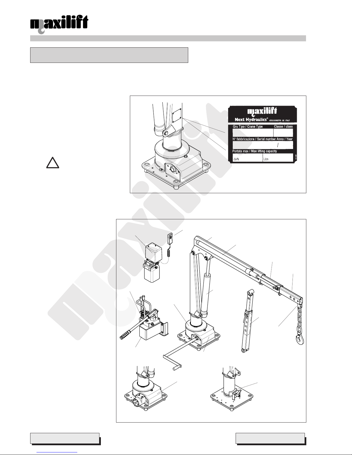
Every loader is identified by its serial number and name of the model written on the plate riveted on the column (Pict. 1).
3.1.1 Name plate description
¾ Crane model
¾ Serial number
¾ Y ear of manufacturing
¾ Lifting class
¾ Max SWL [kg]
¾ Max SWL [lbs]
A TTENTION
It is strictly forbidden to change and/
or erase the data written on the name
plate.
3.2 Main crane components identification
The main components of a telescopic
boom crane are (pict. 2):
¾ Slewing support
¾ Column
¾ Boom assembly
¾ Operating system
The full crane structure is positioned
and slews over the rotation support,
which is consequently the slewing
system housing.
The column is the slewing component
on which the most important
articulation fulcrums allowing boom
lifting are located. The boom can be
lifted in two ways:
¾ hydraulically, by means of a
lifting cylinder;
¾ manually, by keeping it in fixed
position by means of a
mechanical support strut.
The boom assembly is the element
allowing load recovering and hooking.
It is consisting of:
¾ boom, on which the articulation
fulcrums are located;
¾ extensions, allowing its in & out
movements (manual or hydraulic
by means of a cylinder);
¾ hook attachment.
Pict. 1
Pict. 2
Hook
attachment
Extension
cylinder
Boom
Motor pump
Button strip
Lifting
cylinder
1st extension
2nd extension
Mechanical
strut
Braking
device for
thrust
rotation
Slewing
support
Control valve
bank
Hand pump
Hydraulic
slewing
device
Crank
slewing
device
Via Mediterraneo, 6 - 42022 - Boretto - Reggio Emilia - Italy
Tel. +39 - 0522-96 30 0 8 - Fax +39 - 0522-96 30 39
info@maxiliftcrane.com
- 3 -
Finally , the operating system is the hydraulic or electro-hydraulic system transmitting the movement to the actuators
(cylinders). It is consisting of a pump (electric or manual) and control system (button strip or hydraulic valve bank).
In this type of crane the slewing support and column assembly make up the slewing system, which can be of three
types:
¾ thrust rotation;
¾ crank rotation (operating a worm screw – worm wheel gear);
¾ hydraulic (hydraulic motor operating a worm screw – worm wheel gear).
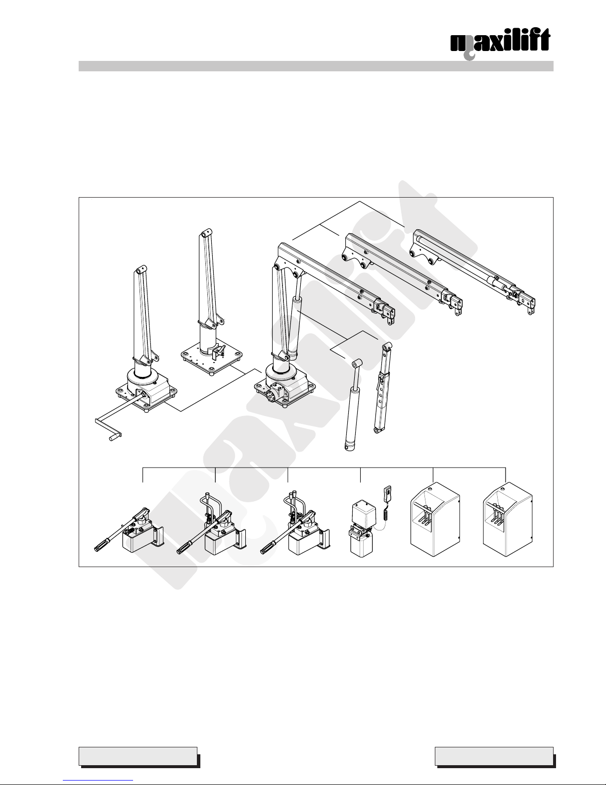
3.3 Crane composition
A1 Thrust slewing system (6.6.1)
A2 Crank slewing system (6.6.2)
A3 Hydraulic slewing system (6.6.3)
B1 Boom lifting system by mechanical strut (6.6.4)
B2 Boom lifting system by hydraulic cylinder (6.6.5)
C1 Two manual extensions boom system (6.6.6)
C2 Boom system with 1st hydraulic and 2nd manual extensions (6.6.7)
D1 Hydraulic operating system with hand pump for lifting cylinder (6.6.8)
D2 Hydraulic operating system with hand pump for lifting and extension cylinders (6.6.9)
D3 Hydraulic operating system with hand pump for extension cylinder (6.6.10)
D4 Electro-hydraulic operating system by power unit with single function for lifting cylinder (6.6.1 1)
D5 Electro-hydraulic operating system by power unit with two functions for lifting and extension cylinders (6.6.12) or
for slewing and lifting cylinder (6.6.13)
D6 Electro-hydraulic operating system by power unit with three functions for slewing, lifting and extension cylinders
(6.6.14)
Pict. 3
A2
Lifting
Boom system
Slewing system
Operating system
A1
C2
C1
B1
B2
D1 D2 D3 D4 D5 D6
A3
Via Mediterraneo, 6 - 42022 - Boretto - Reggio Emilia - Italy
Tel. +39 - 0522-96 30 08 - Fax +39 - 0522-96 30 39
info@maxiliftcrane.com
- 4 -
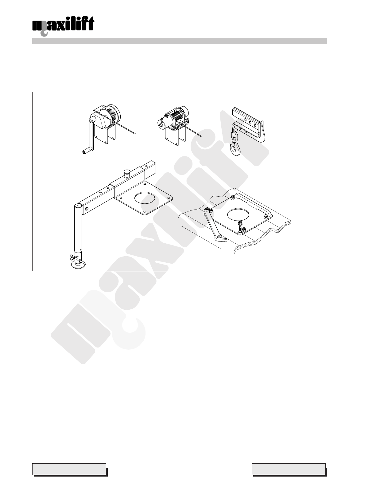
3.4 Accessories
According to crane use, there are accessories whose application is not compulsory , but which are essential in some
cases. These are:
¾ Winch (see chap. 6.7.1 for electrical winch and 6.7.2. for the manual winch);
¾ Stabilizers (see chap. 6.7.3).
The merely optional accessories are:
¾ Back load attachment (see chap. 6.7.4).
¾ Quick fitting kit (see chap. 6.7.5).
3.4.1 Winch
The winch is a rope lifting device, which is installed on the crane boom, through proper fastening, and which together
with the transmission, coupling and safety devices, becomes an integral part of it
The winch is an accessory allowing the vertical load handling.
On cranes equipped with mechanic strut, the winch is no longer an accessory , rather an essential component, as it is
the only available lifting device.
On this crane, the winch can be either mechanical or electrical, and relevant instructions are reported respectively in
sub-paragraphs 6.7.1 and 6.7.2.
3.4.2 Stabilizers
The stabilizers are installed on the vehicle to increase stability and prevent overturning.
The stabilizers are consisting of rods to whose end a stabilizer leg is applied; such leg is an extendable telescopic tube
which lowers and leans on the ground by a plate. Such rods can be either fixed or extendable from a tube fixed on the
vehicle, called main beam; the rod locking in this case is made by means of an automatic hooking device.
The stabilizer’s instructions for use are listed in sub-paragraph 6.7.3.
Pict. 4
Manual winch Electrical winch Back load attachment
Stabilizer Quick fitting
system

Via Mediterraneo, 6 - 42022 - Boretto - Reggio Emilia - Italy
Tel. +39 - 0522-96 30 0 8 - Fax +39 - 0522-96 30 39
info@maxiliftcrane.com
- 5 -
4 COMMISSIONING
4.1 Check list before the first commissioning
Check that the crane is complete of:
¾ CE declaration of conformity of the crane manufacturer;
¾ CE declaration of conformity of the crane installing workshop or self-certification of installation performed according
to Manufacturer’s installation instructions;
¾ Operator’s and maintenance manual;
¾ other testing certificates according to Safety Law in force.
4. 2 Daily check list
¾ Check the existence of oil leaks;
¾ Check the correct working of all crane safety devices (as indicated in relevant paragraph);
¾ Check oil level and fill up if necessary;
¾ Check the good conditions of hoses and piping;
¾ Check the good conditions of the rope.
4.3 CE Certification
Fill in the CE certification document with the required crane identification data.
5 GENERAL SAFETY RULES
5.1 Rules concerning persons
¾ Always wear the prescribed personal safety devices.
¾ Always wear approved accident-prevention clothing such as: protective helmets, anti-slip shoes, protective gloves,
reflective jackets, breathing apparatus and protective glasses. Consult your employer regarding current safety
regulations and accident-prevention equipment.
¾ Do not wear rings, wristwatches, jewellery , loose-fitting or hanging clothing such as ties, torn garment s, scarves,
unbuttoned jackets or unzipped overalls which could get caught up by parts in motion.
¾ Keep quickly and readily available on the truck a first-aid box and a fire extinguisher. The fire extinguisher must
always be kept charged and has to be used according to current regulations.
5.2 Rules concerning the crane
¾ The Manufacturer is not liable for accidents occurred when using the crane caused by non fulfilment from the
operator’s side of current rules, laws and regulations.
¾ The regular crane functioning is guaranteed within a temperature range between 0°C and +40°C. If temperature
drops under 0°C, it is essential to replace the oil in the whole circuit by a less viscous one, as indicated in the
suggested oil table.
¾ Carefully read the Operator’s and maintenance manual before commissioning, using, servicing or doing any thing
on the loader.
¾ Read and follow all safety instruction plates applied on the loader before starting up, using, servicing or doing any
thing on the loader.
¾ If the crane is provided with electrical devices, before operating the loader make sure that its voltage (12V) is same
as the vehicle one.
¾ Do not use controls and hoses as handholds: these parts move and cannot provide stable support.
¾ The operator’s control desk must always be kept clean from oil, grease, mud and snow to avoid accidents due to
slippery surfaces.
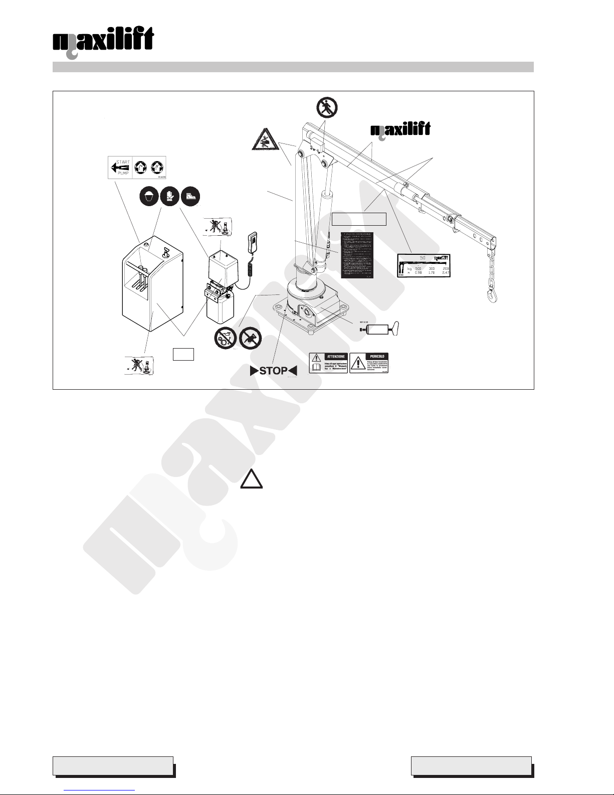
¾ The safety instruction plates, notices, load charts and any other sticker applied on the loader must be kept readable
and in good conditions. If necessary , replace them. The position of these plates is shown in pict. 5.
Via Mediterraneo, 6 - 42022 - Boretto - Reggio Emilia - Italy
Tel. +39 - 0522-96 30 08 - Fax +39 - 0522-96 30 39
info@maxiliftcrane.com
- 6 -
5.3 Rules concerning safety in the traffic
¾ The machine is an hydraulic loader for lorries and light trucks. The installation on the vehicle must be made in
compliance with the relevant national laws and regulations.
¾ When travelling on roads and public sites always respect the relevant national laws and regulations.
DANGER
Before travelling on roads, make sure that the loader is folded in rest position. If the loader is open or lying
on vehicle’s body exceeding the overall dimensions allowed by the highway code, it can hit bridges, electric
power lines or other obstructions.
¾ Before driving away, make sure that the levers and the pins securing the outrigger’s beam are fully locked. Accidental
slipping out of the outrigger beam during travelling can result in serious accidents.
¾ Special care must be taken when driving nearby crossroads, level-crossings and subways.
!
Pict. 5
1010
1010
10
1212
1212
12
22
22
2
11
11
1
66
66
6
44
44
4
55
55
5
33
33
3
88
88
8
99
99
9
MAX Kg200
1414
1414
14
1111
1111
11
12V
1212
1212
12
1313
1313
13
1515
1515
15
1616
1616
16
77
77
7

Via Mediterraneo, 6 - 42022 - Boretto - Reggio Emilia - Italy
Tel. +39 - 0522-96 30 0 8 - Fax +39 - 0522-96 30 39
info@maxiliftcrane.com
- 7 -
6 OPERATING INSTRUCTIONS
6. 1 Daily check list
¾ Check the existence of oil leaks;
¾ Check the correct working of the load limiting device, if installed (see on relevant paragraph);
¾ Check oil level and fill up if necessary;
¾ Check the good conditions of hoses and piping;
¾ Check the good conditions of the winch rope;
¾ Check the efficiency of thrust rotation brake
6.2 Loader classification and proper usage
The machine is an hydraulic truck loader for hook service. It can also be used for the same purpose from a static
mounting. The lifting capacity is 5 kNm, making it especially suitable for installation on light truck.
The crane is classified in class H1-B1 according to DIN 15018 standards, and must be used accordingly , that is: trucks
loading/unloading, hook service.
6.3 Improper usages
It is forbidden:
¾ T o use the loader in different operations from those it has been designed and built for . (see above point 6.2).
¾ To use the loader with attachment like: grabs, clamshells, magnets and so on.
¾ Pulling loads with loader in horizontal position.
¾ Crane operation with procedures not specified in this manual, or using components not foreseen during the design
phase.
¾ Non observance of the established maintenance programs.
¾ Non observance of safety rules.
¾ Perform interventions on the machine that imply the modification of components or parameters that influence the
working cycle.
¾ The unauthorized use of captive spare parts and components not specifically approved by the Manufacturer .
¾ T o carry out modifications or structural interventions without the approval of the Manufacturer .
¾ T o operate the loader out of the admissible range of temperatures.
Any of the above mentioned improper usages or non observance will cause:
¾ immediate cancellation of the Manufacturer Warranty .
¾ cancellation of Manufacturer liability for damage of people, animals, things.
A TTENTION
The improper usage can damage the loader and subsequently result in dangerous situations for the staff
entitled to its operation.
6.4 General attentions
DANGER
Before starting operations make sure that nobody is in the working area of the loader.
Preliminary prescriptions:
¾ The crane must work only if stabilized on flat and thick ground.
¾ Make sure that the truck is well braked and, if necessary , apply chocks to the tires.
If mechanical stabilizers are used:
¾ Pull the outrigger’s beams out of their housing till the yellow line painted on it is completely visible, and make sure
that the safety pins on the box are perfectly hooked on the beams.
¾ Lower the outriggers pads down to the ground. Be sure of not entirely lifting up the truck suspensions. It is important
for the truck stability that a part of the truck weight still burdens on the tires.
!

Via Mediterraneo, 6 - 42022 - Boretto - Reggio Emilia - Italy
Tel. +39 - 0522-96 30 08 - Fax +39 - 0522-96 30 39
info@maxiliftcrane.com
- 8 -
¾ Never operate the crane without having checked that the outriggers are well positioned on firm ground. If necessary ,
their bearing area must be increased with additional pads. The truck stability relies very much on the working
conditions! When the ground under the outrigger pads is sinking, their bearing area must be increased. The crane
Manufacturer can supply additional plates on request with increased area.
Before starting operations:
¾ Make sure that lifted loads do not exceed the allowed ones for every outreach.
¾ Make sure that the extension lock pins are correctly inserted and safely locked by their retainers (see pictures 9, 1 1,
12, 21, 25).
While operating:
¾ Lifting tackles, chains or ropes must be applied to the hook in such a way that will not damage the hook safety
latch.
¾ Avoid sudden movements especially during descent.
¾ Whilst swinging the boom always keep the load suspended from the ground. Dragging of the load is forbidden.
¾ Never stay or walk under hanging loads.
¾ Never start the loader operation without signalling it in a proper way .
¾ The load should never be lifted or carried on areas where people are passing or working. If this cannot be avoided in
any way , these operations must be properly signalled.
¾ Before leaving the controls, make sure that the control levers are in neutral position, and the load is resting on the
ground.
¾ When the working area of the crane cannot be clearly seen from the operator control deck, a second operator
charged with signalling is required.
General instructions:
¾ The stickers and plates applied on the loader are necessary to enable a safe usage of the same. Should them be
no longer readable, replace them as soon as possible by new ones.
¾ If the loader is accidentally hit, it has to be checked and tested from the closest authorized installer workshop.
¾ Check every month the state and correct functioning of all the parts subject to wear: pins, valves, hoses, sliding
pads and bushings, etc. If necessary replace by Original Sp are Parts.
¾ It is absolutely forbidden to tamper with the hydraulic circuit and open the safety seals. Failure to comply will cause
automatically the voiding of any warranty on the product. Valves adjustments or setting must be done only by
authorized installer workshops.
¾ It is absolutely forbidden to tamper with electrical parts, winches, lockpins and their housings.
¾ Carefully check conditions and wear of the rope and its couplings.
¾ Check the conditions of the hook and its safety latch.
Loader driven by DC power pack:
The DC power pack is connected with the truck battery . The electric pump will start, or will have to be started, each time
a lever of the control valve is moved. The loader can work for short periods even when the engine of the truck is off, but
it is strongly recommended to keep the engine idling, so the alternator can continuously charge the battery of the
vehicle.
DANGER
DC electric motor overheating. Keep the electric pump running for short periods to avoid its over heating.
The maximum working period of the pump depends on the pressure requested by the manoeuvres, but
should never exceed 5 minutes in any case, with intervals of 20 min. to enable a sufficient cooling.
A TTENTION
It is advisable to start the vehicle engine to avoid running down the battery when operating in a ventilated
area without any fire or explosion risks.
Stabilizing the truck:
¾ Bearing in mind the job to be done, the vehicle has to be positioned in the most convenient position, stopped with
the parking brake and the tires blocked.
¾ The truck engine shall be kept idling to allow batteries’ recharging.
¾ Extend the outriggers’ beams.
!
Via Mediterraneo, 6 - 42022 - Boretto - Reggio Emilia - Italy
Tel. +39 - 0522-96 30 0 8 - Fax +39 - 0522-96 30 39
info@maxiliftcrane.com
- 9 -
Always extend fully the outrigger beams to their working position (i.e.: maximum opening position), when foreseen, to
grant the maximum stability of the vehicle and safety .
A TTENTION
The outrigger beams are in their working position when the yellow band existing on every beam can be
entirely seen.
6.5 Ten basic rules for the safe loader operator
Always comply with the following ten basic rules:
¾ When approaching the crane for the first time, become on familiar terms with it, executing all the manoeuvres the
loader can perform during working.
¾ Carefully read all the prescriptions of this manual and execute step by step the activities hereby described to be
sure of the correct understanding.
¾ This manual must always be carried in the driver’s cab along with a copy of the load chart.
¾ Study and plan the best way to operate the crane: soil consistence, weight and dimensions of the loads to be lifted,
height to be raised and necessary booms outreach. Check available room or limitations due to the presence of
buildings, obstacles, electricity power lines, etc.
¾ Make sure of availability of all the necessary equipment : accident-prevention clothing, additional bearing plates
with increased surface area, slings, hooks, ropes and chains of certified origin and in perfect conditions.
¾ Before starting loader operations check the efficiency of the safety control devices. Never use the loader if the
correct functioning of a device is not sure.
¾ Traffic and safety laws in force must be strictly observed both when travelling on road and when operating the loader .
¾ The warnings of these manual referred to special dangers are to be read and observed with special care.
¾ The safety during the loader service must be kept to the highest level carrying out a regular, constant and accurate
preventive maintenance.
¾ Repairs if necessary should never be delayed, and must be made by specialized, authorized people using only
genuine spare parts.
6.6 Instructions for use
The crane instructions for use are based on
the analysis of the different functioning units
that are combining each other according to
the versions.
The main units are:
¾ Thrust slewing system
¾ Crank slewing system
¾ Hydraulic slewing system
¾ Boom lifting system by mechanical strut
¾ Boom lifting system by hydraulic
cylinder
¾ Lifting system by electrical winch
¾ Lifting system by manual winch
¾ Two manual extension boom system
¾ Boom system with 1st hydraulic and 2
nd
manual extensions
¾ Hydraulic operating system by hand
pump for lifting cylinder
¾ Hydraulic operating system by hand
pump for extension cylinder
¾ Hydraulic operating system by hand pump for lifting and extension cylinders
¾ Electro-hydraulic operating system by power unit with single function for lifting cylinder
¾ Electro-hydraulic operating system by power unit with two functions for lifting and extension cylinders
¾ Electro-hydraulic operating system by power unit with two functions for slewing and lifting cylinder
¾ Electro-hydraulic operating system by power unit with three functions for slewing, lifting and extension cylinders
VERSION Paragraphs
M50.2M MSF VE (VM) 6.6.1 – 6.6.4 – 6.6.6 – 6.7.1/6.7.2
M50.2M MLF VE (VM) 6.6.2 - 6.6.4 – 6.6.6 – 6.7.1/6.7.2
M50.2H PSF VE (VM) 6.6.1 – 6.6.4 – 6.6.5 – 6.6.10 – 6.7.1/6.7.2
M50.2H PLF VE (VM) 6.6.2 – 6.6.4 – 6.6.5 – 6.6.10 – 6.7.1/6.7.2
M50.2M PSH 6.6.1 – 6.6.5 – 6.6.6 – 6.6.8
M50.2M PLH 6.6.2 – 6.6.5 – 6.6.6 – 6.6.8
M50.2M ESH 6.6.1 – 6.6.5 – 6.6.6 – 6.6.1 1
M50.2M ELH 6.6.2 – 6.6.5 – 6.6.6 – 6.6.1 1
M50.2H PSH 6.6.1 – 6.6.5 – 6.6.7 – 6.6.9
M50.2H PLH 6.6.2 – 6.6.5 – 6.6.7 – 6.6.9
M50.2H ELH 6.6.2 – 6.6.5 – 6.6.7 – 6.6.12
M50.2M ERH 6.6.3 – 6.6.5 – 6.6.7 – 6.6.13
M50.2H ERH 6.6.3 – 6.6.5 – 6.6.7 – 6.6.14
Find your own version in the following table.
The sub-paragraphs that must be compulsorily read for using the crane
are indicated beside of it.
Via Mediterraneo, 6 - 42022 - Boretto - Reggio Emilia - Italy
Tel. +39 - 0522-96 30 08 - Fax +39 - 0522-96 30 39
info@maxiliftcrane.com
- 10 -
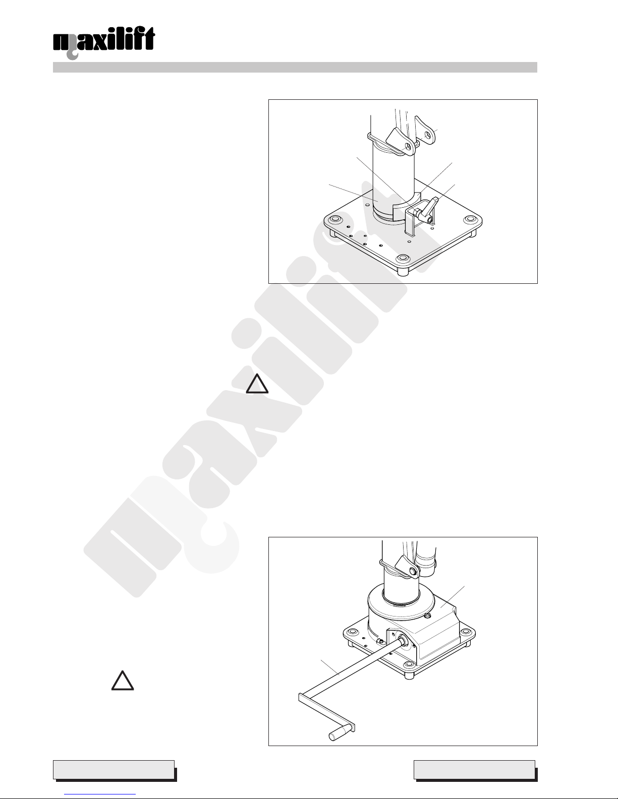
6.6.1 Thrust rotation system
Operation:
The thrust rotation system is so called because the
operator performs column rotation by pushing on
crane arm. The system is supported by a friction
braking device (pict. 6). It is consisting of a block
which is locked by a lever on a plastic ring fixed on
the slewing column.
Use:
¾ Before lifting a load, check braking system
efficiency by tightening the lever and trying to
push the boom without load.
¾ The operator has to push the crane boom in one
sense or the other to perform the slewing.
¾ After the slewing and before performing the
vertical load translation with the winch, or lifting by the cylinder , tighten further the brake lever to prevent any slewing
caused by load swinging or hunting.
After use:
¾ Shelter the crane in the min. overall volume position;
¾ Tighten the brake lever to lock the slewing, in order to prevent it from triggering spontaneously when the vehicle is
on the road due to the forces of inertia.
DANGERS
T o perform the thrust slewing, the brake lever must be tightened; the crane must rotate only if pushed by the
operator. Keep as far from the load as possible while it is being handled, always making sure that no p art of
the body is below of it, especially in case of load hunting. We advise against choosing this slewing system in
all situations where the crane base may be leaning compared with the horizontal line.
Do not lubricate or grease either the block or the plastic ring; this causes a braking reduction.
6.6.2 Crank rotation system
Operation:
This system is consisting of a worm screw/worm wheel gearing protected by a casing and driven by a crank (pict. 7).
Use:
To operate the system, it is necessary to:
¾ insert the crank in the proper housing made in
the worm screw;
¾ turn in either sense.
After use:
After the crane has been used, or before re-starting
off, pull out the crank and put it back in the lever
holder of the hand pump support.
If the crane is not provided with hand pump, put the
crank inside the boom assembly or in the tools
compartment.
DANGERS
Make sure that the slewing stop prevents
excessive traction stresses on the hydraulic
hoses .
Pict. 6
Pict. 7
!
!
Braking
block
lever
Ring
Screw
Casing
Crank
 Loading...