


LoRa Concentrator Card
GL5712 Datasheet
Version: LoRa Concentrator_GL5712_Datasheet_V1.0.0
Date: 2018-07-12
Maxiiot Ltd.
LoRa Concentrator Card_GL5712_Datasheet_V1.0.0
Document Revision Record
Version Date Description
V1.0.0 2018-07-12 Preliminary version Ming
Copyright Notice
All contents in the files are protected by copyright law, and all copyrights are reserved by Maxiiot Ltd. Without
written permission, all commercial use of the files from Maxiiot are forbidden, such as copy, distribute,reproduce
the files, etc., but non-commercial purpose, downloaded or printed by individual are welcome.
Disclaimer
Maxiiot Ltd reserves the right to change, modify or improve the document and product described herein . Its
contents are subject to change without notice. These instructions are intended for you use at your own risk .
Maxiiot Ltd www.maxiiot.com

Table of Contents
LoRa Concentrator Card_GL5712_Datasheet_V1.0.0
1. Description
1.1 Overview
1.2 Product features
1.3 Function block diagram
2. Pin definition
2.1 Pin assignment
2.2 Pin description
3. Specifications
3.1 General specifications
3.2 Electric specifications
3.3 Absolute maximum rating
3.4 Operating conditions
4. Typical hardware connections
..............................................................................................................................................................
...............................................................................................................................................................
....................................................................................................................................................
.........................................................................................................................................
..........................................................................................................................................................
......................................................................................................................................................
.......................................................................................................................................................
..........................................................................................................................................................
...........................................................................................................................................
............................................................................................................................................
.....................................................................................................................................
.............................................................................................................................................
...............................................................................................................................
1
1
1
2
3
3
3
5
5
5
6
6
8
4.1 Physical dimensions
4.2 Reference Circuit
4.3 Interfaces
4.3.1 Interface to host MCU
4.3.2 Power pins
4.3.3 RF connection
4.3.4 RESET pin
4.3.5 GPS_PPS
4.3.6 RF enable
5. Reliability test and approves
6. Package
7. Contact Us
...............................................................................................................................................................
..........................................................................................................................................................
............................................................................................................................................................
.............................................................................................................................................................
............................................................................................................................................................
.................................................................................................................................................................
.............................................................................................................................................................
..............................................................................................................................................
...................................................................................................................................................
........................................................................................................................................
.....................................................................................................................................................
...............................................................................................................................
8
8
9
9
9
9
9
9
9
10
10
10
Maxiiot Ltd www.maxiiot.com
LoRa Concentrator Card_GL5712_Datasheet_V1.0.0
1. Description
1.1
Overview
Automated Meter Reading
Home and Building Automation
Wireless Alarm and Security Systems
Industrial Monitoring and Control
Machine to Machine (M2M)
Internet of Things (IoT)
1.2 Product features
Multichannel: Eight(8) programmable Lora parallel demodulation channels.
SPI Interface:The SPI interface gives access to the configuration register of SX1301 via a synchronous
USB2.0 Interface: Build in FT232H chip convert SPI interface of SX1301 to USB2.0 .
Compact mini PCI express form factor TYP. 50.8*30.3*4.7mm (W*L*H)
Environmentally friendly RoHS compliant
Compliance:
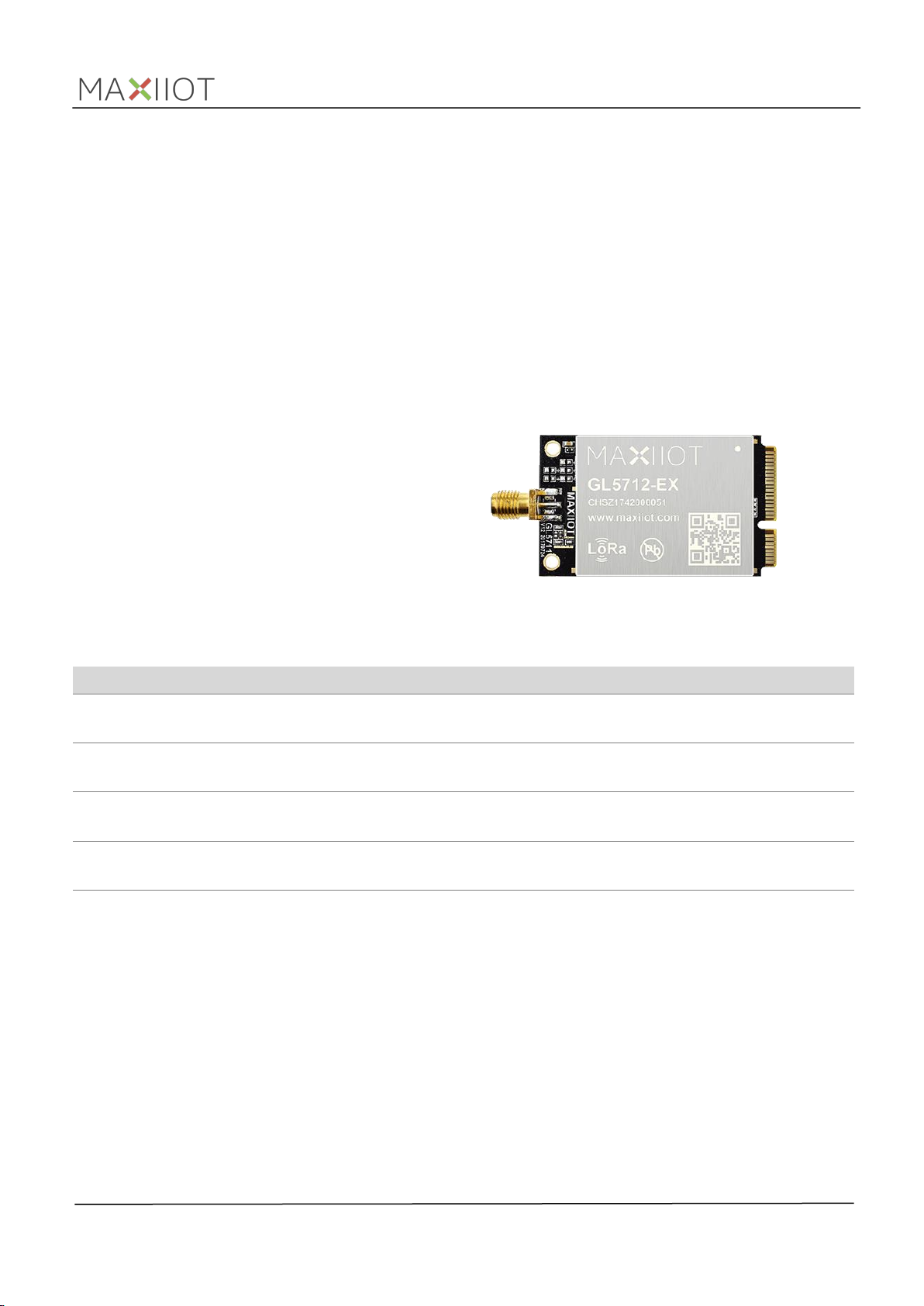
GL5712 is a LoRa concentrator card with industrial standard mini PCI express form factor based on SX1301
chipset and 2*SX1257 RF end-front . This mPCIe module can be used in any embedded platform offering a free
mPCIe slot with USB/SPI connectivity and capable of providing enough power for the module, enables
low-power wide area communication capabilities to your new gateway design or existing industrial
routers/computer.
Each module support eight(8) programmable Lora parallel demodulation channels, allowing it to receive up to
eight LoRa® modulated packets simultaneously. -142.5dBm high sensitivity combine with 17.5dBm power
amplifer yields industry leading link budget making it optimal for applications requiring extended range and
robustness.
Typical applications
GL5712 LoRa concentrator cards are available in four product variants
NO. Model Description Remark
1 GL5712-EX
2 GL5712-UX
3 GL5712-EA
4 GL5712-UA
Table1.1 Product variants
863~870MHz IPEX connector,is mainly designde for operation in Europe
and other countries.
902~928MHz IPEX connector,is mainly designed for operation in America
south-east Asia.
863~870MHz SMA connector,is mainly designde for operation in Europe
and other countries.
902~928MHz SMA connector,is mainly designed for operation in America
south-east Asia.
full-duplex protocol.
- US Version (GL5712-U): Certified to FCC Modular Transmitter Standards
- EU Version (GL5712-E): Certified to CE Modular Transmitter Standards
Maxiiot Ltd www.maxiiot.com
1
LoRa Concentrator Card_GL5712_Datasheet_V1.0.0
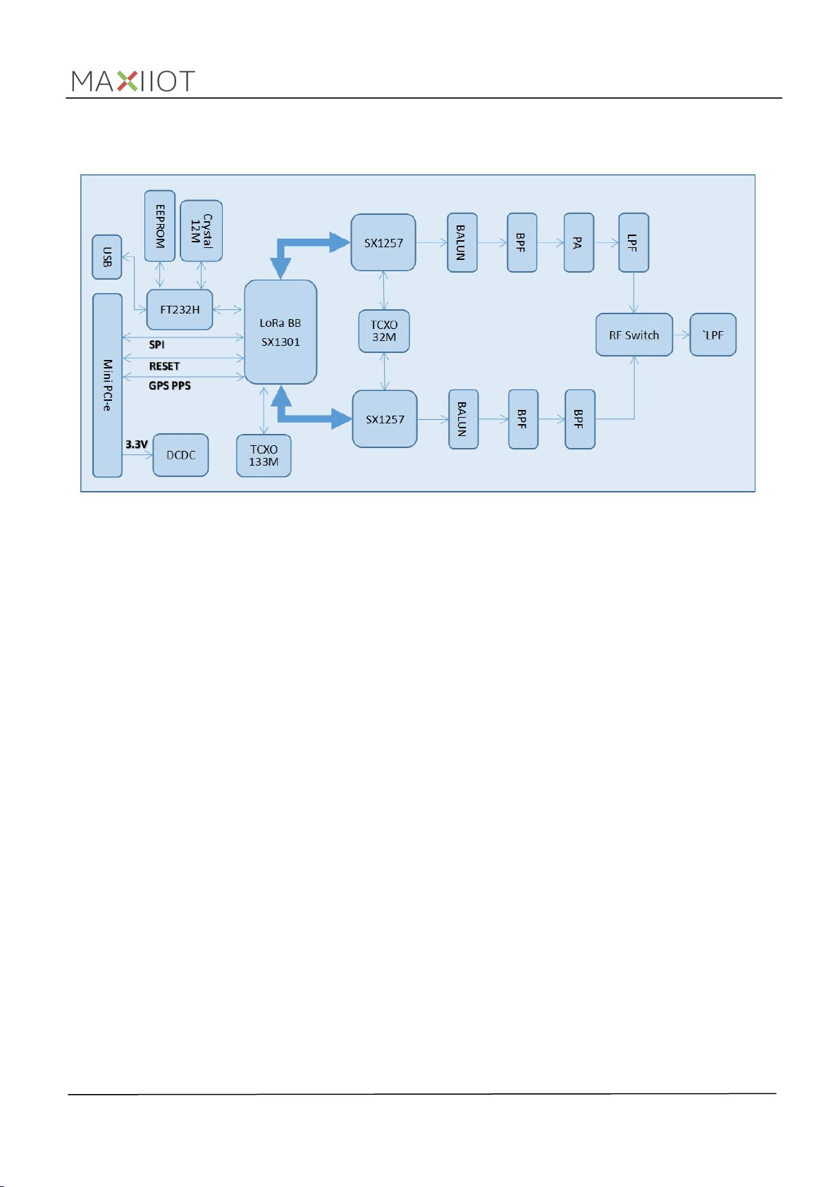
1.3 Function block diagram
Maxiiot Ltd www.maxiiot.com
2

LoRa Concentrator Card_GL5712_Datasheet_V1.0.0
2. Pin Definition
2.1 Pin assignment
2.2 Pin description
No. Symbol
1 NC N/A Not connected (Default)
2 +3.3V Supply input Supply voltage to the engine board.
3 NC N/A Not connected (Default)
4 GND GND Ground
5 NC N/A Not connected (Default)
6 NC N/A Not connected (Default)
7 NC N/A Not connected (Default)
8 NC N/A Not connected (Default)
9 GND GND Ground
10 NC N/A Not connected (Default)
11 NC N/A Not connected (Default)
12 NC N/A Not connected (Default)
13 NC N/A Not connected (Default)
14 NC N/A Not connected (Default)
15 GND GND Ground
Type Description
16 NC N/A Not connected (Default)
17 NC N/A Not connected (Default)
18 GND GND Ground
Maxiiot Ltd www.maxiiot.com
3

LoRa Concentrator Card_GL5712_Datasheet_V1.0.0
19 NC N/A Not connected (Default)
20 NC N/A Not connected (Default)
21 GND GND Ground
22 /Reset Reset input Reset Module, Active-low device Reset input
23 NC N/A Not connected (Default)
24 +3.3V Suupply input Main power supply to the engine board.
25 NC N/A Not connected (Default)
26 GND GND Ground
27 GND GND Ground
28 NC N/A Not connected (Default)
29 GND GND Ground
30 NC N/A Not connected (Default)
31 NC N/A Not connected (Default)
32 NC N/A Not connected (Default)
33 NC N/A Not connected (Default)
34 GND GND Ground
35 GND GND Ground
36 USB_DM USB Data Line D- USB Data Signal Minus
37 GND GND Ground
38 USB_DP USB Data Line D+ USB Data Signal Plus
39 +3.3V Supply inout Main power supply to the engine board.
40 GND GND Ground
41 +3.3V Supply inout Main power supply to the engine board.
42 NC N/A Not connected (Default)
43 GND GND Ground
44 NC N/A Not connected (Default)
45 SCK Host SPI interface SPI interface
46 GPS_IN GPS_IN GPS pps in
47 MISO Host SPI interface SPI interface
48 NC N/A Not connected
49 MOSI Host SPI interface SPI interface
50 GND N/A Ground
51 CSN Host SPI interface SPI interface
52 +3.3V Supply inout Main power supply to the engine board.
Table 2.1 Pin definition
Maxiiot Ltd www.maxiiot.com
4

3. Specifications
3.1 General specifications
Parameters Description
Modulation type
LoRa chipset SX1301
Multi-channel Eight (8) uplink , one (1) down link
Package Mini PCI express
Host interface USB/SPI
Frequency 863~870MHZ, 902~928MHZ(Opt.)
Receiving sensitivity -142.5dBm
ISM Band LoRa
®
LoRa Concentrator Card_GL5712_Datasheet_V1.0.0
Tx power dBm
Communication range 3~5KM in urban area , >15KM line-of-sight
Supply voltage +3.3V
Power consumption
Operating temperature
Operating humidity
Dimensions
ESD (Human Body Model) JEDEC JS-001 Standard±1kV, Class 2
Table3.1 General specification
17.5
Tx(Max)<700mA
Rx <200mA
-40~+85℃(industrial grade)
10%~90%, no-condensing
TYP. 50.8*30.3*4.5mm (W*L*H)
3.2 Electric specifications
ESD Notice: GL5712 is a high performance radio frequency device. It satisfies:
Class 2 of the JEDEC standard JESD22-A114 (Human Body Model) on all pins.
Class III of the JEDEC standard JESD22-C101 (Charged Device Model) on all pins
It should thus be handled with all the necessary ESD precautions to avoid any permanent damage.
The limiting values given are in accordance with the Absolute Maximum Rating System . Stress above
one or more of the limiting values may cause permanent damage to the device. These are stress ratings
only, and operation of the device at these or at any other conditions above those given in the
Characteristics sections of the specification is not implied. Exposure to these limits for extended
periods may affect device reliability.
Maxiiot Ltd www.maxiiot.com
5

LoRa Concentrator Card_GL5712_Datasheet_V1.0.0
3.3 Absolute maximum rating
3.4 Operating conditions
t
Symbol Description Condition
3.3Vaux
USB
SPDT_SEL Port select Input DC voltage at SPDT_SEL input pins –0.3 3.6
RESET MPCI reset input Input DC voltage at RESET input pin –0.3 3.6
SPI SPI interface Input DC voltage at SPI interface pin
GPS_PPS GPS 1 pps input Input DC voltage at GPS_PPS input pin –0.3 3.6
Rho_ANT Antenna ruggedness
Tstg Storage Temperature –40 85 °C
Table3.2 absolute maximum rating
Module supply
voltage
USB D+/D- pins Input DC voltage at USB interface pins 3.6
Input DC voltage at 3.3Vaux pins
Output RF load mismatch ruggedness a
ANT1
Min Max.
–
0.3 3.6
–
0.3 3.6
Stressing the device beyond the“Absolute Maximum Ratings”may cause permanent damage. The
product is not protected against over-voltage or reversed voltages. If necessary, voltage spikes
exceeding the power supply voltage specification, given in table above, must be limited to values within
the specified boundaries by using appropriate protection diodes.
10:1
Unit
V
V
V
V
V
V
VSWR
All specifications are at an ambient temperature of 25 ° C. Extreme operating temperatures can
significantly impact specification values. Applications operating near the temperature limits should be
tested to ensure the specification.
Parameter
Normal operating
temperature
Extended operating
temperature
Storage Temperature -40 +125 °C
Table3.3 operating temperature range
Operating beyond the specified operating conditions can affect device reliability.
Symbol Parameter Min. Typical
3.3Vaux
Table3.4 Operating power supply range
Min.
-20 +25 +65
-40 +85
operating supply voltage
Typ
Max.
Unit Remarks
fully functional and meet 3GPP specifications
°
C
RF performance may be affected by outside
°
C
normal operating range
3.00 3.30 3.60
Max.
Unit
V
Operating beyond the specified operating conditions can affect device reliability.
Maxiiot Ltd www.maxiiot.com
6
LoRa Concentrator Card_GL5712_Datasheet_V1.0.0
Item Parameter
Unit Condition
MIN TYP MAX
Transmit Frequency 863 870 MHz ISM Band(GL5712-E)
SPEC
Transmit Frequency
902
928 MHz ISM Band(GL5712-U)
TX
Transmit Power
+27
+30 dBm Including ANT Gain
Frequency Deviation 12.5 KHz 25 ℃
RX Receiving Sensitivity -142.5 dBm
Table3.5 RF receiver characteristics
GL5712 series LoRa RF characteristics are specified in the SX1257series Data Sheet .
Mode Condition Min Typ Max Unit
RF Idle All of the chip on the board enter idle mode or shutdown. 70 uA
Rx active TX disabled and shutdown PA. 120 185 mA
Tx active The power of TX channel is 17.5 dBm and 3.3V supply. 520 700 mA
Table3.6 Current consumption
Maxiiot Ltd www.maxiiot.com
7

LoRa Concentrator Card_GL5712_Datasheet_V1.0.0
4. Typical Hardware Connections
4.1 Physical dimensions
4.2 Reference Circuit
Item Length Width Thickness Unit Remark
Dimensions 50.8 30.3 4.7 mm
Table4.1 dimensions
Maxiiot Ltd www.maxiiot.com
8
LoRa Concentrator Card_GL5712_Datasheet_V1.0.0
4.3 Interfaces
4.3.1 Interface to host MCU
SPI interface
USB interface
4.3.2 Power pins
4.3.3 RF connection
4.3.4 RESET pin
4.3.5 GPS_PPS
4.3.6 RF enable
Reference circuit design shows the typical hardware connections for the module. Interfacing to the module
requires connecting to the signals provided on the GL5712 mPCIe connector as listed in pin description. Specific
interface connections are discussed in this chapter.
A SPI interface is provided on the PCIe_SCK, PCIe_MISO, PCIe_MOSI, PCIe_CSN pins of the system connector. The
SPI interface gives access to the configuration register of SX1301 via a synchronous full-duplex protocol. Only the
slave side is implemented.
GL5712 series modules support high speed USB interface with a built in TF232H chip convert SPI to USB, can be
connected to any USB host equipment with compatible drivers. The module can uses the USB signals through the
mPCIe interface.
GL5712 series modules has multiple power and ground pins available on the mPCIe connector.
It is recommended that all power and ground pins be used when connecting to the module.
GL5712 series modules have a U.FL connector for interfacing with an external antenna. For proper operation,
antenna selection must consider frequency band and impedance.
GL5712 series modules have an active-low reset input. Pulling this signal low during normal operation will cause
the module to execute a reset cycle.
GL5712 series modules include a GPS_PPS input used to receive time-stamped packets.
GL5712 series modules have an input signal used to enable the RF radio on the module. A low level on the
RF_ENABLE pin will disable all RF transmission and reception.
Maxiiot Ltd www.maxiiot.com
9
LoRa Concentrator Card_GL5712_Datasheet_V1.0.0
5. Reliability Test and Approves
6. Package
7. Contact Us
Tests for product family qualifications are according to ISO 16750 "Road vehicles–Environmental conditions and
testing for electrical and electronic equipment”, and appropriate standards.
Products marked with this lead-free symbol on the product label comply with the "Directive
2002/95/EC and Directive 2011/65/EU of the European Parliament and the Council on the
Restriction of Use of certain Hazardous Substances in Electrical and Electronic Equipment" (RoHS).
All Maxiiot GL5712 modules are RoHS compliant.
Compliance(Pending):
- US Version (GL5712-U): Certified to FCC Modular Transmitter Standards
- EU Version (GL5712-E): Certified to CE Modular Transmitter Standards
Module
Package
Form QTY Size
GL5712 Trays As required As required Undetermined
Table6.1 package
Maxiiot Ltd
Web: www.maxiiot.com
Tel:+86-755-2645-9429
Fax: +86-755-2947-6513
Office address : Room 302,3F, No. 16, Lane 1,Liuxian No.2 Road,Bao’an District.
518100 Shenzhen, China
Article number
Maxiiot Ltd www.maxiiot.com
10

Antenna Type:Cylindrical Antenna
Antenna Gain(Peak):5 dBi
Federal Communication Commission Statement (FCC, U.S.)
This equipment has been tested and found to comply with the limits for a Class B digital
device, pursuant to Part 15 of the FCC Rules. These limits are designed to provide
reasonable protection against harmful interference in a residential installation. This
equipment generates, uses and can radiate radio frequency energy and, if not installed
and used in accordance with the instructions, may cause harmful interference to radio
communications. However, there is no guarantee that interference will not occur in a
particular installation. If this equipment does cause harmful interference to radio or
television reception, which can be determined by turning the equipment off and on, the
user is encouraged to try to correct the interference by one of the following measures:
- Reorient or relocate the receiving antenna.
- Increase the separation between the equipment and receiver.
- Connect the equipment into an outlet on a circuit different from that to which the
receiver is connected.
- Consult the dealer or an experienced radio/TV technician for help.
This device complies with Part 15 of the FCC Rules. Operation is subject to the following
two conditions: (1) This device may not cause harmful interference, and (2) this device
must accept any interference received, including interference that may cause undesired
operation.
FCC Caution:
Any changes or modifications not expressly approved by the party responsible for
compliance could void the user's authority to operate this equipment.
IMPORTANT NOTES
Co-location warning:
This transmitter must not be co-located or operating in conjunction with any other
antenna or transmitter.
OEM integration instructions:
This device is intended only for OEM integrators under the following conditions:
The transmitter module may not be co-located with any other transmitter or antenna. The
module shall be only used with the external antenna(s) that has been originally tested
and certified with this module.
As long as the conditions above are met, further transmitter test will not be required.
However, the OEM integrator is still responsible for testing their end-product for any
additional compliance requirements required with this module installed (for example,
digital device emissions, PC peripheral requirements, etc.).
Validity of using the module certification:
In the event that these conditions cannot be met (for example certain laptop
configurations or co-location with another transmitter), then the FCC authorization for this
module in combination with the host equipment is no longer considered valid and the
FCC ID of the module cannot be used on the final product. In these circumstances, the
OEM integrator will be responsible for re-evaluating the end product (including the
transmitter) and obtaining a separate FCC authorization.
End product labeling:
The final end product must be labeled in a visible area with the following: “Contains
Transmitter Module
FCC ID: 2ARPP-GL5712UX

Information that must be placed in the end user manual:
The OEM integrator has to be aware not to provide information to the end user regarding
how to install or remove this RF module in the user's manual of the end product which
integrates this module. The end user manual shall include all required regulatory
information/warning as show in this manual.
FCC Radiation Exposure Statement:
FCC Radiation Exposure Statement:
FCC Radiation Exposure Statement:
FCC Radiation Exposure Statement:
FCC Radiation Exposure Statement:
This equipment complies with FCC radiation exposure limits set forth for an
This equipment complies with FCC radiation exposure limits set forth for an
This equipment complies with FCC radiation exposure limits set forth for an
This equipment complies with FCC radiation exposure limits set forth for an
This equipment complies with FCC radiation exposure limits set forth for an
uncontrolled environment. This equipment should be installed and operated
uncontrolled environment. This equipment should be installed and operated
uncontrolled environment. This equipment should be installed and operated
uncontrolled environment. This equipment should be installed and operated
uncontrolled environment. This equipment should be installed and operated
with minimum distance 20cm between the radiator & your body.
with minimum distance 20cm between the radiator & your body.
with minimum distance 20cm between the radiator & your body.
with minimum distance 20cm between the radiator & your body.
with minimum distance 20cm between the radiator & your body.
Antenna Type:Cylindrical Antenna
Antenna Gain(Peak):5 dBi
 Loading...