

MaxiiCopper Vi2304, Vi2308, Vi2316 Installation Manual
Vi2304 / Vi2308 / Vi2316 UTP Ethernet Extender’s Installation Manual
WARNING! - To reduce the risk of fire or electric shock, do not expose
this apparatus to rain or moisture. This apparatus shall not be exposed to
dripping or splashing and no objects filled with liquids, such as vases shall
be placed on the apparatus.
WARNING! - This apparatus is a Class I product. This product must
The MaxiiCopper Model Vi2304, Vi2308 and Vi2316 hubs are revolutionary
data transmission devices that extend full-duplex High-Speed Ethernet over
existing or new UTP infrastructures. They extend 10BaseT signals up to
3,000 ft. (909M), 100BaseT up to 2,100 ft. (640m) for 802.3 af and 800 ft.
(242m) for 802.3 at. They employ MaxiiCopper, an innovative and unique
Ethernet extension technology, that is designed to take full advantage of
high-bandwidth UTP cables and maintain a full-duplex 10 or 100 Mb/s
Ethernet connection up to the maximum range with minimum transmission
error and latency. Multiple remote network devices such as Mega-pixel IP
cameras or VoIP can be connected to a central LAN switching fabric with
ease. Their dual-rate capability provides an easy way to balance the best
possible network throughput and long-reach distance design. The Vi2304,
Vi2308 and Vi2316 support 4, 8 and 16 ports. 1 pair can be used for both
10BaseT and 100BaseT signals. 4 Pair is restricted to 100BaseT use.
These hubs need to be deployed along with Vi2301 on the remote end of
each UTP cable. They are equipped with LEDs to provide link status and
configured data rate for each port. They are completely transparent to the
corporate IP network and higher layer protocols and require no IP programming or other configurations.
The Vi2308 and Vi2316 are offered in 19 inch 1U height enclosure for
rack-mount or wall-mount applications. They are ideal for medium to large
scale IT networking or digital CCTV projects. The UTP cable needs to be
point to point without any branches.
Important Safety Warning
- Read and keep these instructions.
- Heed all warnings.
- Follow all instructions.
- Do not use this apparatus near water.
- Clean only with a dry cloth.
- Install in accordance with the manufacturer’s instructions.
- This installation should be made by a qualified service person and should conform to all local
codes.
- DO NOT bundle UTP or UTP signals in the same conduit as high-voltage wiring.
- To reduce the risk of fire or electrical shock, do not expose these products to rain, moisture,
dripping or splashing.
- No objects filled with liquids, such as vases, shall be placed on Vigitron equipment.
- DO NOT install the unit in a place where the operating ambient temperature exceeds 75°C.
- Make sure that the external power supply output voltage is in the recommended range.
- Do not install near any heat sources such as radiators, heat registers, stoves or other
apparatus (including DVRs and NVRs) that produce heat.
- Protect the power cord from being walked on or pinched particularly at power source,
convenience receptacles, and the point where they exit from the apparatus.
- Only use attachments/accessories specified by the manufacturer.
- Unplug this apparatus during lightning storms or when unused for long periods of time.
- Refer all servicing to qualified service personnel. Servicing is required when the apparatus
has been damaged in any way, such as when a power supply cord or plug is damaged, liquid
has been spilled, objects have fallen inside the apparatus, the apparatus has been exposed to
rain or moisture, does not operate normally, or has been dropped.
- The main plug is used as the disconnect device and shall remain readily operable.
CAUTION
RISK OF ELECTRIC SHOCK
DO NOT OPEN
CAUTION: TO REDUCE THE RISK OF ELECTRICAL SHOCK,
DO NOT REMOVE COVER. NO USER SERVICEABLE
PARTS INSIDE. REFER SERVICING TO QUALIFIED
SERVICE PERSONNEL.
be connected to a mains socket outlet thru an AC to DC Power supply.
WARNING! - The mains plug is used as the disconnect device and
shall remain readily operable.
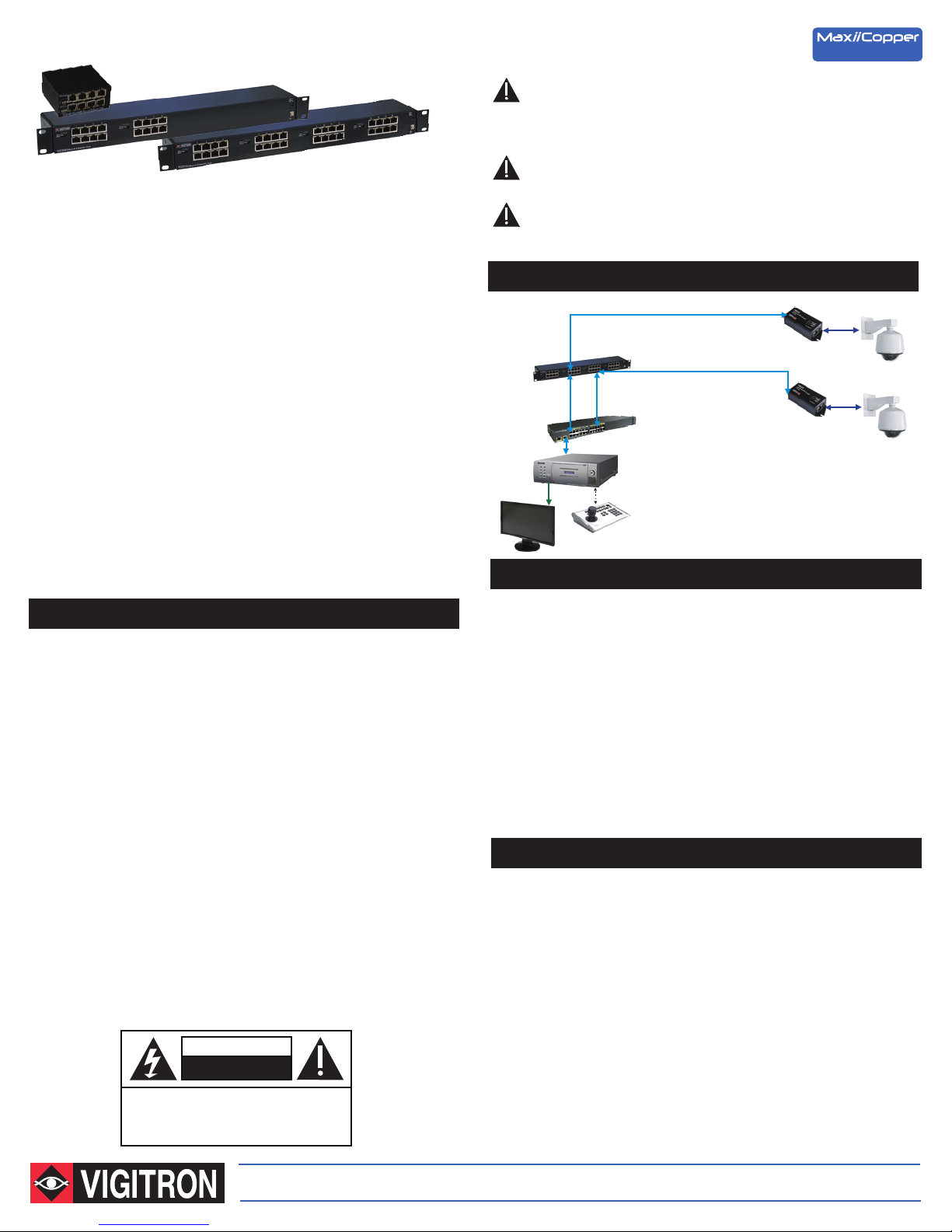
Application Drawing
Up to 3,000 ft./909 m UTP
Network Switch
Vi2316
Cat-5
(100 m)
NVR
Data
Up to 3,000 ft./909 m UTP
IP Camera-end Installation
- Use a Vi2301 single port extender for the camera side transmission.
- Set the Master/Slave dip switch of Vi2301 to “Master” mode.
- Set the 10/100 BaseT dip switch to the appropriate rate based on the
required maximum data rate and maximum distance.
- Connect the external 12VDC power supply to the power connector of the
Vi2301. An optional power adapter connector can be provided to simplify
connection. If no local power supply is present the Vi2301 will use POE.
- Connect the IP camera’s RJ45 connector to the 10/100BaseT Ethernet
port of Vi2301 using a standard Cat5/6 patch cable of maximum 330 feet
(100 m) in length.
- Connect one end of the long UTP cable to the RJ45 connector of Vi2301.
The link LED on the 10/100 connector should be “ON” to indicate proper
connection between the camera and Vi2301.
Ethernet Switch/NVR-end Installation
- Set the 10/100 BaseT dip switch of each port to match the setting on the
remote Vi2301 at the camera-end.
- Set the 1-pair/4-pair dip switch of each port to match the setting on the
remote Vi2301 at the camera-end.
- Connect the chassis ground screw to a solid earth ground.
- Connect the RJ45 connector of the Ethernet switch to the 10/100BaseT
Ethernet port of Vi2304/Vi2308/Vi2316 using a standard Cat5/6 cable
of maximum 100 m in length.
- Connect long UTP cables to the RJ45 connectors of the extender hub.
- Connect the 12V power supply to the power connector of the extender hub.
The link LED on the 10/100 Ethernet connectors should be “ON” to indicate
proper connection between the switch and Ethernet ports of
Vi2304/Vi2308/Vi2316. While the Link LED, Orange for 100BaseT and
Green for 10BaseT, on the extended side, in a steady state will indicate
confirmed connection between extenders.
Ethernet Extenders
Cat-5
Vi2301
IP Camera
Cat-5
Vi2301
IP Camera
The Smart Choice for Transmission Solutions www.vigitron.com
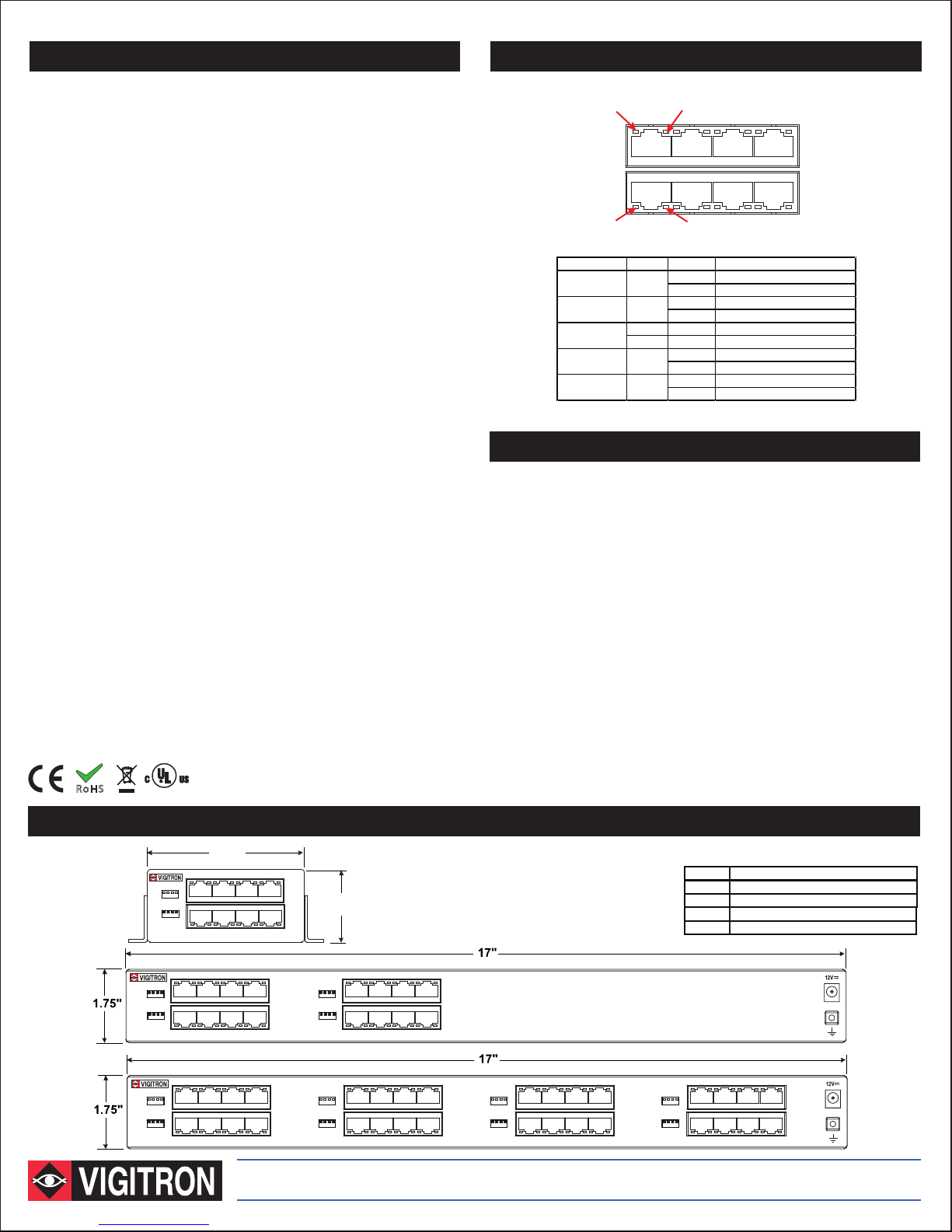
Technical Specifications*
LED Name Color Status Function
Connection is OK, 100BaseT Mode
Link
Traffic
10/100 BaseT
Traffic
Status LEDs
Electrical
Ethernet Interface Standard 10/100BaseT, Full duplex only
Ethernet Rate Dip Switch selectable 10/100 Mb/s
Full speed / full duplex at maximum rated distance
UTP** 100 Ohm, 3,000 ft (909 m) at 10BaseT 802.3 af
800 ft. (242m) at 100BaseT 802.3 at
Power Supply 12 VDC, 2.5 A
Status LEDs Extended Ethernet:Green/OrangeLED, 10/100BaseT
Yellow LED, Activity
Standard Ethernet: Green LED, Activity
Yellow LED, Link
Power On: Red LED
Connectors Ethernet Interface: RJ-45 Connector
Extended Interface: RJ-45 Connector
Power: IEC380-8 inlet
Environmental
Humidity 0 to 95%, non-condensing
Temperature Operating: -40°C to +75°C
Storage: -40°C to +80°C
Mechanical
Dimensions Vi2304: 1.15x3.6x3.3 in., 4.2x9.2x8.4 cm (HxWxL)
Vi2308: 1.75x3.25x17 in., 4.4x8.25x43 cm (HxWxL)
Vi2316: 1.75x3.25x17 in., 4.4x8.25x43 cm (HxWxL)
Weight Vi2304: 0.584 lb, 265 g
Vi2308: 1.8 lb (0.82 Kg)
Vi2316: 3.25 lb (1.5 Kg)
Material Aluminum
Accessories
12 VDC, 3 A wall-mount power supply (optional)
Rack mount brackets
*Specifications subject to change without notice.
**Distance figures are obtained using in house testing mirroring installations. Factors such as cabling, connections
use of power and environmental conditions may affect actual distances and should be taken into consideration.
RoHS
10/100BaseT
Activity
9 10 11 12
Extended Ethernet ports
Standard Ethernet ports
Activity
Power RED
(Extended Side)
(Extended Side)
(Standard Side)
(Standard Side)
YELLOW
ORANGE ON
GREEN
YELLOW
Link
OFF Power is OFF
ON Power is ON
OFF No Traffic
FLASHING Traffic
GREEN ON Connection is OK, 10BaseT Mode
OFF No connection
FLASHING Connection is OK with Traffic
OFF No connection
ON Connection is OK
Limited Lifetime Warranty
Vigitron, Inc. warrants that all Vigitron products (“Product”), if used in accordance
with these instructions, will be free of defects in material and workmanship for
lifetime defined as the duration period of time until product end of life is announcement. After which Vigitron will continue to provide warranty services for a period of 3
years. Period covering valid warranty will be determined by proof of purchase in the
form of an invoice from an authorized Vigitron dealer.
Warranty will only be provided for as long as the original end user purchaser owns
the product. Warranty is not transferrable. At Vigitron's option, defective product will
be repaired, replaced or substituted with a product of equal value. This warranty
does not apply if, in the judgment of Vigitron, Inc., the Product fails due to damage
from shipment, handling, storage, accident, abuse or misuse, or if it has been used
or maintained not conforming to Product manual instructions, has been modified, or
serial number removed or defaced. Repair by anyone other than Vigitron, Inc. or an
approved agent will void this warranty. Vigitron, Inc. shall not under any circumstances be liable to any person for any incidental, indirect or consequential
damages, including damages resulting from use or malfunction of the product, loss
of profits or revenues or costs of replacement goods. The maximum liability of
Vigitron, Inc. under this warranty is limited to the original purchase price of the
Product only.
3.6"
9.2cm
1 2 3 4
1 2 3 4
10BaseT
100BaseT
1 2 3 4
10BaseT
100BaseT
Vi2304 Ethernet Extender Hub
1 2 3 4
1 2 3 4
4-Pair
1-Pair
1 2 3 4
10BaseT
100BaseT
Vi2308 Ethernet Extender Hub
1 2 3 4
1 2 3 4
4-Pair
1-Pair
1 2 3 4
10BaseT
100BaseT
Vi2316 Ethernet Extender Hub
TEL (+1) 858 - 484 - 5209 • FAX (+1) 858 - 484 - 1205
10BaseT
100BaseT
10BaseT
100BaseT
4-Pair
1-Pair
4-Pair
1-Pair
7810 Trade Street, Suite 100, San Diego, CA 92121, USA • support@vigitron.com • www.vigitron.com
1.6"
4.2cm
5
6 7 8
5
6 7 8
5
6 7 8
5
6 7 8
5 6 7 8
5 6 7 8
Drawings
9 10 11 12
4-Pair
1-Pair
9 10 11 12
10BaseT
100BaseT
9 10 11 12
Ordering Information
PART No.
Vi2301
Single port UTP Ethernet Extender
Vi2304
4-port UTP Ethernet Extender
Vi2308 8-port UTP Ethernet Extender, 19”, 1U
Vi2316 16-port UTP Ethernet Extender,
Vi0014 12VDC, 3A Wall-mount Power Supply
13 14 15 16
16
13
15
14
4-Pair
1-Pair
16
13
15
14
10BaseT
100BaseT
Description
© Copyright 2013 Vigitron, Inc.
Vi2316_Instruction Manual
19”, 1U
 Loading...