

MaxiiCopper Vi2300W Installation Manual
Vi2300W Ethernet Extender over UTP Installation Manual
Ethernet Extenders
The MaxiiCopper Model Vi2300W is a revolutionary data transmission
device that extends full-duplex high-speed Ethernet over existing UTP
infrastructures. It extends 10BaseT signals up to 3,000 feet (914m) and
100BaseT up to 2,100 feet (640m). It employs MaxiiCopper innovative
and unique Ethernet extension technology that is designed to take full
advantage of high-bandwidth networking cables and maintain a full-duplex
of 10 or 100 Mb/s Ethernet connection up to the maximum range with
minimum transmission error and latency.
The Vi2300W can connect multiple remote network devices, such as
Mega-pixel IP cameras or VoIP to a central LAN switching fabric with ease.
Its dual-rate capability feature provides an easy way to balance the best
possible network throughput and long-reach distance design. The Vi2300W
is a transceiver device that needs to be deployed on the camera side. It can
be used in conjunction with a Vi2301A or Vi25xx Extended Midspan. No IP
setting or configurations are required and it is completely transparent to the
corporate IP network and higher layer protocols. The UTP cable needs to be
point to point without any branches. Multiple segments can be joined
together using UTP couplers.
Important Safety Warning
- Read these instructions.
- Keep these instructions.
- Follow all instructions.
- Heed all warnings.
- Do not use this apparatus near water.
- Clean only with a dry cloth.
- Install in accordance with the manufacturer’s instructions.
- This installation should be made by a qualified service person and should
conform to all local codes.
- DO NOT bundle UTP or Coax signals in the same conduit as high-voltage
wiring.
- To reduce the risk of fire or electrical shock, do not expose these products
to rain, moisture, dripping or splashing.
- No objects filled with liquids, such as vases, shall be placed on Vigitron
equipment.
- DO NOT install the unit in a place where the operating ambient tempera
ture exceeds 75° C.
- Make sure that the external power supply output voltage is in the recom
mended range.
- Do not install near any heat sources such as radiators, heat registers,
stoves or other apparatus (including DVRs) that produce heat.
- Protect the power cord from being walked on or pinched particularly at
plugs, convenience receptacles, and the point where they exit from the
apparatus.
- Only use attachments/accessories specified by the manufacturer.
- Unplug this apparatus during lightning storms or when unused for long
periods of time.
- Refer all servicing to qualified service personnel. Servicing is required
when the apparatus has been damaged in any way, such as a power
supply cord or plug is damaged, liquid has been spilled, or objects have
fallen into the apparatus, the apparatus has been exposed to rain or
moisture, does not operate normally, or has been dropped.
- The mains plug is used as the disconnect device and shall remain readily
operable.
WARNING! - To assure proper performance, check all gaskets to
eliminate any spacing where water can penetrate.
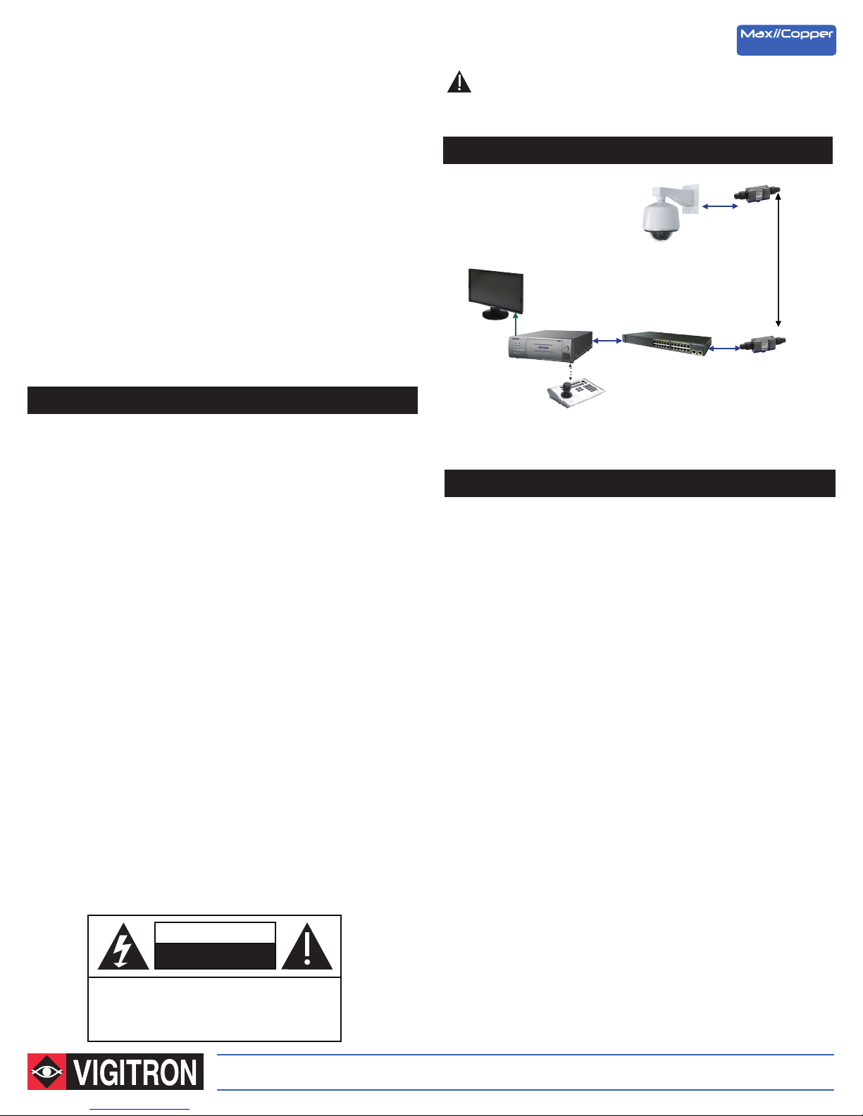
Application Drawing
Cat-5
Vi2300W
IP Camera
(914 m) UTP
Up to 3,000 ft.
Cat-5
NVR
Data
Network Switch
Vi2300W
IP Camera-end Installation
- When using PoE, the camera has to be powered by PoE also.
- Connect the IP camera RJ45 connector to the “Standard Ethernet” port
of Vi2300W using a standard Cat5/6 cable of maximum 100 m in length.
- Connect one end of the long UTP cable to the “Extended Ethernet” RJ45
connector of Vi2300W.
Unscrew the gasket and insert the UTP cable checking to confirm there is no
spacing between the wire and the insertion hole.
Connect the RJ45 cable and insert it into the RJ45 female connector on the
Vi2300A's body making certain the connection is tight.
Reconnect the gasket by screwing into the Vi2300W body making certain to
limit any wire slack.
CAUTION
RISK OF ELECTRIC SHOCK
DO NOT OPEN
CAUTION: TO REDUCE THE RISK OF ELECTRICAL SHOCK,
DO NOT REMOVE COVER. NO USER SERVICEABLE
PARTS INSIDE. REFER SERVICING TO QUALIFIED
SERVICE PERSONNEL.
The Smart Choice for Transmission Solutions www.vigitron.com

Ethernet Switch/NVR-end Installation
Limited Lifetime Warranty
- When using PoE, the camera has to be powered by PoE also.
- Connect the RJ45 connector of the Ethernet switch to the “Standard
Ethernet” port of Vi2301A using a standard Cat5/6 cable of maximum
328 feet (100 m) in length.
- Connect one end of the long UTP cable to the “Extended Ethernet” RJ45
connector of Vi2301A.
Unscrew the gasket and insert the UTP cable checking to confirm there is no
spacing between the wire and the insertion hole.
Connect the RJ45 cable and insert it into the RJ45 female connector on the
Vi2300A's body making certain the connection is tight.
Reconnect the gasket by screwing into the Vi2300W body making certain to
limit any wire slack.
Technical Specifications*
Vigitron, Inc. warrants that all Vigitron products (“Product”), if used in accordance
with these instructions, will be free of defects in material and workmanship for
lifetime defined as the duration period of time until product end of life is announcement. After which Vigitron will continue to provide warranty services for a period of 3
years. Period covering valid warranty will be determined by proof of purchase in the
form of an invoice from an authorized Vigitron dealer.
Warranty will only be provided for as long as the original end user purchaser owns
the product. Warranty is not transferrable. At Vigitron's option, defective product will
be repaired, replaced or substituted with a product of equal value. This warranty
does not apply if, in the judgment of Vigitron, Inc., the Product fails due to damage
from shipment, handling, storage, accident, abuse or misuse, or if it has been used
or maintained not conforming to Product manual instructions, has been modified, or
serial number removed or defaced. Repair by anyone other than Vigitron, Inc. or an
approved agent will void this warranty. Vigitron, Inc. shall not under any circumstances be liable to any person for any incidental, indirect or consequential
damages, including damages resulting from use or malfunction of the product, loss
of profits or revenues or costs of replacement goods. The maximum liability of
Vigitron, Inc. under this warranty is limited to the original purchase price of the
Product only.
Electrical
Ethernet Interface Standard 10/100BaseT
Ethernet Rate Auto selectable 10/100 Mb/s
UTP** 100 Ohm, 3000 feet (914 m) at 10BaseT
2,100 feet (640 m) at 100BaseT
Connectors Ethernet Interface RJ-45 Connector
Extended Interface RJ-45 Connector
Environmental
Humidity 0 to 95%, non-condensing
Temperature Operating: -40°C to +75°C
Storage: -40°C to +80°C
IP Rating Conforms to IP67
Mechanical
Dimensions 1.82 x 1.7 x 7 in (HxWxL)
46.2 x 43.2 x 177.8 mm
Weight 0.49 lbs., 220 g
Material Plastic
*Specifications subject to change without notice.
**Distance figures are obtained using in house testing mirroring installations. Factors such as cabling, connections,
use of power and environmental conditions may affect actual distances and should be taken into consideration.
RoHS
TEL (+1) 858 - 484 - 5209 • FAX (+1) 858 - 484 - 1205
7810 Trade Street, Suite 100, San Diego, CA 92121, USA • support@vigitron.com • www.vigitron.com
© Copyright 2015 Vigitron, Inc.
Manual_Vi2300W
 Loading...