

MaxiCool MMD2-18HDI, MMD3-27HDI Installation Manual

Beforeusingyourairconditioner,pleaseread
thismanualcarefullyandkeepitforfuturereference.
INVERTERONE-TWO/ONE-THREE
/ONE-FOUR/ONE-FIVESPLIT-TYPE
ROOMAIRCONDITIONER
MODELMMD2-18HDI
:
MMD3-27HDI
Pleasereadthisinstallationmanualcompletely
beforeinstallingtheproduct.
Ifthepowercordisdamaged,replacementwork
shallbeperformedbyauthorisedpersonnelonly.
Installationworkmustbeperformedinaccordance
withthenationalwiringStandardsbyauthorised
personnelonly.
Contactanauthorisedservicetechnicianfor
repair,maintenanceorinstallationofthisunit.
CONTENTS
SAFETYPRECAUTIONS
Warning...........................................................................................................................................2
Caution............................................................................................................................................2
INSTALLATIONINSTRUCTIONS
Selectinginstallationplace...............................................................................................................3
Wall-mountedtype...........................................................................................................................3
Accessories.........................................................................................................4
Four-waycassettetype................................................................................................................9
Duct&Ceilingtype.......................................................................................................................12
CeilingandFloortype....................................................................................................................16
FloorandStandingtype(Console)..................................................................................................19
Outdoorunitinstallation................................................................................................................23
REFRIGERANTPIPECONNECTION
Refrigerantpipeconnection..........................................................................................................24
ELECTRICALWORK
Electricalwork.............................................................................................................................25
AIRPURGING
Airpurgingwithvacuumpump.....................................................................................................27
Safetyandleakagecheck............................................................................................................29
TESTRUNNING
Testrunning..................................................................................................................................30
ReadThisManual
Insideyouwillfindmanyhelpfulhintsonhowtoinstallandtesttheairconditionerproperly.
Alltheillustrationsandspecificationsinthemanualaresubjecttochangewithoutpriornoticeforproduct
improvement.Theactualshapeshouldprevail.
CAUTION
Contactanauthorisedservicetechnicianforrepairormaintenanceofthisunit.
Contactanauthorisedinstallerforinstallationofthisunit.
Theairconditionerisnotintendedforusebyyoungchildrenorinfirmedpersonswithoutsupervision.
Youngchildrenshouldbesupervisedtoensurethattheydonotplaywiththeairconditioner.
Ifthepowercordistobereplaced,replacementworkshallbeperformedbyauthorisedpersonnelonly.
InstallationworkmustbeperformedinaccordancewiththenationalwiringStandardsbyauthorised
personnelonly.
1
SAFETYPRECAUTIONS
ReadthefollowSAFETYPRECAUTIONScarefullybeforeinstallation.
Electricalworkmustbeinstalledbyalicensedelectrician.Besuretousethecorrectrating
ofthepowerplugandmaincircuitforthemodeltobeinstalled.
Incorrectinstallationduetoignoringoftheinstructionwillcauseharmordamage.
Theseriousnessisclassifiedbythefollowingindications.
WARNING
CAUTION
Thissymbolindicatesthepossibilityofdeathorseriousinjury.
Thissymbolindicatesthepossibilityofinjuryordamagetoproperty.
Theitemstobefollowedareclassifiedbythesymbols:
SymbolwithbackgroundwhitedenotesitemthatisPROHIBITEDfromdoing.
WARNING
1)Engagedealerorspecialistforinstallation.Ifinstallationdonebytheuserisdefective,itwillcausewater
leakage,electricalshockfire.
2)Installaccordingtothisinstallationinstructionsstrictly.Ifinstallationisdefective,itwillcausewater
leakage,electricalshockfire.
3)Usetheattachedaccessoriespartsandspecifiedpartsforinstallation.otherwise,itwillcausethesettofall,
waterleakage,electricalshockfire.
4)Installatastrongandfirmlocationwhichisabletowithstandthesetsweight.Ifthestrengthisnotenough
orinstallationisnotproperlydone,thesetwilldropandcauseinjury.
5)Forelectricalwork,followthelocalnationalwiringstandard,regulationandthisinstallationinstructions.An
independentcircuitandsingleoutletmustbeused.Ifelectricalcircuitcapacityisnotenoughordefectfound
inelectricalwork,itwillcauseelectricalshockfire.
6)Usethespecifiedcableandconnecttightlyandclampthecablesothatnoexternalforcewillbeactedon
theterminal.Ifconnectionorfixingisnotperfect,itwillcauseheat-uporfireattheconnection.
7)Wiringroutingmustbeproperlyarrangedsothatcontrolboardcoverisfixedproperly.Ifcontrolboardcover
isnotfixedperfectly,itwillcauseheat-upatconnectionpointofterminal,fireorelectricalshock.
,
8)Whencarryingoutpipingconnection,takecarenottoletairsubstancesotherthanthespecified
refrigerantgointorefrigerationcycle.Otherwise,itwillcauselowercapacity,abnormalhighpressure
intherefrigerationcycle,explosionandinjury.
9)Donotmodifythelengthofthepowersupplycordoruseofextensioncord,anddonotsharethe
singleoutletwithotherelectricalappliances.Otherwise,itwillcausefireorelectricalshock.
CAUTION
1)Thisequipmentmustbeearthedandinstalledwithearthleakagecurrentbreaker.Itmaycauseelectrical
shockifgroundingisnotperfect.
2)Donotinstalltheunitatplacewhereleakageofflammablegasmayoccur.Incasegasleaksand
accumulatesatsurroundingoftheunit,itmaycausefire.
3)Carryoutdrainagepipingasmentionedininstallationinstructions.Ifdrainageisnotperfect,water
mayentertheroomanddamagethefurniture.
2

INSTALLATIONINSTRUCTIONS
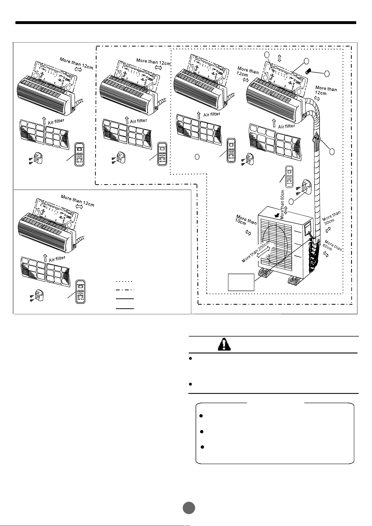
1.Wall-mountedtype
Selectinginstallationplace
Readcompletely,thenfollowstepbystep.
Indoorunit
Donotexposetheindoorunittoheatorsteam.
Selectaplacewheretherearenoobstacles
infrontoraroundtheunit.
Makesurethatcondensationdrainagecan
beconvenientlyroutedaway.
Donotinstallnearadoorway.
Ensurethatthespaceontheleftandright
oftheunitismorethan12cm.
Useastudfindertolocatestudstopreventunnecessarydamagetothewall.
Theindoorunitshouldbeinstalledonthewallataheightof2.0metresormorefromthefloor.
Theindoorunitshouldbeinstalledallowingaminimumclearanceof15cmfromtheceiling.
Anyvariationsinpipelengthwill/mayrequireadjustmenttorefrigerantcharge.
Thereshouldnotbeanydirectsunlight.Otherwise,thesunwillfadetheplasticcabinetand
affectitsappearance.Ifunavoidable,sunlightpreventionshouldbetakenintoconsideration.
Fig.1
Outdoorunit
Ifanawningisbuiltovertheoutdoorunitto
preventdirectsunlightorrainexposure,
makesurethatheatradiationfromthe
condenserisnotrestricted.
Ensurethattheclearancearoundtheback
oftheunitismorethan30cm
morethan30cm
havemorethan200cmofclearanceandthe
connectionside(rightside)shouldhavemore
than60cmofclearance.
Donotplaceanimalsandplantsinthepathoftheairinletoroutlet.
Taketheairconditionerweightintoaccountandselectaplacewherenoiseandvibration
willnotbeanissue.
Selectaplacesothatthewarmairandnoisefromtheairconditionerdonotdisturbneighbors.
.Thefrontoftheunitshould
andleftsideis
Fig.2
Rooftopinstallation:
Iftheoutdoorunitisinstalledonaroofstructure,besuretoleveltheunit.
Ensuretheroofstructureandanchoringmethodareadequatefortheunitlocation.
Consultlocalcodesregardingrooftopmounting.
Iftheoutdoorunitisinstalledonroofstructuresorexternalwalls,thismayresultin
excessivenoiseandvibration,andmayalsobeclassedasanonserviceableinstallation.
3
INSTALLATIONINSTRUCTIONS
Toolsneededforinstallation:
Levelgauge
Screwdriver
Electricdrill,Holecoredrill(65φ mm)
Flaringtoolset
Specifiedtorquewrenches:1.8kgf.m,4.2kgf.m,
5.5kgf.m,6.6kgf.m(differentdependingonmodelNo.)
Spanner(halfunion)
Hexagonalwrench(4mm)
Gas-leakdetector
Accessories
Vacuumpump
Gaugemanifold
Usersmanual
Thermometer
Multimeter
Pipecutter
Measuringtape
Number
1
2
3
4
5
6
7
8
9
NameofAccessories
InstallationPlate
PlasticExpansionSheath
Self-tappingScrewAST3.9X25
Connecting
pipe
Assembly
Liquidside
Gasside
6.35
9.53
12.7
Remotecontroller
Self-tappingScrewBST2.9X10
Remotecontrollerholder
Optional
parts
Seal(forcooling&heatingmodelsonly)
DrainJoint
(forcooling&heatingmodelsonly)
Qty/oneunit’
1
5-8
(dependingonmodels)
5-8
(dependingonmodels)
Partsyoumustpurchase
Consultthetechnician
forthepropersize.
1
2
1
1
1
10
11
Note:Excepttheabovepartsprovided,theotherpartsneededduringinstallationyoumust
purchase.
Transferconnector
(Pipesizedifferfromappliancetoappliance.
NOTE:
Tomeetdifferentpipesizerequirement,sometimes
thepipeconnectionsneedthetransferconnector
toinstallontheoutdoorunit.)
Magneticring
()
Packedwiththeindoorunit
1-4
(onsomemodels)
1
4
INSTALLATIONINSTRUCTIONS
2
Morethan15cm
1
3
Remote
controller
Remote
controller
Remote
controller
One-Two
One-Three
One-Four
One-Five
5
Remote
controller
A
Loopa
connective
cable
B
4
Remote
controller
6
Airout
C
Fig.3
CAUTIONS
Thisillustrationisforexplanationpurposesonly.
Theactualshapeofyouraircondtionermaybe
slightlydifferent.
Copperlinesmustbeinsulatedindependently
CAUTION
Useastudfindertolocatestudstoprevent
unnecessarydamagetothewall.
Aminimumpiperunof3metresisrequired
tominimisevibration&excessivenoise.
TwooftheA,BandCdirectionsshouldbe
freefromobstructions.
5
INSTALLATIONINSTRUCTIONS
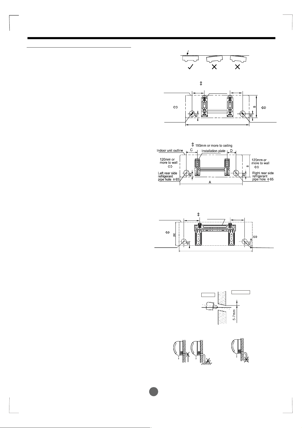
Indoorunitinstallation(wall-mountedtype)
1.FittheInstallationPlate
1.Fittheinstallationplatehorizontally
onstructuralpartsofthewallwith
spacesaroundtheinstallationplate.
2.Ifthewallismadeofbrick,concrete
orthelike,drilleight(8)5mmdiameter
holesinthewall.InsertClipanchorfor
appropriatemountingscrews.
3.Fittheinstallationplateonthewall
witheight(8)type “A” screws.
Note:
FittheInstallationPlateanddrill
holesinthewallaccordingtothe
wallstructureandcorresponding
mountingpointsontheinstallation
plate.TheInstallationPlatemaybe
slightlydifferentaccordingtothe
differentmodelsofindoorunit.
(Dimensionsarein “mm” unless
otherwisestated)
Correctorientation
ofInstallationPlate
Indoorunitoutline
120mmor
moretowall
Leftrearside
refrigerant
pipehole65
φ
ModelA(A:710,B:250,C:100,D:110)
ModelB()A:790,B:265,C:100,D:150
ModelA(A:710,B:250,C:100,D:110)
ModelB()A:790,B:275,C:100,D:85
ModelC()A:850,B:290,C:100,D:115
Fig.4
150mmormoretoceiling
C
Installationplate
A
D
120mmor
moretowall
Rightrearside
refrigerant
pipehole65
φ
2.Drillaholeinthewall
1.Determineholepositionsaccording
tothediagramdetailedinFig.5.Drill
one(1)hole(65mm)slantingslightly
φ
tooutdoorside.
2.Alwaysusewallholeconduitwhen
drillingmetalgrid,metalplateorthelike.
3.ConnectivePipeandDrainage
Installation
Drainage
1.Runthedrainhoseslopingdownward.
Donotinstallthedrainhoseas
illustratedinFig.7.
Indoorunitoutline
120mmor
moretowall
Leftrearside
refrigerant
pipehole65
φ
Donotblockwaterflowbyarise.
150
ModelA(A:920,B:293,C:150,D:185)
ModelB()A:995,B:293,C:150,D:200
ModelC()A:850,B:305,C:150,D:145
150mmormoretoceiling
Installationplate
918
Fig.5
Wall
Indoor
Fig.6
Donotputtheendof
drainhoseintowater.
190
Outdoor
120mmor
moretowall
Rightrearside
refrigerant
pipehole65
φ
Fig.7
6
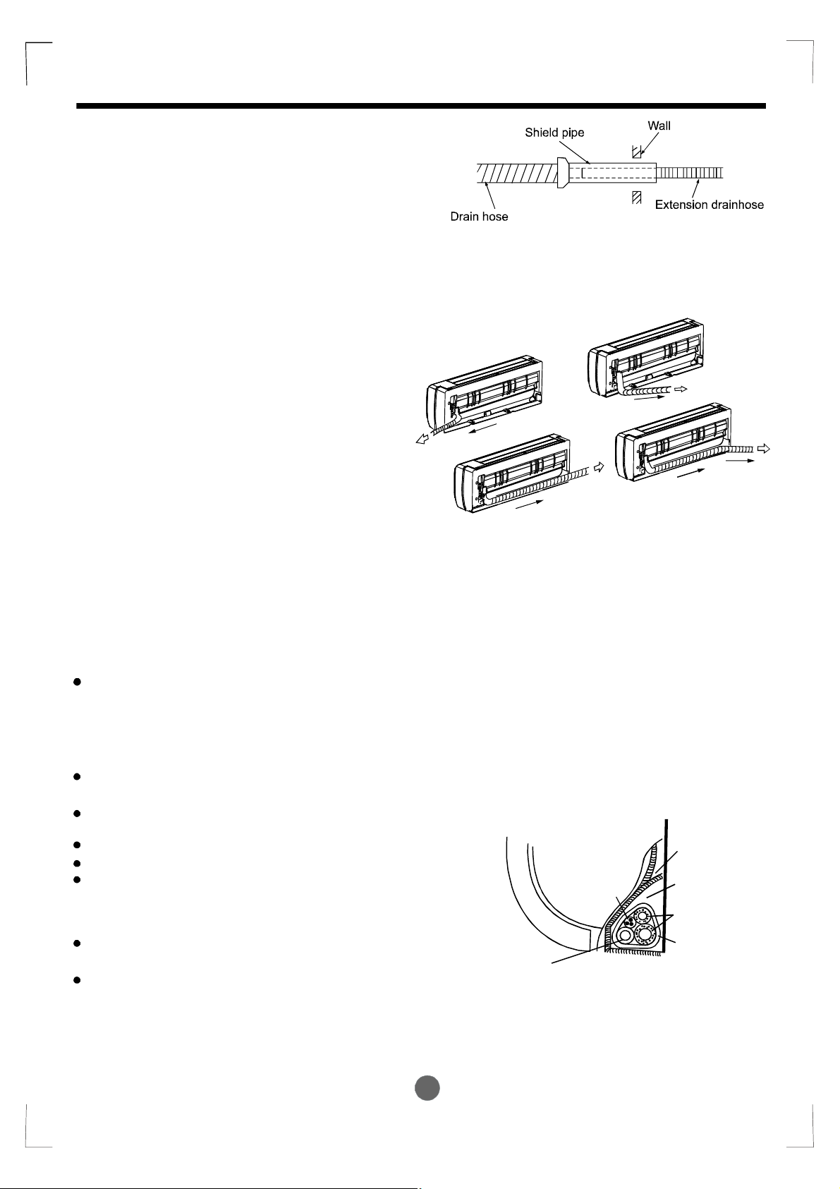
2.Whenconnectingextensiondrainhose,
insulatetheconnectingpartofextension
drainhosewithashieldpipe,donotlet
thedrainhoseslack.
INSTALLATIONINSTRUCTIONS
Connectivepipeinstallation
1.Fortheleft-handandright-handpiping,
removethepipecoverfromtheside
panel.
2.Fortherear-right-handandrear-left-hand
piping,installthepipingasshowninFig.10.
3.Fixtheendoftheconnectivepipe.(Refer
toTighteningConnectioninREFRIGERANT
PIPINGCONNECTION)
4.Pipingandwrapping
Bundlethetubing,connectingcable,anddrain
hosewithtapesecurely,evenlyasshownin
Fig.11.
Becausethecondensedwaterfromrearofthe
indoorunitisgatheredinpondingboxandis
pipedoutofroom.Donotputanythingelsein
thebox.
Right-handpiping
Left-handpiping
Fig.9
Fig.8
Rear-rightpiping
Rear-leftpiping
Fig.10
CAUTION
Connecttheindoorunitfirst,thenthe
outdoorunit.
Donotallowthepipingtoletoutfrom
thebackoftheindoorunit.
Becarefulnottoletthedrainhoseslack.
Heatinsulatedbothoftheauxiliarypiping.
Besurethatthedrainhoseislocatedat
thelowestsideofthebundle.Locating
attheuppersidecancausedrainpan
tooverflowinsidetheunit.
Neverintercrossnorintertwistthepower
wirewithanyotherwiring.
Runthedrainhoseslopeddownwardto
drainoutthecondensedwatersmoothly.
Indoorunit
Connective
cable
Drainhose
Pondingbox
Piperoom
Connective
pipe
Wrappingbelt
Fig.11
7

INSTALLATIONINSTRUCTIONS
4.Indoorunitinstallation
1.Passthepipingthroughtheholeinthe
wall.
2.Puttheupperclawatthebackofthe
indoorunitontheupperhookofthe
installationplate,movetheindoorunit
fromsidetosidetoseethatitissecurely
hooked(seeFig.12).
3.Pipingcaneasilybemadebyliftingthe
indoorunitwithacushioningmaterial
betweentheindoorunitandthewall.
Getitoutafterfinishpiping.
4.Pushthelowerpartoftheindoorunitup
onthewall,thenmovetheindoorunit
fromsidetoside,upanddowntocheck
ifitishookedsecurely.
10.5KW
Max.50m
7
(R410A)
(R410A)
(R407c/R22)
Max.10m
(R407c/R22)
Fig.12
Max.5m
8
INSTALLATIONINSTRUCTIONS
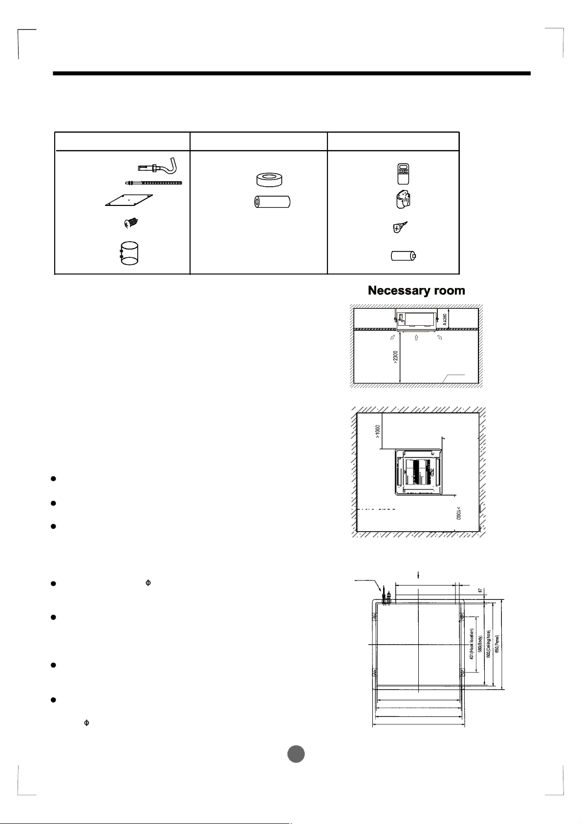
2.Four-waycassettetype
Attachedfittings
Pleasecheckwhetherthefollowingfittingsareoffullscope.Iftherearesomeattachedfittingsfree
fromuse,pleaserestorethemcarefully.
InstallationFittings
1.Expansiblehook.................................4
2.Installationhook.................................4
3.Installationpaperboard.....................1
Tubing&Fittings
6
.Connectingpipegroup.........................1
7.Bindingtape.........................................6
8.Soundproof/insulationsheath.............2
Remotecontroller&ItsFrame
(onsomemodels)
9.Remotecontroller...........................1
10.Frame.............................................1
4.BoltM612.....................4
M516or
×
5.Magneticring..........................................1
×
Notesbeforeinstallation
1.Decidethecorrectcarry-inpath.
2.Movethisunitasoriginallypackagedaspossible.
3.Iftheairconditionerisinstalledonametalpart
ofthebuilding,itmustbeelectricallyinsulated
accordingtotherelevantelectricalcode.
4.Ifinstallinginalonelybuildingoratahighposition
whereitishotandhumidwithfrequentthunderstorm,lightning-protectionequipmentisnecessary.
Indoorunitinstallation
1.Installthemainbody
A.Theexistingceiling(tobehorizontal)
a.Pleasecutaquadrangularholeof600600mm
×
intheceilingaccordingtotheshapeofthe
installationpaperboard.(RefertoFig.15&16)
Thecenteroftheholeshouldbeatthesame
positionofthatoftheairconditionerbody.
Determinethelengthsandoutletsoftheconnectingpipe,drainpipeandcables.
Tobalancetheceilingandtoavoidvibration,
pleaseenforcetheceilingwhennecessary.
b.Pleaseselectthepositionofinstallationhooks
accordingtothehookholesontheinstallation
board.
Drillfourholesof12mm,50~55mmdeepatthe
selectedpositionsontheceiling.Thenembed
theexpansiblehooks(fittings).
Facetheconcavesideoftheinstallationhooks
towardtheexpansiblehooks.Determinethe
lengthoftheinstallationhooksfromtheheight
ofceiling,thencutofftheunnecessarypart.
Iftheceilingisextremelyhigh,pleasedetermine
thelengthoftheinstallationhookaccordingto
facts.
Cuttheinstallationhookopeninthemiddle
position,thenuseapropriatelengthofreinforcing
rod(12)toweldtogether.
11.Mountingscrew(ST2.910-C-H)...2
12.Alkalinedrybatteries(AM4)............2
>1000
Drainside
×
Fig.13
Fig.14
A
422 28.5
580(Body)
600(Ceilinghole)
611(Hooklocation)
650(Panel)
Fig.15
OutletOutlet Inlet
Ground
>1000
9
 Loading...