

Maxford USA SPAD XIII Instruction Manual

SSPPA
Shown with optional detail upgrade package
Captain Eddie Rickenbacker
Jacques Raphaël Roques
Jacques Raphaël Roques
Shown with optional scale machine guns, engine and wooden propeller
Shown with optional scale machine guns, engine and wooden propeller
A
D
D
XIIIIII
X
G
G
S
AAS
G
//G
LLOOW
W
EPP
//E
11//55--SSCCAALLEE AARRFF RR//CC SSPPOORRTT--FFLLYYEERR VV11..11
IINNSSTTRRUUCCTTIIO
ONN
MAANNUUAALL
M
The SPAD XIII was a World War I French fighter developed by the Société Pour L'Aviation et ses Dérivés
(SPAD). Derived mainly from the earlier highly successful SPAD S.VII, its larger wings and rudder, more
powerful engine, and twin Vickers machine guns made it superior to its predecessors and one of the most capable
fighters of the war. The SPAD XIII was first flown on April 4, 1917; in May 1917 it was already being delivered
to the French Air Service.
Faster than its contemporaries, the British Sopwith Camel and the German Fokker D.VII, the SPAD XIII was
one of the most-produced fighters of WWI, with at least 8,472 built before the Arm istice, barely a year and a half
later on November 11, 1918.
Famous French pilots such as Georges Guynemer and Rene Fonck initially flew the SPAD XIII. Then, following the death of Quentin Roosevelt in a Nieuport 28, the Americans and other Allied forces also switched over to
fly the SPAD XIII. Among the Allied aces who flew the SPAD XIII were Eddie Rickenbacker (America's
leading ace with 26 victories – whose aircraft is on display at the National Museum of the U.S. Air Force near
Dayton, Ohio) and American ace Frank Luke (who had 18 confirmed victories, was the first airman to receive
the Medal of Honor, and in whose honor Luke Air Force Base is named). Francesco Baracca, Italy's top World
War I ace with 34 aerial victories was another high-scoring Allied pilot who flew a SPAD XIII.
This project to model the SPAD XIII was started in late 2009. We based our version on pilot Jacques Raphaël
Roques' SPAD XIII of the WWI French Air Service, SPA48, Aircraft Serial Number S1893.
This ARF is designed for a gas, glow, or electric power. Adjustable engine and motor mounting boxes are
included, and the model is close in scale to the actual SPAD XIII (though some necessary changes were made to
meet the needs and expectations of RC pilots as well as the requirements of factory-production).
We invite you to enjoy the pride of ownership and the joy of flying
this beautiful model of the famous SPAD XIII.
Page 1 of 16
S160205 / Copyright 2016
/
TABLE OF CONTENTS
Page 2 of 16
S160205 Copyri ght 2016
I. Safety Precautions & Assembly Tips .............. 2
II. Warranty, Liability Waiver & Return Policy .. 3
III. Specifications .................................................. 4
IV. Special features
................................................ 4
V. Parts List .............................................. 5
VI. Assembly Instructions .......................... 6
VII. Setup & Adjustments ......................... 16
VIII. Preflight Checks ................................. 16
I. SAFETY PRECAUTIONS & ASSEMBLY TIPS:
(IMPORTANT – READ THIS SECTION BEFORE YOU BEGIN ASSEMBLY)
1. This product should not be considered a toy, but rather a sophisticated, working model that
functions much like a full-scale airplane. Because of its performance capabilities, this product, if
not assembled and operated correctly, could cause injury to you or spectators and damage to
property. Maxford USA provides you with a high-quality, thoroughly tested model airplane kit with
assembly instructions. However, the quality and capabilities of your finished model airplane depend
on how you assemble it, and your safety depends on how you use and fly it. Any testing or flying of
this model airplane is done entirely at your own risk.
2. Assemble this model airplane according to these instructions. Do not alter or modify the model
beyond the assembly and power system options covered in these instructions, as doing so may
result in an unsafe or unworkable model. In a few cases the instructions may differ slightly from the
photos; in those instances the written instructions should be considered as correct. If you have any
question or concern about these instructions, before you proceed with assembly of this product,
contact your dealer, or speak to a Maxford USA customer service representative at 562-529-3988
(Monday through Friday, except national holidays, 9 AM to 5 PM Pacific time).
3. While this kit has been flight-tested to meet or exceed our rigid performance and reliability
standards in normal use, if you elect to perform any extremely high-stress flying, such as racing or
advanced aerobatics, or if you install a larger power system than specified, you (the buyer or user of
this product) are solely responsible for taking any and all necessary steps to reinforce the highstress points and/or substitute hardware that is more suitable for such increased stresses.
4. Throughout the lifetime of this model, use only the Maxford USA-recommended or same-sized
engine or motor and a new or well-maintained radio control system and batteries recommended by
the maker of your engine or motor and radio system.
5. It is your responsibility to install the R/C system and other components in such a way that this
model airplane passes all applicable safety/range tests and that the power system and controls
operate correctly and smoothly.
6. Recheck the operation of this model airplane before every flight to ensure that all equipment is still
operating correctly and that the model has remained structurally sound. Also before every flight,
check all electrical and/or structural connections; do not fly without replacing any that you find
damaged or worn.
7. Before you begin assembly of this model airplane, read all instructions and test-fit each part to
ensure you fully understand the instructions and that no parts are missing, damaged or unsatisfactory. (Note: Temperature and/or humidity differences and changes between the factory, our
warehouse and your home workshop may indicate the need for slight adjustment to the wing saddle
and/or the horizontal stabilizer’s mounting platform to ensure the wing is parallel to the horizontal
stabilizer; however, we recommend you contact us before you attempt any such adjustments.)
8. If you are not an experienced R/C pilot or have not flown this type of model
before, we strongly urge you to get assistance from an experienced R/C pilot.
9. To help ensure the security of the servo connections, we recommend you
install optional Maxford USA servo extension safety clips wherever servoleads are connected to any servo extender or Y-cable.
/
10. After you have determined each servo-mounting-screw location, apply thin CA adhesive to
Page 3 of 16
S160205 Copyri ght 2016
harden the wood where the servo’s mounting screws will be inserted.
11. Use the tip of a hot soldering iron to burn and remove any Mylar covering material that may
prevent you from obtaining good wood-to-wood gluing surfaces (such as at the bottom of the
horizontal stabilizer, between it and its mounting platform at the end of the fuselage).
12. Use 30-minute epoxy to permanently attach critical parts (such as where the horizontal stabilizer
is attached the to its mounting platform at the end of the fuselage).
13. If you have concern about the security of any factory fabrication procedure(s), we recommend
you apply 30-minute epoxy around the perimeter of such part(s) as an extra safety precaution.
14. A length of string may be supplied by the factory to pull your servo’s lead, servo extension, or
Y-cable through the airframe to your radio receiver; however, you might find it easier to use a
little masking tape to temporarily attach the connector to the end of a length of coat hanger wire,
then use the coat hanger wire to PUSH the lead and its connector through the airframe.
15. After you have adjusted each clevis into its position and secured it on its pushrod with the
supplied jam nut, we recommend you then also apply a drop or two of thin CA adhesive to make
this adjustment permanent. Also apply a thread-lock compound to secure your engine or motor
mounting hardware from vibration.
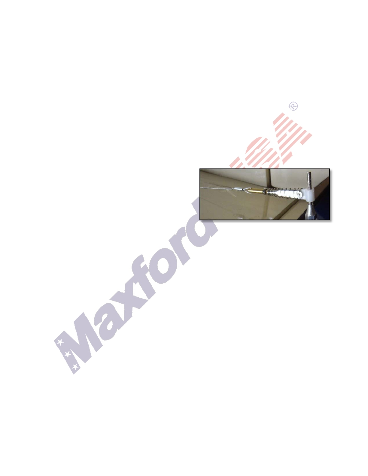
16. To use a crimp tube to attach one end of a pull-
pull cable to a brass rod and clevis …
a) Slide the crimp-tube onto the end of the cable.
b) Pass the end of the cable through the small
hole in the end of the brass rod.
c) Bring the end of the cable back into and all the
way through the crimp tube.
d) Loop the end of the cable back into the crimp tube, but this time leave the end of the cable
inside the crimp tube. (Using pliers, slide the cable inside the crimp tube to adjust the loops.)
e) Use your pliers to firmly squeeze several places along the length of the crimp tube to securely
crimp the tube onto the cable.
f) Snug the lock nut against the clevis to anchor the clevis to the brass rod.
g) Apply thin CA adhesive to permanently anchor both brass rods into their clevises.
17. This model includes some fiberglass and/or carbon-fiber reinforced parts. If you drill, grind or
sand a fiberglass or carbon-fiber reinforced part, never blow into the part to remove fiberglass or
carbon fiber dust (the dust may blow back into your face), and alwa ys wear safety goggles, a
particle mask and rubber gloves to guard yourself from eye, skin and respiratory-tract irritation.
18. Check the Mylar covering material’s joints and surfaces; if necessary, carefully use a dedicated
covering-material iron (do NOT set the iron’s temperature too high) to secure the edges and to
tighten any loosened areas. Recheck and retighten from time to time.
II. WARRANTY, LIABILITY WAIVER & RETURN POLICY:
Maxford USA guarantees this kit to be free from defects in material and workmanship at the time of
purchase. All our products have been inspected in our factory and are checked again when shipped
from our warehouse. However, Maxford USA cannot directly control the materials you may use nor
your final assembly process. Therefore
performance of your finished model airplane. Furthermore, in purchasing this product, you (the
buyer or user of this product) exempt, waive, and relieve Maxford USA from all current or future
liability for any personal injury, property damage, or wrongful death, and if you (the buyer or user
of this product) are involved in any claim or suit, you will not sue Maxford USA or any of its
representatives.
If you do not fully accept the above liability and waiver, you may request a return-merchandise
authorization number (RMA#) as explained in item 2 on the following page.
/
, Maxford USA can NOT in any way guarantee the

If you think there is a missing, damaged or unsatisfactory part, please read our after-sales service
Page 4 of 16
S160205 Copyri ght 2016
and return policy, below.
1. Inspect your order upon delivery for any missing, damaged or unsatisfactory part(s). If you
believe there is a problem, you must call us at 562-529-3988 (Monday through Friday except
holidays, between the hours of 9 AM and 5 PM Pacific time) before you begin assembly and
within 10 days from receipt of your purchase. During this telephone conversation, and with your
support, we will determine how to resolve your concern.
2. To request a return-merchandise authorization number (RMA#), call 562-529-3988 (Monday
through Friday except holidays, between the hours of 9 AM to 5 PM Pacific time). If we elect to
issue you an RMA#, you must clearly mark this RMA# on the outside of the package. (No return
or exchange will be authorized after 10 days from the date of your receipt of the product; any
package delivered to us without a Maxford USA RMA# is subject to being returned to the
sender, as received, with return postage payable upon delivery.) Returned merchandise must be
in its original condition as received from Maxford USA, with no assembly or modification, in the
product’s original packing materials, complete with all manuals and accessories. Return shipping
and insurance charges must be prepaid by you, the buyer.
3. Returned merchandise that is accepted by Maxford USA for credit is subject to a 10% to 20%
restocking fee (the final amount will be determined by Maxford USA upon receipt and
examination of the returned merchandise).
Return Address:
Maxford USA RC Model Distribution, Inc.
15939 Illinois Avenue, #C
Paramount, CA 90723
IMPORTANT: Print the RMA# issued by Maxford USA near the above address.
III. SPECIFICATIONS:
Wingspan ........................................................................................................................... 68-inches
Wing Area .......................................................... 885 sq. inches (combined, top and bottom wings)
Length .............................................................. 53-inches (includes prop on recommended engine)
ARF weight ...................................................................................................................... 10 pounds
Flying weight (complete with CRRC 26CC gas engine, batteries and radio system) ...... 13 pounds
Power System (not included) ......................... Gas – 26CC, Glow – 90-120, or Equivalent Electric
(plus batteries and switches corresponding to your Power and Radio Systems’ needs)
Propeller (not included) ................................................................................. 16 to 18 inch diameter
(as recommended by your power system’s manufacturer)
Radio system (not included) .................................. Minimum of 4 channels with 5 standard servos
(Hitec HS311 or equivalent, x5)
(Dimensions and weights are approximate.)
IV. SPECIAL FEATURES OF THIS ARF SPAD XIII:
• Realistic looking pre-trimmed windshield and pre-
painted scale-looking fiberglass cowl with wooden
louvers.
• The wings are easily removable in left and right pairs
for transport, storage, and in-field setup.
• Wing wires are included. (Since the wing wires are
not functional, wing wire installation is optional.)
/
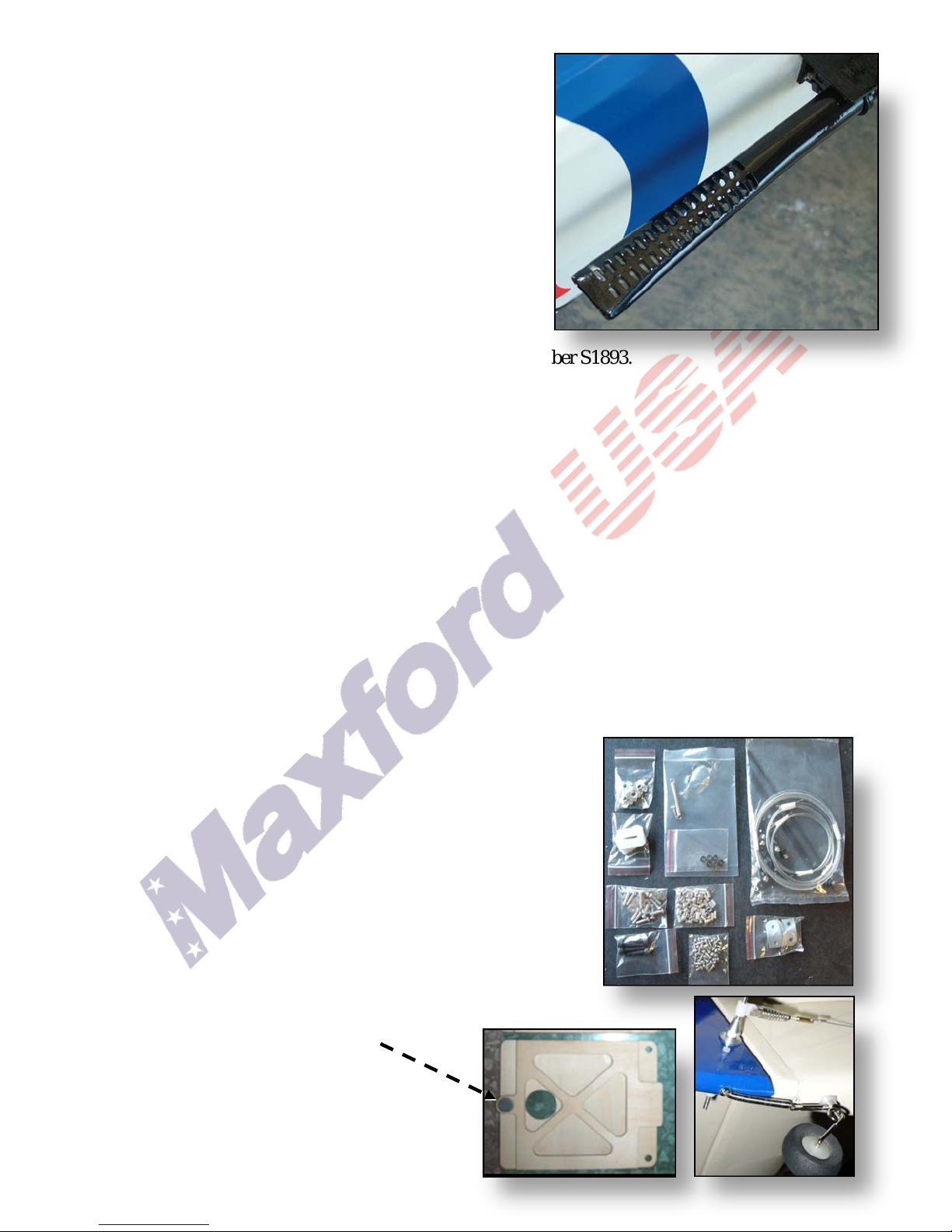
• True-to-scale twin exhaust pipes. (An optional upgrade
Page 5 of 16
S160205 / Copyright 2016
kit allows both exhaust pipes to be connected to a gasengine’s muffler.)
• The fuselage, wings and empennage are jig-
assembled, laser-cut balsa and light plywood,
finished with Mylar covering material; the rudder is
operated by pull-pull cables; a steerable tailwheel is
included.
• Includes a plywood box to securely mount and adjust
for the depth of most power systems, plus an
additional motor box for an electric power setup.
• The cockpit hatch is secured by a magnetic anchor.
• Includes scale markings for WWI French pilot
Jacques Raphaël Roques' SPAD XIII aircraft serial number S1893.
• Precut mounting slots inside the cockpit for radio and ignition power switches.
• Scale-looking landing gear and wheels.
• Available optional scale Vickers machine guns and matching 1/5-scale WWI pilot figure.
V. PARTS LIST:
1. Items you must supply
• Epoxy and cyanoacrylate (CA) adhesives, Micro Balloons or equivelant filler, masking tape, a
high-speed rotary tool, a soldering iron or wood burning tool and common hand tools (such as
screwdrivers, long-nosed and cutting pliers , et c.).
• Five(5) servos (see ‘Specifications’ on page 4), two 18-inch extender cables, one 12-inch
Y cable, and a four-channel (or more) radio control system.
• Gas, glow or electric power system and 16 to 18 inch diameter propeller.
• Any batteries and switches required for your ignition, electric power and/or radio system.
• Options: 1/5-scale Vickers machine guns; WWI pilot figure; and an exhaust manifold system for
connecting your gas engine’s muffler to the supplied twin exhaust pipes.
2. Included items
• • Rudder cables, aileron, elevator and throttle pushrods and all
related linkages; precut rudder, elevator and throttle servo
mounting trays.
Precut hinge slots; CA hinges, control horns, clevises and
pushrods, and all required hardware (except those items
normally supplied with servos, an engine or a motor).
•
Pre-trimmed, ready-to-install windshield, pre-painted fiberglass cowl, twin scale exhaust pipes, pre-covered fuselage,
wing panels, vertical and horizontal stabilizers, rudder and
elevator, and complete set of scale markings.
•
Wing rods, cabanes, struts, wing wire and wing-to-fuselage hardware.
•
Cockpit hatch with magnetic anchor.
•
Scale-looking landing gear.
•
Steerable tailwheel.
•
This illustrated Instruction Manual.
/
 Loading...