

Maxford USA PT-17 Instruction Manual

Entire contents – Copyright 2014
11//55 PPTT--1177 SSTTEEAARRM
Shown with optional upgraded scale dummy
engine, electric motor and propeller.
O
RRAADDIIO
IINNSSTTRRUUCCTTIIOON
CCOONNTTRROOLLLLEED
D
MMOODDEEL
N
MAANN AARRFF
L
MMAANNUUAAL
AAIIRRPPLLAANNEE
L
Congratulations on your acquisition of a Maxford USA ARF PT-17 Stearman!
The PT-17 is a biplane that was used as a military trainer by the US Army Air Corps during the 1930s and served throughout
WWII. The PT-17 is also widely known as the Stearman, Boeing Stearman, Boeing Model 75, or the Kaydet. At least 9,783 were
built and thousands of surplus PT-17s were sold on the civil market after the conflict.
This almost-ready-to-fly radio-control version of the PT-17 is based on the aircraft that is owned by John Mohr, who very
kindly sent us many detailed pictures of his personal aircraft. We also acknowledge and thank Jay Smith, editor or Model
Aviation, for his help and advice on this project.
This model is constructed mainly of laser-cut balsa and light plywood. As shown above, it is finished with a Mylar film
covering. It may also be special-ordered with a flat-finish Mylar or as a fabric-covered and prepainted ARF.
We invite you to enjoy the pride of ownership and the joy of flying your high-
quality balsa and light-ply almost-ready-to-fly version of this historic aircraft.
TABLE OF CONTENTS
I. Important safety precautions & assembly tips .... 2
II. Warranty, liability waiver, and return policy ..... 3
III. Special features of this Nieuport 28 model ........ 4
IV. Specifications ..................................................... 4
V. Parts List ............................................................. 4
VI. Assembly photo-instructions .......................... 5
VII. Setup and adjustments .................................. 17
VIII. Preparation for transport and field setup ...... 17
IX. Preflight checks ............................................ 18
Page 1 of 18 Copyright 2015 – PT17 / S150209
I. SAFETY PRECAUTIONS & ASSEMBLY TIPS:
Clamping bolt
Connector body
Control arm (or mounting tab)
Washer
Mounting nut
(IMPORTANT – READ THIS SECTION BEFORE YOU BEGIN ASSEMBLY)
1. This product should not be considered a toy, but rather a sophisticated, working model that functions much like a full-scale
airplane. Because of its performance capabilities, this product, if not assembled and operated correctly, could cause injury
to you or spectators and damage to property. Maxford USA provides you with a high-quality, thoroughly tested model
airplane kit with assembly instructions. However, the quality and capabilities of your finished model airplane depend on
how you assemble it, and your safety depends on how you use and fly it. Any testing or flying of this model airplane is
done entirely at your own risk.
2. Assemble this model airplane according to these instructions. Do not alter or modify the model beyond the assembly and
power system options covered in these instructions, as doing so may result in an unsafe or unworkable model. In a few
cases the instructions may differ slightly from the photos; in those instances the written instructions should be considered
as correct. If you have a question or concern about these instructions, before you proceed with assembly of this product,
contact your dealer or speak to a Maxford USA customer service representative at 562-529-3988 (Monday through Friday,
except national holidays, 9 AM to 5 PM Pacific time).
3. While this kit has been flight-tested to meet or exceed our rigid performance and reliability standards in normal use, if you
elect to perform any extremely high-stress flying, such as racing or advanced aerobatics, or if you install a larger power
system than specified, you (the buyer or user of this product) are solely responsible for taking any and all necessary steps
to reinforce the high-stress points and/or substitute hardware that is more suitable for such increased stresses.
4. Throughout the lifetime of this model, use only the Maxford USA-recommended or same-sized engine or motor and a new
or well-maintained radio control system and batteries recommended by the maker of your motor and radio system.
5. It is your responsibility to install the R/C system and other components in such a way that this model airplane passes all
applicable safety/range tests and that the power system and controls operate correctly and smoothly.
6. Recheck the operation of this model airplane before every flight to ensure that all equipment is still operating correctly and
that the model has remained structurally sound. Also before every flight, check all electrical and structural connections; do
not fly without properly connecting or replacing any that you find poorly connected, damaged or worn.
7. Before you begin assembly of this model airplane, read all instructions and test-fit each part to ensure you fully understand the
instructions and that no parts are missing, damaged or unsatisfactory. Temperature and/or humidity differences between the
factory, our warehouse and your home or workshop may dictate the need for slight adjustments to the wings, struts and/or the
vertical or horizontal stabilizer‟s mounting surfaces to ensure proper alignment; however, we recommend you contact us before
you attempt any such adjustment(s).
8. To help ensure the security of any in-line servo-type connections, optional Maxford USA servo-extension
safety clips are recommended.
9. Assemble EZ Link connectors (whether included or an option for
this model). As shown at the right, when
applying threadlock compount or CA adhesive,
be careful to NOT glue the EZ Link connector to the
control arm or mounting tab; also be careful to not
let the pushrod rub or bind against nearby surfaces.
10. As shown at the right, this model allows customers some choice in aileron servo selection:
a. Test-fit your aileron servos and the supplied wood mounting pedestals to the servo
hatch covers.
b. Use epoxy to attach the mounting pedestals to each servo hatch cover. Use the
hardware provided with your servos to mount the aileron servos to their hatch covers.
c. Using your radio or a servo tester, center the aileron servos. (You may be interested to
learn more about servo testers at http://www.maxfordusa.com/servo.aspx.)
d. String may be supplied to pull your servo‟s lead and servo extension
through the wing to your radio receiver; however, you may find it
easier to use masking tape to temporarily attach the connector to the
end of a length of coat-hanger wire, then use the wire to pull the lead
and connector through the airframe as shown at the right.
e. Guide the servo into the servo bay, cover the servo bay with the
servo-hatch and secure the hatch with screws or glue.
11. After you have determined each servo-mounting-screw‟s location, apply thin CA adhesive to harden the wood where the
servo‟s mounting screws will be inserted.
Page 2 of 18 Copyright 2015 – PT17 / S150209
12. If Mylar hides a CA hinge‟s slot, find and open the slot by carefully pressing with a fingernail or sharp hobby knife.
13. Use the tip of a hot soldering iron to burn and remove any Mylar covering material to obtain good wood- to-wood gluing
surfaces at the horizontal and vertical stabilizers.
14. We recommend 30-minute epoxy for permanent attachment of critical parts such as where the horizontal and vertical
stabilizers attach to the fuselage.
15. If you have concern about the security of any factory fabrication procedure(s), we recommend you apply 30-minute epoxy
around the perimeter of such part(s) as an extra safety precaution.
16. We recommend use of a thread-locking compound to secure all hardware from
vibration. Also, once the included clevises are adjusted, we suggest you coat
each clevis and rod with epoxy to securely and safely affix each clevis to its rod.
As a safety precaution, always check each clevis before and after each flight.
17. This model includes some fiberglass or carbon-fiber reinforced parts. If you drill,
grind or sand a fiberglass or carbon-fiber reinforced part, always wear safety
goggles, a particle mask and rubber gloves to guard yourself from eye, skin and respiratory-tract irritation; never blow into
the part to remove fiberglass or carbon fiber dust (the dust may blow back into your face).
18. Check the Mylar covering material‟s joints and surfaces; if necessary, carefully use an iron
(do NOT set the iron‟s temperature too high) to secure the edges and to tighten any loosened
areas. Recheck and retighten from time to time.
19. For your safety, do NOT leave any strands of wire poking out from the end of any crimp tube.
Exposed small steel strands can be sharp enough to cut or abrade skin!
20. Minor production details may vary.
21. If you are not an experienced ARF assembler or R/C pilot or have not flown this type of model before, we strongly urge
you to get assistance from an experienced ARF assembler or R/C pilot.
22. Periodically check any preinstalled magnets to ensure they remain securely postitioned.
23. Read all instructions included with your batteries and charger. Failure to follow all instructions could result in permanent
damage to the battery, its surroundings, and bodily harm! If you crash this model airplane, check whether the batteries are
damaged. Do NOT attempt to use or recharge a damaged battery.
II. WARRANTY, LIABILITY WAIVER, AND RETURN POLICY
Maxford USA guarantees this kit to be free from defects in material and workmanship at the time of purchase. All of our
products have been inspected in our factory and are checked again when shipped from our warehouse.
However, Maxford USA cannot directly control the materials you may use nor your final-assembly process. Therefore,
Maxford USA can NOT in any way guarantee the performance of your finished model airplane. Furthermore, in purchasing
this product, you (the buyer or user of this product) exempt, waive, and relieve Maxford USA from all current or future
liability for any personal injury, property damage, or wrongful death, and if you (the buyer or user of this product) are
involved in any claim or suit, you will not sue Maxford USA or any of its representatives.
If you do not fully accept the above liability and waiver, you may request a return merchandise authorization number
(RMA#) as explained in item 2, below.
If you think there is a missing part or any shipping damage, please read our after-sales service and return policy as outlined
below.
1. Inspect your order upon delivery for any shipping damage or missing part. If you find a problem you must contact us within
10 days from receipt of your purchase by calling (562) 529-3988, Monday through Friday, except holidays, between the
hours of 8:30 AM and 5 PM Pacific time. During this telephone conversation, and with your support, we will determine how
to resolve your concern. (Note: Maxford USA batteries are sold without warranty and are not eligible for return or credit.)
2. To request an RMA#, call (562) 529-3988, Monday through Friday, except holidays, between the hours of 8:30 AM to 5 PM
Pacific time. If we elect to issue you an RMA#, you must clearly mark this RMA# on the outside of the package. (No return
or exchange will be authorized after 10 days from the date of your receipt of the product; any package delivered to us without
a Maxford USA RMA# is subject to being returned to the sender, as received, with return postage payable upon delivery.)
Returned merchandise must be in its original condition as received from Maxford USA, with no assembly or modification, in
the original packing materials, complete with all manuals and accessories. Return shipping and insurance charges must be
prepaid by you, the buyer.
3. Returned merchandise that is accepted by Maxford USA for credit is subject to a 10% to 20% restocking fee (the final
amount will be determined by Maxford USA upon receipt and examination of the returned merchandise).
Return Address: Maxford USA RC Model Distribution, Inc.
15939 Illinois Avenue #C
Paramount, CA 90723 (Print the RMA# issued by Maxford USA on the package near the address.)
Page 3 of 18 Copyright 2015 – PT17 / S150209
III. SPECIAL FEATURES OF THIS PT-17 MODEL
Wing panel sets are removable
for ease of storage and transport.
Includes a plastic dummy engine.
An optional built-up wood
dummy engine is available as an
upgrade.
Each aileron is operated by its
own in-wing servo (servos not
included).
Steerable tail wheel – controlled
by a dedicated tail wheel steering
servo (servos are not included
with this ARF).
Streamlined landing
gear.
Pull-pull rudder cables.
Stick-on decal set.
Wing support kit is
included for safe
transport and storage.
Dashboard set available
as an optional upgrade,
includes an LED
radio-system voltage
indicator, radio-power
switch and chargeconnector.
*
Optional Uranus 638109
brushless motor (above)
and 100 Amp
High Voltage Brushless
Electronic Speed Control
(shown below)
Optional upgraded
balsa and light ply
dummy engine
IV. SPECIFICATIONS
Wingspan ................................................................................................................................ 77 inches
Wing Area .............................................................................................................. 1,686 square inches
Length ..................................................................................................................................... 57 inches
ARF weight .................................................................................................... 14 pounds and 4 ounces
Flying weight ................................................................................................ 15 pounds and 14 ounces
Engine required (Not included) ...................... 90 to 120 glow or an equivalent electric power system
such as the Uranus 638109 brushless motor and 100 Amp High Voltage Brushless Controller
Propeller (Not included) ................................................................................................... 18 to 20 inch
(as recommended for your power system)
Radio system (Not included) ....................................... Minimum of 4 channels and 5 standard servos
(a 6th servo is needed to control the throttle if a gas or glow engine is used)
(All dimensions and weights are approximate.)
V. PARTS LIST
1. Items you must supply to complete this PT-17:
5- and 30-minute epoxy or aliphatic resin glue, thin and thick Cyanoacrylate (CA) adhesives.
Pliers, Allen wrenches, a high speed rotary tool, scissors and masking tape.
90 to 120 glow engine, or an equivalent-powered motor system.
(See http://www.maxfordusa.com/brushlessmotorandcontroller.aspx
for detailed information about Maxford USA electric power systems.)
Propeller.
Five standard-sized servos (four standard servos if you use an electric power
system), two 18-inch extensions, one 6-inch
Y-connector, and a minimum of a 4-channel
radio-control system.
Optional upgrade items:
Dashboards with switch for
receiver, charge jack and a
battery voltage monitor; scale
pilot figure(s); upgraded
balsa and light ply dummy
engine.
Page 4 of 18 Copyright 2015 – PT17 / S150209
2. Items included with this PT-17:
NOTE: The
unpainted dummy
engine pictured in
several places in
this manual is a
prototype; details
of construction
may vary. All
dummy engines
produced for this
ARF will be
prepainted when
shipped.
Prepainted plastic dummy radial engine.
Precovered fuselage, upper and lower-wing
panels, upper-wing‟s center section, vertical
and horizontal stabilizers, rudder and elevator,
with precut hinge openings.
All necessary hardware for pull-pull cables for
rudder and tail wheel and pushrods for ailerons
and elevator.
VI. ASSEMBLY PHOTO-INSTRUCTIONS
1. Using the mounting hardware supplied with your
motor or a mount recommended for your engine
(not supplied), test-fit your motor or glow engine
to the forward-facing surface of the engine
mounting box („firewall‟). Center the propeller
shaft on the intersecting lines on the firewall
that form an „X.‟ Mark the firewall where
openings are needed for mounting your motor or
engine. If you are using a glow engine, point the engine‟s cylinder head toward the
ground. (Use the “L” and “R” on the sides of the engine mounting box as viewed
from the pilot‟s seat to determine which way is “down.”)
2. If you are using a glow engine: Decide where to
install your throttle servo and mark where to
make an opening for the throttle pushrod and
fuel line (not supplied).
3. Form all necessary openings in the firewall.
Mount your engine or motor onto the firewall
(use threadlock compound to help protect the
motor or engine mounts from vibration).
4. Insert the engine mounting box into the fuselage with the side marked “L” toward
the pilot‟s left-hand side to maintain the right and down thrust built into the engine
mounting box‟s firewall.
5. If you use an electric motor: Test-fit the dummy engine over your motor and to the
PT-17‟s nose. If you use a glow engine: As pictured below, remove one dummyengine cylinder and its adjoining crankcase to test-fit the dummy engine over your
glow engine; also remove material from a neighboring cylinder to make room for
your engine‟s exhaust pipe and muffler if necessary.
Wing-rod joiners, preformed cabanes and struts,
and all required control horns, hinges, linkages,
wing wires, tail braces and related hardware.
Fuel tank with clunk and fuel lines.
Streamlined landing gear with scale-like wheels.
Complete set of scale markings.
Magnetically-secured cockpit-hatch assembly.
Page 5 of 18 Copyright 2015 – PT17 / S150209
6. Test-fit the dummy engine over your electric
Secure the engine mounting box to the
fuselage with glue and/or wood screws
Shown with a glow engine
Shown with an
electric motor
motor or glow engine and to the PT-17‟s nose
and adjust the depth of the engine mounting
box in the fuselage to position the propeller for
a minimum of 1/4-inch clearance in front of the
dummy engine as shown at the right.
7. If a glow engine is used,
install and connect your
throttle pushrod and fuel
line (not supplied).
8. When satisfied with the
position and fit of your
electric motor or engine,
propeller and dummy
engine, use glue or wood
screws to secure the
engine mounting box into
its opening inside the
fuselage as pictured
below. (NOTE: Possible future repairs are
more difficult if the engine mounting box
is glued.)
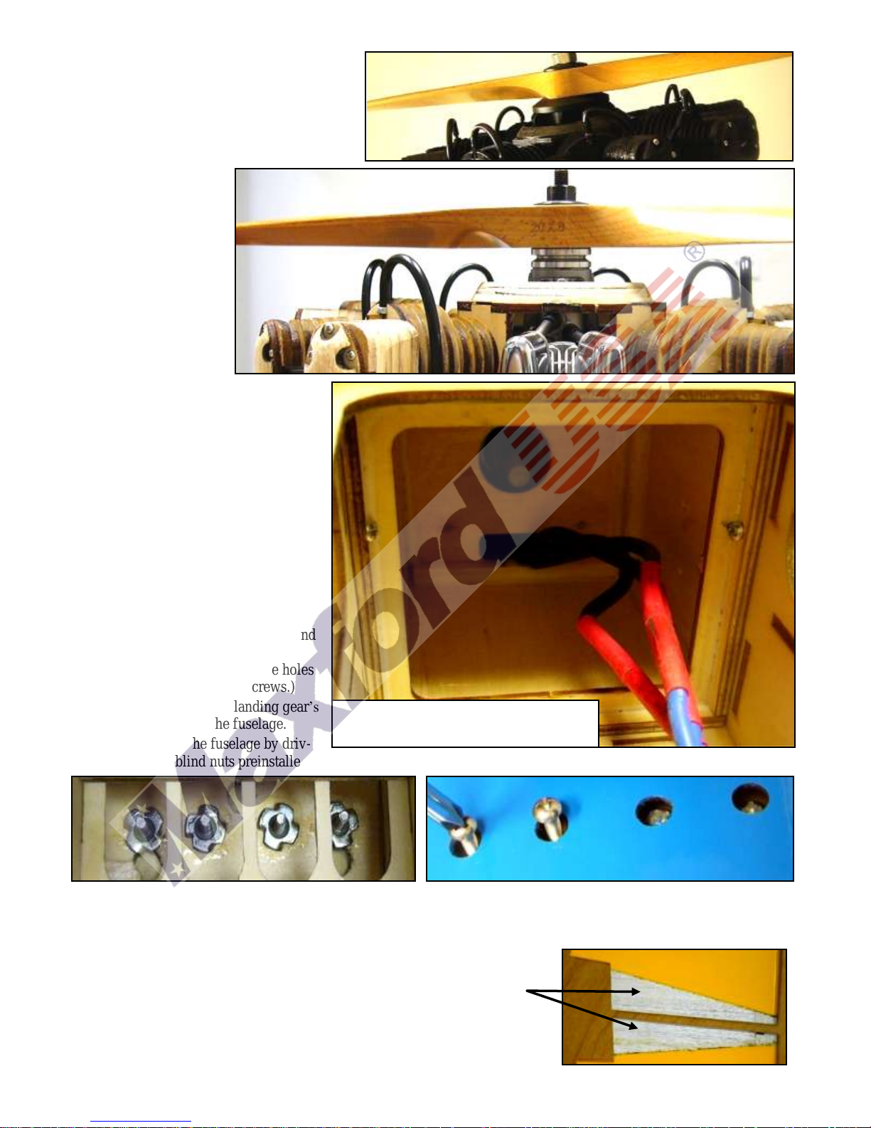
9. If you use a glow engine: Install the fuel
tank inside the engine mounting box. If
you use an electric motor: Insert a piece of
foam rubber (not included) inside the
front of the engine mounting box to
cushion and protect your flight battery.
10. Use epoxy to glue 3 pieces of wood spaced
equally behind the nose ring. When the
glue is fully cured, secure the dummy
engine to the nose by driving 3 wood
screws through the dummy engine‟s
mounting ring, through the nose ring and
into the added wooden.
(SUGGESTION: Drill small guide holes
before driving in these wood screws.)
11. Slide the upper ends of the landing gear‟s
struts into their slots in the fuselage.
12. Secure the struts to the fuselage by driv-
ing bolts into the blind nuts preinstalled in the fuselage.
13. Slide the lower wing‟s composite wing rods into their openings and midway through the fuselage.
14. Test-fit the elevator joiner and both halves of the horizontal stabilizer into their openings at each side of the fuselage.
(NOTE: Position the horiz. stab. fully forward for clearance to insert the elevator joiner in step 51 on page 9.)
15. To ensure good wood-to-wood glueing surfaces between the horizontal stabilizer
and the fuselage, remove the Mylar from the parts of the horizontal stabizer that
will be captured inside the openings in the fuselage as pictured at the right.
Page 6 of 18 Copyright 2015 – PT17 / S150209
 Loading...