

Maxford USA NIEUPORT 28 ARF Instruction Manual
Copyright 2015 - N28 / S160127
Entire contents – Copyright 2015
11//55 N
NOTE: Shown with windshield, WWI pilot figure,
scale machine guns, motor and propeller. These
optional items are not included with the ARF.
RRAADDIIO
NIIEE
O
CCOONNTTRROOL
IINNSSTTRRUUCCTTIIOON
UPP
U
L
ORRTT 2288 AARRFF
O
I
WWWWI
MMOODDEEL
N
MMAANNUUAAL
L
AAIIRRPPLLAANNEE
L
Congratulations on your acquisition of Maxford USA’s Nieuport 28 ARF!
The Nieuport 28 was a French biplane fighter flown during World War I, designed by Gustave Delage and built by Nieuport,
also known as Nieuport-Delage – a French airplane company famous for racers before World War I and fighter aircraft during
World War I and between the wars.
Retaining many of the Nieuport 17’s best features, the Nieuport 28 was a lightly built, highly maneuverable fighter: It had a
more powerful engine; carried twin synchronized machine guns; its ailerons were fitted only to the lower wing; and it had twospar wings – top and bottom – in place of the earlier Nieuport types’ sesquiplane (a biplane with one long wing and one short one
above or below it).
The Nieuport 28 was the first aircraft to see service in any American fighter squadron. By the time the Nieuport 28 became
available in early 1918, it was already considered “surplus” from the French point of view. Their SPAD XIII was a superior
aircraft in most respects and had already become firmly established as the standard French fighter. (A 1/5-scale ARF SPAD XIII
is also available from Maxford USA at www.maxfordusa.com.)
When the Nieuport 28 was offered to the United States, it was immediately accepted by the American Expeditionary Force,
and 297 Nieuport 28s were put into service in the 27th, 94th, 95th and 103rd Aero Pursuit Squadrons.
Several well-known WWI American pilots, including 26-victory American ace Captain Eddie Rickenbacker and Lieutenant
Quentin Roosevelt – the youngest son of former President Theodore Roosevelt – flew Nieuport 28s.
Sadly, on July 14, 1918, just 4 months before his 21st birthday, Lieutenant Roosevelt’s Nieuport 28 was downed behind enemy
lines, felled by two machine gun bullets which struck him in the head. His body was buried at the crash site by the Germans.
Twenty-six years later, following the World War II D-Day invasion of France, Quentin's brother, Brig. Gen. Theodore Roosevelt,
Jr. died of a heart attack on July 12, 1944 and was buried at the Omaha Beach War Memorial. Quentin’s remains were then
reinterred beside his elder brother.
This model of the Nieuport 28 is a new design with improvements over previous products. It is constructed mainly of laser-cut
balsa and light ply, finished with a Mylar film covering patterned after the aircraft flown by 94th Aero Squadron’s ace pilot Eddie
Rickenbacker, and may be special-ordered with the option of a flat-finish or as a fabric-covered prepainted ARF.
We invite you to enjoy the pride of ownership and the joy of flying your high-
quality balsa and light-ply almost-ready-to-fly version of this historic aircraft.
Page 1 of 17
Copyright 2015 - N28 / S160127
TABLE OF CONTENTS
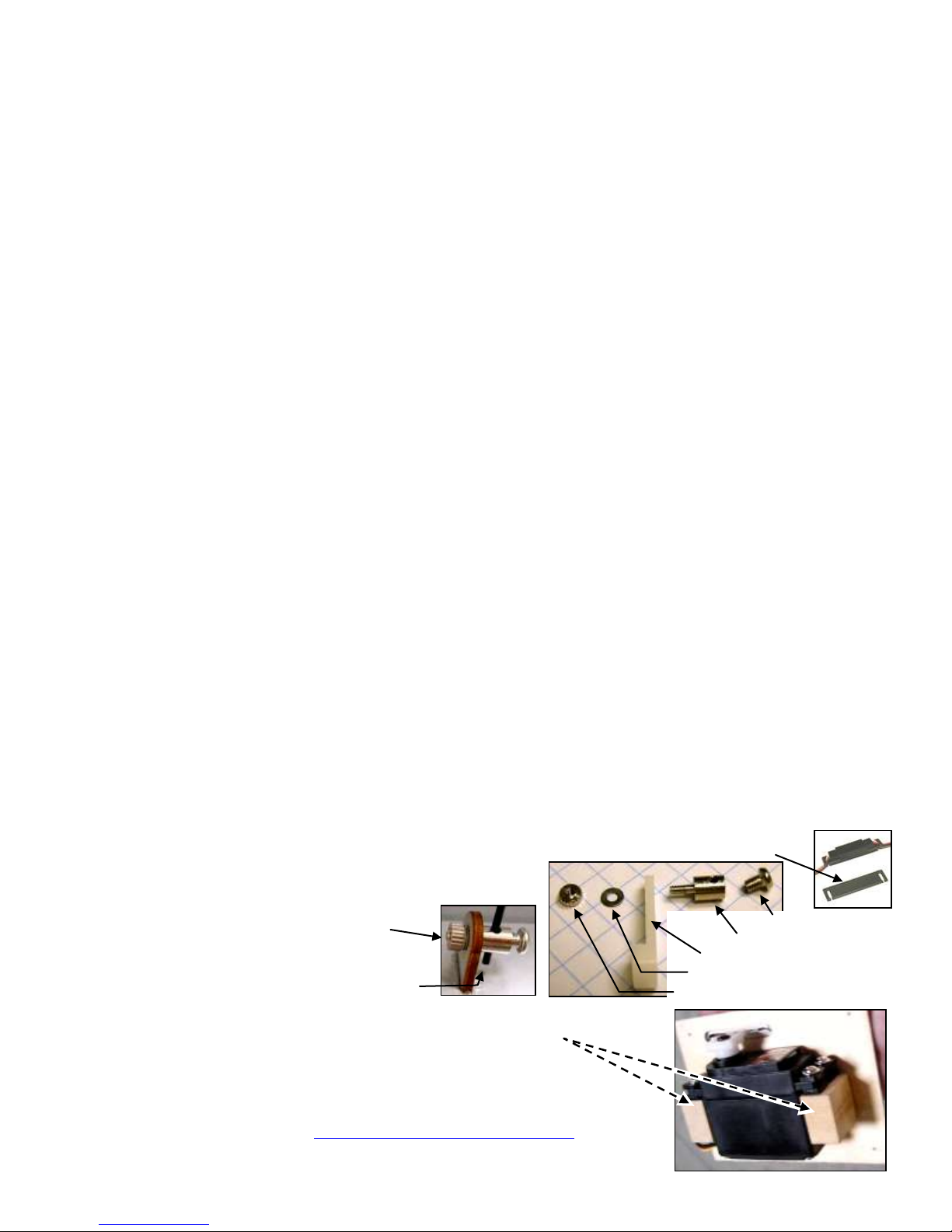
Clamping bolt
Connector body
Control arm (or mounting tab)
Washer
Mounting nut
I. Important safety precautions & assembly tips .... 2
II. Warranty, liability waiver, and return policy ..... 3
III. Special features of this Nieuport 28 model ........ 4
IV. Specifications ..................................................... 4
V. Parts List ............................................................. 4
VI. Assembly photo-instructions ......................... 5
VII. Setup and adjustments ................................. 15
VIII. Preparation for transport and field setup ..... 16
IX. Preflight checks ........................................... 16
I. SAFETY PRECAUTIONS & ASSEMBLY TIPS:
(IMPORTANT – READ THIS SECTION BEFORE YOU BEGIN ASSEMBLY)
1. This product should not be considered a toy, but rather a sophisticated, working model that functions much like a full-scale
airplane. Because of its performance capabilities, this product, if not assembled and operated correctly, could cause injury
to you or spectators and damage to property. Maxford USA provides you with a high-quality, thoroughly tested model
airplane kit with assembly instructions. However, the quality and capabilities of your finished model airplane depend on
how you assemble it, and your safety depends on how you use and fly it. Any testing or flying of this model airplane is
done entirely at your own risk.
2. Assemble this model airplane according to these instructions. Do not alter or modify the model beyond the assembly and
power system options covered in these instructions, as doing so may result in an unsafe or unworkable model. In a few
cases the instructions may differ slightly from the photos; in those instances the written instructions should be considered
as correct. If you have a question or concern about these instructions, before you proceed with assembly of this product,
contact your dealer or speak to a Maxford USA customer service representative at 562-529-3988 (Monday through Friday,
except national holidays, 9 AM to 5 PM Pacific time).
3. While this kit has been flight-tested to meet or exceed our rigid performance and reliability standards in normal use, if you
elect to perform any extremely high-stress flying, such as racing or advanced aerobatics, or if you install a larger power
system than specified, you (the buyer or user of this product) are solely responsible for taking any and all necessary steps
to reinforce the high-stress points and/or substitute hardware that is more suitable for such increased stresses.
4. Throughout the lifetime of this model, use only the Maxford USA-recommended or same-sized engine or motor and a new
or well-maintained radio control system and batteries recommended by the maker of your motor and radio system.
5. It is your responsibility to install the R/C system and other components in such a way that this model airplane passes all
applicable safety/range tests and that the power system and controls operate correctly and smoothly.
6. Recheck the operation of this model airplane before every flight to ensure that all equipment is still operating correctly and
that the model has remained structurally sound. Also before every flight, check all electrical and structural connections; do
not fly without properly connecting or replacing any that you find poorly connected, damaged or worn.
7. Before you begin assembly of this model airplane, read all instructions and test-fit each part to ensure you fully understand the
instructions and that no parts are missing, damaged or unsatisfactory. Temperature and/or humidity differences between the
factory, our warehouse and your home or workshop may dictate the need for slight adjustments to the wings, struts and/or the
vertical or horizontal stabilizer’s mounting surfaces to ensure proper alignment; however, we recommend you contact us before
you attempt any such adjustment(s).
8. To help ensure the security of any in-line servo-type connections, optional Maxford USA servo-extension
safety clips are recommended.
9. Assemble EZ-Link connectors (which may be included or an
option for this model). As shown at the right, when
applying threadlock compount or CA adhesive,
be careful to NOT glue the EZ-Link connector to the
control arm or mounting tab; also be careful to not
let the pushrod rub or bind against nearby surfaces.
10. As shown at the right, this model allows customers some choice in aileron servo selection:
a. Test-fit your aileron servos and the supplied wood mounting pedestals to the servo
hatch covers.
b. Use epoxy to attach the mounting pedestals to each servo hatch cover. Use the
hardware provided with your servos to mount the aileron servos to their hatch covers.
c. Using your radio or a servo tester, center the aileron servos. (You may be interested to
learn more about servo testers at http://www.maxfordusa.com/servo.aspx.)
Page 2 of 17
Copyright 2015 - N28 / S160127
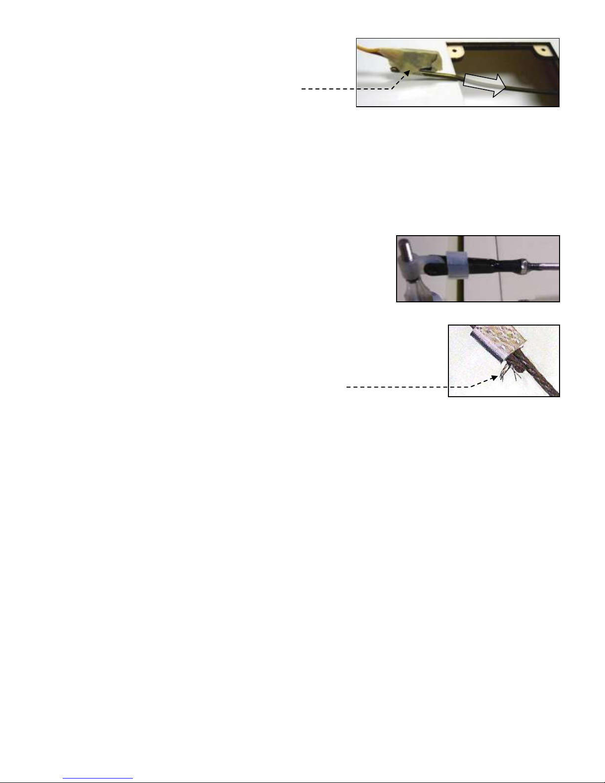
d. String may be supplied to pull your servo’s lead and servo extension
through the wing to your radio receiver; however, you may find it
easier to use masking tape to temporarily attach the connector to the
end of a length of coat-hanger wire, then use the wire to pull the lead
and connector through the airframe as shown at the right.
e. Guide the servo into the servo bay, cover the servo bay with the
servo-hatch and secure the hatch with screws or glue.
11. After you have determined each servo-mounting-screw’s location, apply thin CA adhesive to harden the wood where the
servo’s mounting screws will be inserted.
12. If Mylar hides a CA hinge’s slot, find and open the slot by carefully pressing with a fingernail or sharp hobby knife.
13. Use the tip of a hot soldering iron to burn and remove any Mylar covering material to obtain good wood- to-wood gluing
surfaces at the horizontal and vertical stabilizers.
14. We recommend 30-minute epoxy for permanent attachment of critical parts such as where the horizontal and vertical
stabilizers attach to the fuselage.
15. If you have concern about the security of any factory fabrication procedure(s), we recommend you apply 30-minute epoxy
around the perimeter of such part(s) as an extra safety precaution.
16. We recommend use of a thread-locking compound to secure all hardware from
vibration. Also, once the included clevises are adjusted, we suggest you coat
each clevis and rod with epoxy to securely and safely affix each clevis to its rod.
As a safety precaution, always check each clevis before and after each flight.
17. This model includes some fiberglass or carbon-fiber reinforced parts. If you drill,
grind or sand a fiberglass or carbon-fiber reinforced part, always wear safety
goggles, a particle mask and rubber gloves to guard yourself from eye, skin and respiratory-tract irritation; never blow into
the part to remove fiberglass or carbon fiber dust (the dust may blow back into your face).
18. Check the Mylar covering material’s joints and surfaces; if necessary, carefully use an iron
(do NOT set the iron’s temperature too high) to secure the edges and to tighten any loosened
areas. Recheck and retighten from time to time.
19. For your safety, do NOT leave any strands of wire poking out from the end of any crimp tube.
Exposed small steel strands can be sharp enough to cut or abrade skin!
20. Minor production details may vary.
21. If you are not an experienced ARF assembler or R/C pilot or have not flown this type of model before, we strongly urge
you to get assistance from an experienced ARF assembler or R/C pilot.
22. Read all instructions included with your batteries and charger. Failure to follow all instructions could result in permanent
damage to the battery, its surroundings, and bodily harm! If you crash this model airplane, check whether the batteries are
damaged. Do NOT attempt to use or recharge a damaged battery.
II. WARRANTY, LIABILITY WAIVER, AND RETURN POLICY
Maxford USA guarantees this kit to be free from defects in material and workmanship at the time of purchase. All of our
products have been inspected in our factory and are checked again when shipped from our warehouse.
However, Maxford USA cannot directly control the materials you may use nor your final-assembly process. Therefore,
Maxford USA can NOT in any way guarantee the performance of your finished model airplane. Furthermore, in purchasing
this product, you (the buyer or user of this product) exempt, waive, and relieve Maxford USA from all current or future
liability for any personal injury, property damage, or wrongful death, and if you (the buyer or user of this product) are
involved in any claim or suit, you will not sue Maxford USA or any of its representatives.
If you do not fully accept the above liability and waiver, you may request a return merchandise authorization number (RMA#)
as explained in item 2, below.
If you think there is a missing part or any shipping damage, please read our after-sales service and return policy as outlined
below.
1. Inspect your order upon delivery for any shipping damage or missing part. If you find a problem you must contact us within
10 days from receipt of your purchase by calling (562) 529-3988, Monday through Friday, except holidays, between the
hours of 8:30 AM and 5 PM Pacific time. During this telephone conversation, and with your support, we will determine how
to resolve your concern. (Note: Maxford USA batteries are sold without warranty and are not eligible for return or credit.)
2. To request an RMA#, call (562) 529-3988, Monday through Friday, except holidays, between the hours of 8:30 AM to 5 PM
Pacific time. If we elect to issue you an RMA#, you must clearly mark this RMA# on the outside of the package. (No return
or exchange will be authorized after 10 days from the date of your receipt of the product; any package delivered to us without
a Maxford USA RMA# is subject to being returned to the sender, as received, with return postage payable upon delivery.)
Page 3 of 17
Copyright 2015 - N28 / S160127
Returned merchandise must be in its original condition as received from Maxford USA, with no assembly or modification, in
the original packing materials, complete with all manuals and accessories. Return shipping and insurance charges must be
prepaid by you, the buyer.
3. Returned merchandise that is accepted by Maxford USA for credit is subject to a 10% to 20% restocking fee (the final
amount will be determined by Maxford USA upon receipt and examination of the returned merchandise).
Return Address:
Maxford USA RC Model Distribution, Inc.
15939 Illinois Avenue #C
Paramount, CA 90723 (Print the RMA# issued by Maxford USA on the package near the address.)
III. SPECIAL FEATURES OF THIS NIEUPORT 28 MODEL
Wing panel sets are removable from the fuselage
for ease of storage and transport.
Prepainted fiberglass cowl with
Max Cowling ‘invisible’ attachment
system.
Each aileron is separately operated
by its own in-wing servo.
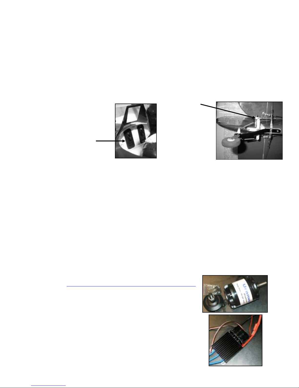
Precut dashboard openings for your
ignition and radio switches.
Wing support kit is included for safe
transport and storage.
Streamlined landing gear.
Includes preinstalled cockpit coaming, dummy engine,
fuel-system venturi and air intake tube.
Pull-pull rudder.
Stick-on decal set.
Supplied machine gun
mounting platforms.
(Scale-looking
machine guns are
optional.)
Photo-enhanced
assembly instructions.
IV. SPECIFICATIONS
Wingspan ................................................................................................................................ 68 inches
Wing Area ................................................................................................................. 920 square inches
Length ..................................................................................................................................... 56 inches
ARF weight .................................................................................................... 10 pounds and 6 ounces
Flying weight ................................................................................................. 11 pounds and 14 ounces
Engine required (Not included) ...... 26cc gas, 90 to 120 glow or an equivalent electric power system
such as the Uranus 638109 brushless motor and 100 Amp High Voltage Brushless Controller
Propeller (Not included) ................................................................................................... 18 to 20 inch
(as recommended for your power system)
Radio system (Not included) ....................................... Minimum of 4 channels and 5 standard servos
or 4 standard servos and an electronic speed control, if you use an electric power system
V. PARTS LIST
1. Items you must supply to complete this Nieuport 28:
26cc gas engine, 90 to 120 glow engine, or an equivalent electric-powered
motor. (See http://www.maxfordusa.com/brushlessmotorandcontroller.aspx
for detailed information about Maxford USA electric power systems.)
Propeller.
Five(5) standard-sized servos [four(4) standard servos if you use an electric
power system], two(2) 18-inch extensions, one(1) 6-inch Y-connector, and a
minimum of a 4-channel radio control system.
5- and 30-minute epoxy or aliphatic resin glue, thin and thick
Cyanoacrylate (CA) adhesives.
Pliers, Allen wrenches, a high speed rotary tool, scissors and masking tape.
Optional upgrade items: Scale machine guns; windshield; WWI pilot figure;
and Scimitar-type propeller.
(All dimensions and weights are approximate.)
Page 4 of 17
Copyright 2015 - N28 / S160127
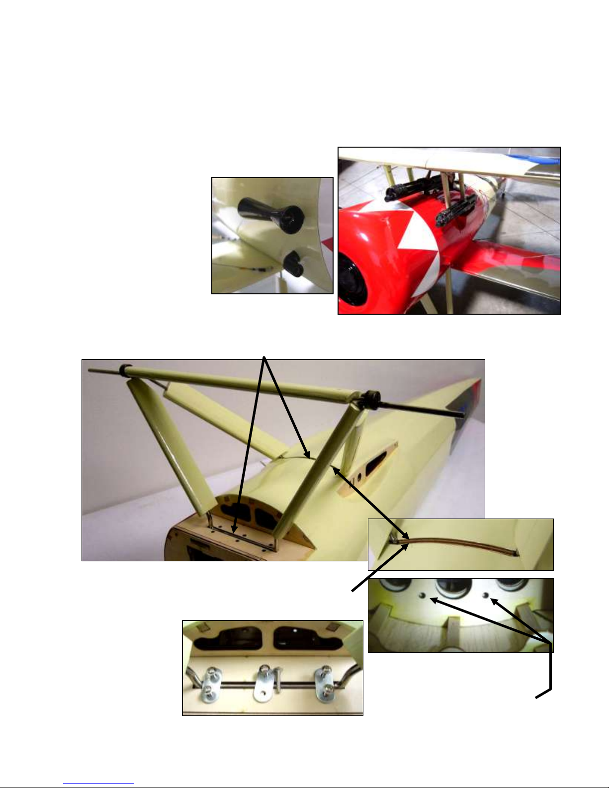
2. Items included with this Nieuport 28:
NOTE: You have the choice of securing
the rear landing gear struts’ retainer
into the fuselage by driving bolts into
the preinstalled blind nuts pictured
above, or you may simply glue the
retainer into its opening in the fuselage.
NOTE: Shown with optional windshield,
WWI pilot figure and scale machine guns.
Precovered fuselage, upper and lower-wing panels and upper-wing’s center section, vertical and horizontal
stabilizers, rudder and elevator halves, with all hinge openings precut.
Prepainted fiberglass cowl.
Rudder pull-pull cables and aileron and elevator pushrods.
Wing joiners, preformed cabanes and struts, and all required control horns, hinges, linkages, wing and tail flying
wires and related hardware, including self-threading and machine screws and nuts (except those normally supplied
with the servos and a glow or gas engine or electric power system).
Fuel tank with clunk and fuel lines.
Streamlined landing gear with scale-like wheels.
Complete set of scale
markings.
Magnetically secured
cockpit hatch and coaming.
Simulated fuel-system
venturi and air intake
tube.
VI. ASSEMBLY PHOTO-INSTRUCTIONS
1. Pull the engine mounting box out of the nose and set it aside. (NOTE: If the engine mounting box seems ‘stuck’ in the nose,
carefully reach in through the cockpit and push it out from the inside.)
2. Position the fuselage onto its back and insert the landing gear’s cross-struts into the slots in the fuselage as shown below.
3. Position the wooden landing gear retainer between the landing gear’s rear
struts, then press the rear strut and retainer into the fuselage until the
outer edge of the retainer is flush with the bottom surface of the fuselage.
4. As shown at the right, secure the retainer with glue or with 2 bolts.
5. Test-fit the three metal landing
gear retainers over the landing
gear’s front strut.
6. Drive 6 ea. bolts into the 6 ea.
blind nuts inside the fuselage
to secure the landing gear’s
front retainers.
Page 5 of 17

Copyright 2015 - N28 / S160127
7. Using a total of 4 wheel collars, attach both main wheels to the
2
1
landing gear’s axles with wheel collars and secure with
threadlock.
8. Test-fit the hatch: (1) Lift the rear of the hatch above the magnet
and toward the rear; (2) Lift the front and maneuver the hatch’s
corners to clear the edge cockpit. (Note: You may remove a bit
of wood from the hatch’s front corners for added clearance.)
9. Slide the lower wing rod midway through the fuselage.
(NOTE: Apply a small amount of Graphite Dry Lubricant to the wing rods if necessary to help them slide.)
10. Temporarily position the lower left and right wing panels onto the lower
wing rod.
(Note: As the lower wing panels near the fuselage, fit the lower wing
panel’s alignment pins into their openings
in the fuselage as shown at the right.)
11. Cut away the Mylar covering the slotted
opening in the horizontal stabilizer for the
vertical stabizer and test-fit the vertical
stabilizer to the horizontal stabilizer.
12. Test-fit the horiz. stabilizer to its platform
at the top-rear of the fuselage. Remove the
Mylar at the bottom of the horiz. stabizer
to ensure a good wood-to-wood glueing
surface between the horiz. stabilizer and
the fuselage as pictured below.
13. As shown at the right, place
flex-type drinking straws (not
supplied) over both of the
threaded ends of the elevator’s
pushrod.
14. Guide the pushrod into the nose
and through the rectangular
openings on each side of the
fuselage as follows:
a. Insert the pushrod and straws into the fuselage until the free ends of the straws are near the rectangular openings in the
sides of the fuselage. (NOTE: You may slightly bend the 2 ends of this forked pushrod toward each other if necessary
to more easily fit the forked pushrod and straws into and through the fuselage.)
b. Guide the end of one straw out its nearest opening.
c. Guide the end of the remaining straw out through the opening on the other side of the fuselage.
Page 6 of 17
 Loading...