

Maxford USA Neptune Boatplane ARF Twin Instruction Manual

GLOW/ELECTRIC 60-INCH WINGSPAN
...................................................
..................................
.............................................................
................................................
........
........
NEEPPTT
N
U
U
NEE
N
B
B
O
O
ATT
A
PPLLA
A
NEE
N
A
A
RFF
R
WII
TTW
N
N
INSTRUCTION MANUAL
This Neptune Boat Plane ARF Twin is the twin-engine version of our earlier single-engine Neptune.
The engine pods sit atop carbon-fiber tubes large enough for any wires you may need to install between
the engine pods and the fuselage. The supplied three-piece engine pods may be used for 40-class glow
engines, throttle servos and fuel tanks or for electric motors.
Both aileron servos are located safely inside the fuselage near the center of the wing. The wing rod is a
lightweight composite material. The nose compartment is the perfect location if you decide to add an
onboard glow-plug driver, for an electric power system’s ESCs and flight batteries, or to add any weight
to fine-tune the center of gravity. (The hatch arrives out-of-the-box covered
over. To access this compartment, simply cut the covering material around
the edges of the hatch.)
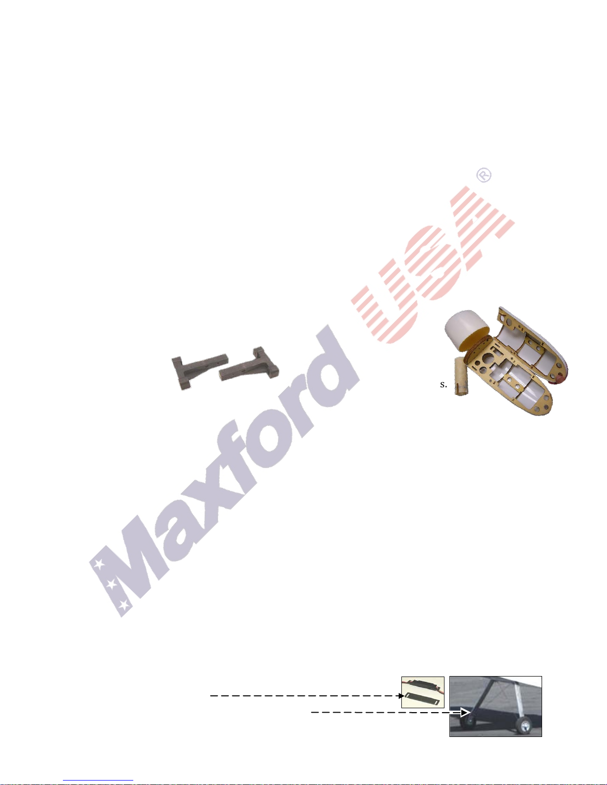
You could also enjoy this airplane on land with the optional landinggear and tail skid set as pictured at the right. Its color scheme is bright
and visible both in the air and on the water.
We invite you to enjo y the pr ide of ownership and the joy of fly in g thi s
high quality balsa, c arbon-fiber, fi be rgl a ss and li gh t-ply almost-ready-to-fly aircraft.
Table of Contents:
Specifications
I.
II.
Parts list
III.
Special features
IV.
Important things customers must know
V.
Storage, field setup & preflight checks
Copyright Maxford USA 2017 Page 1 of 12 S171201
2 VI. Safety precautions & assembly tips
2 VII. Limited warranty, liability waiver & re turn policy ...... 5
3 VIII. Photo instructions and assembly notes ......................... 6
3 IX. Initial setup, adjustments and preflight checks ............. 11
3
4
I. SPECIFICATIONS*
• Precovered fuselage, wing panels, ailerons,
empennage with elevator and rudder.
Twin pods with cowls
for engines or motors.
• Two sets of 40-
class glow-engine
mounts.*
Composite mounting
pedestals for engine
or motor mounting pods.
Wing-tip floats and tail-bracing struts.
CA hinges and precut slots.
• Composite wing joiner, control horns and
related hardware (except items normally
supplied with servos, engines and motors).
Aileron, rudder and elevator pushrods and
related linkages.
This illustrated instruction manual.
Fuel tanks, complete with metal tubing, clunks and fuel lines.*
*(NOTE: engine mounts and fuel tanks can be ordered with this boatplane at no charge.)
• Wingspan ..................................................................................................................................................................... 60 inches
• Length ........................................................................................................................................................................... 55 inches
• Wing area ................................................................................................................................................... 713 square inches
• ARF-only weight .................................................................................................................................... 6 pounds 6 ounces
• Flying weight ........................ Approx. 9 pounds 4 ounces (depending on your power and radio systems)
• Center of gravity (CG) ....................................................................... 3¾-inches to 4½-inches (approx. 102 mm)
back from the leading edge of the wing
• Radio system (not included) ................................... Minimum of 4 channels with four standard servos and
two mini servos with internal combustion engines,
or four standard servos if electric powered
• Recommended power .................. Twin 40-class 2C glow engines or equivalent-powered electric motor
systems (such as a pair of Maxford USA 35425 motors and 60A ESCs)
• Propeller .................................................................................. 10- to 11-inch diameter by 6- to 7-inch pitch or as
recommended by the maker of your power system
*(Dimensions and weights are approximate.)
II. PARTS LIST
1. Included items
•
•
•
•
2. Items you must supply to complete this ARF
• Cyanoacrylate (CA) and epoxy adhesives and optional threadlock compound.
• Common household shop tools (screwdriver, pliers, etc.).
• Two 40-class 2-cycle glow engines or an equivalent electric power (EP) system.
• A pair of 10- or 11-inch dameter by 6- or 7-inch pitch propellers or as recommended by the maker of
your power system. (Propellers may both rotate in the same direction, as done during all test flights.)
• A four- (or more) channel radio system.
• Four standard servos (such as Hitec HS311) plus two mini servos (such as Hitec HS55) when using an
internal combustion engine, or four standard servos (Hitec HS311) if using an electric power system.
• Using either twin glow engines or an electric power system: two 10-inch extensions and a Y-harness
(depending on customer’s choice of engine or motor setup).
•
•
•
3. Optional items you may choose to add
• Servo extension safety clips.
• Landing-gear set for land-based flight operations.
Copyright Maxford USA 2017 Page 2 of 12 S171201

III. SPECIAL FEATURES
• Classic balsa and plywood construction.
• All required openings are predrilled and/or precut.
• Each aileron is separately operated by its own servo, giving customers the option of flaperons (if
permitted by customer’s radio system) and both aileron servos are safely located within the fuselage.
• The wing is easily removed for transport to and from the lake for storage.
• All major assemblies are preassembled and either precovered in Mylar or prepainted.
• Designed for glow engines, but may be easily converted for electric power.
• A supplied removable hatch gives customers a wide range of choices for using space inside the nose.
IV. IMPORTANT THINGS CUSTOMERS MUST KNOW BEFORE ASSEMBLING THIS ARF
Please read and follow all instructions carefully, even if you are an experienced builder. Any assembling,
testing or flying of this airplane is done entirely at your own risk. If you use a receiver battery to power
your radio system and you are using an electric power system, do not attempt to combine the output of
your radio’s battery with any battery-eliminator circuit.
V. STORAGE, FIELD SETUP & PREFLIGHT CHECKS
1. Check the Mylar covering material’s joints and surfaces. If necessary, carefully use an iron on medium
heat to secure the edges and to tighten any loosened areas. Recheck and retighten from time to time; be
careful to not apply too much heat as you secure edges or tighten the Mylar. If any trim becomes
loosened, press it down and/or apply clear tape. Never apply heat to any trim or plastic part.
2. Ensure the propellers are securely attached to your engines or motors and that they remain undamaged
and correctly balanced.
3. To remove the wing:
a. Remove the bolts securing the wing to the fuselage near the trailing edge of the wing.
b. Slide the wing a few inches toward the tail, disconnect the servo extensions and glow-plug driver
wires if used, or motor wires if using an electric power system, then lift the wing fully away from the
fuselage. If desired for transport or storage, the wing panels may also be separated and the wing rod
may also be removed. Be careful to retain the removed wing attachment bolts, any optional Maxford
USA servo-extension safety clips you may have installed, and the wing rod if removed from the wing
panels.
4. To reinstall the wing, reverse the above procedure:
a. If the wing panels were separated, slide the wing panels onto the wing rod. Position the wing above
the fuselage and reconnect the servo extensions, optional Maxford USA servo-extension safety clips
and any other optional wiring (or motor wires if using an electric power system).
b. Slide the wing forward and insert the carbon fiber ‘pins’ in the leading edge of the wing into the
former at the front of the wing saddle, then use the wing attachment bolts to firmly secure the wing
to the fuselage.
5. Preflight checks:
a. If any weight was added in the nose or tail to adjust the CG, ensure it remains secure.
b. Double-check the condition and secure attachment of your propellers and batteries.
c. Make certain all screws, clevises and other mechanical and electrical connections are secure.
(Do not attempt to fly with any damaged or frayed electrical or mechanical connection.)
d. Double-check all control directions and the amounts of control throws.
s with all radio-controlled model airplanes, this model must pass the radio range ground check
e. A
recommended by your radio’s manufacturer or you may not fly safely.
f. Make it a habit to set your transmitter’s throttle control safely to minimum before turning ON your
transmitter and receiver and starting your engines or connecting your Lipo flight batteries.
g. Setup and operate your radio-control and power systems according to their manufacturer’s
instructions and follow the guidelines offered by the Academy of Model Aeronautics, your local R/C
club, and concerned manufacturers, who all wish to help ensure your safe enjoyment of this hobby.
Copyright Maxford USA 2017 Page 3 of 12 S171201
VI. SAFETY PRECAUTIONS & ASSEMBLY TIPS
Clamping bolt
(IMPORTANT – READ THIS SECTION CAREFULLY BEFORE YOU BEGIN ASSEMBLY)
1. This product should not be considered a toy, but rather a sophisticated, working model that functions
much like a full-scale airplane. Because of its performance capabilities, this product, if not assembled and
operated correctly, could cause injury to you or to spectators and damage to property. Maxford USA
provides you with a high-quality, thoroughly tested model airplane kit and written/photo assembly
instructions. However, the quality and capabilities of your finished model airplane depend on how you
assemble it, and your safety depends on how you use and fly it. Any testing or flying of this model airplane
is done entirely at your own risk.
2. Assemble this model airplane according to these written/photo instructions. Do not alter or modify the
model beyond any assembly and/or power-system options covered in these instructions; doing so may
result in an unsafe or unworkable model. If the instructions differ from the photos, the written
instructions should be considered correct. If you have any question or concern about the instructions,
before you proceed with assembly of this product, contact your dealer or speak to a Maxford USA
customer service representative at 562-529-3988 (Monday through Friday, except national holidays,
9 AM to 5 PM Pacific Time).
3. While this kit has been flight-tested to meet or exceed our rigid performance and reliability standards in
normal use, if you elect to attempt any high-stress flying, such as racing or aerobatics, or if you install a
larger power system than specified, you (the buyer or user of this product) are solely responsible for
taking any and all necessary steps to reinforce the high-stress points and/or substitute hardware that is
more suitable for such increased stresses.
4. Throughout the lifetime of this model, use only the Maxford USA-recommended power system and a new
or well-maintained radio-control system with fully charged batteries.
5. Before you begin assembly of this model airplane, study the instructions and test-fit each part to ensure
you fully understand the instructions and that no parts are missing, damaged or unsatisfactory. Some
parts may differ slightly from those pictured in this manual. Due to temperature and/or humidity
differences between the factory, our warehouse and your home or workshop, there may be some need for
slight adjustments to these instructions and/or to some mounting surfaces to ensure proper installation
and alignment. We recommend you contact us before attempting any such adjustment.
6. It is your responsibility to install the receiver and to connect the R/C components in such a way that this
model passes all applicable safety/range tests and that the power system and controls operate correctly.
7. Recheck the operation of this model before every flight to ensure all equipment is still operating correctly
and that the model remains structurally sound; also check all electrical, control and structural connections.
Do not fly without replacing any that you find damaged or worn.
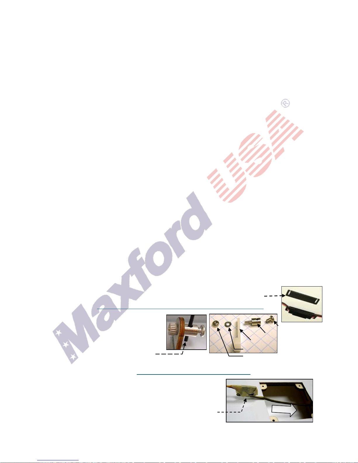
8. To help ensure the security of your servo connections, we recommend using optional
Maxford USA servo-extension safety clips as pictured at the right. (For information
about safety clips see
http://www.maxfordusa.com/servoextensionsafetyclip.aspx
9. Assemble any included or optionally installed
EZ-Link connectors as shown at the right.
When applying threadlock compound, do
glue the EZ-Link connector to the control arm
or mounting tab, and be careful to not let any
pushrods bind against any nearby surfaces.
NOT
Connector body
Control arm (or tab)
Washer
Mounting nut
10. Use your radio system or a servo tester to center your servos before installation. (You may be interested
to learn more about servo testers at
http://www.maxfordusa.com/servo.aspx.)
.)
11. String may be supplied to pull your servo’s leads and/or servo
extensions or other wiring through the wing or fuselage; however,
you may find it easier to use masking tape to temporarily attach
the end of the wire to a length of coat-hanger wire, then use the
wire to pull the lead through the airframe as pictured at the right.
12. After you determine each wood-screw’s location, drill a small guide
hole then apply thin CA adhesive to harden and strengthen the wood where the screws are to be installed.
Copyright Maxford USA 2017 Page 4 of 12 S171201
 Loading...