

Maxford USA Gee Bee Y Instruction Manual

I.
Specifications ......................................................
2 VI.
Storage, field setup & preflight checks ........................
3
II.
Improvements in this new version ...................
2 VII.
Safety precautions & assembly tips ..............................
4
III.
Parts list ................................................................
2 VIII.
Limited warranty, liability waiver & return policy ....
5
IV.
Special features ...................................................
3 IX.
Photo instructions and assembly notes ........................
6
V.
Important things customers must know ...........
3 X.
Initial setup & adjustments ............................................
13
V
V
SSPPOORRTT--SSCCAALLEE AARRFF RR//CC M
The Gee Bee Model Y Senior Sportster was one of the famous “Golden Age” racers created by
Granville Brothers Aircraft in the early 1930s. It was a low-wing, strut-and-wire-braced
monoplane with open cockpits. To a great extent, it was an enlarged, two-seat version of the
single-seat Sportster. Only two were ever b uilt; both were unfortunately destroyed in accidents.
R
EER
S
S
.
2
.
E
E
2
NII
N
2277%
%
O
O
G
G
R
R
E
E
S
S
E
E
P
P
B
E
E
B
O
O
E
R
R
E
M
T
T
M
S
S
O
O
T
T
D
D
E
E
ELL
E
R
R
MOODDEELL AAIIRRPPLLAANNEE
Y
Y
This radio-controlled almost-ready-to-fly (ARF) 27% sportscale model is based on the full-scale Gee Bee Model Y Senior
Sportster. It comes 99% preassembled by our factory, includes
a prepainted fiberglass cowl and wheel pants, and includes a
spring-loaded tail wheel to aid in ground handling.
We invite you to enjoy the pride of ownership and the joy of flying this beautiful ARF
sport-scale model aircraft.
Table of Contents:
Copyright Maxford USA 2017 Page 1 of 14 S171108
I. SPECIFICATIONS*
More robust landing-gear struts.
Included Maxford-designed Maxlok cowl ring
Additional wing attachment bolts.
Included wing and tail wires
Large, easily removable cockpit hatch.
Twin-cockpit Super Sportster design
Precovered fuselage, wing panels, ailerons,
empennage, elevators and rudders
Adjustable mounting box for engine
(or electric motor)
Top-of-wing struts
Metal wing- and tail-
bracing wires
Hardware package
True-to-scale dummy engine; mains and tail landing-gear struts with wheels; prepainted wheel
pants and fiberglass cowl
Wingspan ..................................................................................................................................................................... 97 inches
Length ........................................................................................................................................................................... 69 inches
Wing area ............................................................................................................................................... 1,577 square inches
ARF-only weight ................................................................................................................................................. 16½ pounds
Flying weight .................................................... Approx. 25 pounds (depending on power and radio systems)
Center of gravity (CG) .................................................. 5 1/4-inches (134.5mm) from the wing’s leading edge
measured next to the fuselage
Radio ......................................................................................................................................... Minimum of 4 channels and
6 standard servos with an internal combustion engine or 5 standard servos if electric powered
Recommended power ............................................................................................. 50CC-class 2-cycle gas engine or
equivalent power brushless-motor electric power system
Propeller ........................................................................................... 20- to 22-inch diameter by 8- to 10-inch pitch
or as recommended by the maker of your power system
*(Dimensions and weights are approximate.)
II. IMPROVEMENTS IN THIS NEW VERSION BY MAXFORD USA
III. PARTS LIST
1. Included items
2. Items you must supply to complete this ARF
Cyanoacrylate (CA) and epoxy adhesives and optional threadlock compound.
Common household shop tools (screwdriver, pliers, etc.).
50CC-class 2-cycle gas engine or an equivelant electric power (EP) system.
A 20- to 22-inch propeller or as recommended by the maker of your power system.
A four- (or more) channel radio system with a receiver battery and a radio-system power switch.
Six standard servos (such as Hitec HS311) when using an internal combustion engine, or
five standard servos when using an electric power system.
Two 10-inch, three 24-inch extensions and one Y harness or two 6-inch extensions (depending on your
choice of radio equipment and setup).
3. Optional items you may choose to add
Servo extension safety clips.
Scale pilot figures, such as the prepainted 1/5-scale pilot and
copilot pictured at the right designed and manufactured by
Maxford USA.
If using an electric power system, this ARF may be ordered with an
optional flat-finish or fabric covering. (For details, see
http://www.maxfordusa.com/flatfinishingarf.aspx.)
Copyright Maxford USA 2017 Page 2 of 14 S171108

IV. SPECIAL FEATURES
Classic balsa and plywood construction, semi-scale model of this historic golden-era aircraft.
All major assemblies are preassembled and either prepainted or precovered in Mylar.
New, strengthened landing-gear struts able to withstand the stresses of less-than-perfect landings.
The engine (or motor) mounting box can slide backward and forward inside the fuselage to fit a wide
range of internal combustion engine or electric motor sizes.
Designed for a gas or glow engine, but may be easily converted for electric power.
The removable cockpit hatch provides LiPo flight battery access for an electric power system.
V. IMPORTANT THINGS CUSTOMERS MUST KNOW BEFORE ASSEMBLING THIS ARF
This is a large-scale airplane. Please read and follow all instructions carefully, even if you are an
experienced builder. Any assembling, testing or flying of this airplane is done entirely at your own risk.
If you use a receiver battery to power your radio system and you are using an electric power system, do
not attempt to combine the output of your radio’s battery with a battery-eliminator circuit.
VI. STORAGE, FIELD SETUP & PREFLIGHT CHECKS
1. Check the Mylar covering material’s joints and surfaces. If necessary, carefully use an iron on medium
heat to secure the edges and to tighten any loosened areas. Recheck and retighten from time to time; be
careful to not apply too much heat as you secure edges or tighten the Mylar. If any trim becomes
loosened, press it down and/or apply clear tape. Never apply heat to any trim or plastic part.
2. Ensure the propeller is securely attached to your engine or motor and that it remains undamaged and
correctly balanced.
3. As with all radio-controlled model airplanes, your Gee Bee Y must pass the radio-range ground check
recommended by your radio’s manufacturer or you may not fly safely.
4. To remove the wing:
a. Remove the bolts securing the wing to the fuselage near the trailing edge at the bottom of the wing.
b. Loose the wing wires by stretching the springs to unhook the top- and bottom-side wing wires from
their anchor points.
c. Slide the wing panels a few inches away from the fuselage, disconnect the aileron servo extensions,
then slide the wing panels fully away from the fuselage and off the aluminum wing rod.
Note: The wing rod may also be removed from the fuselage for transport or storage. Be careful to
secure and retain the removed wing attachment bolts, any optional Maxford USA servo-extension
safety clips you may have installed, and the wing rod if removed from the fuselage. Also secure the
top-side wing struts if they are not glued in.
5. To reinstall the wing, reverse the above procedure:
a. Center the wing rod in the fuselage. Slide each wing panel toward the fuselage and reconnect the
aileron servo extensions and optional Maxford USA servo-extension safety clips. If the top-side wing
struts are not glued in, insert the upper wing struts into their openings in the top of the wing. Guide
the upper wing struts into their slots on each side of the fuselage.
b. Insert and firmly secure the wing attachment bolts and reattach the wing wires.
6. Preflight checks:
a. If any weight was added in the nose or tail to adjust the CG, ensure it remains secure.
b. Double-check the condition and secure attachment of your propeller.
c. Make certain all screws, clevises and other mechanical and electrical connections are secure.
(Do not attempt to fly with any damaged or frayed electrical or mechanical connection.)
d. Double-check all control directions and the amounts of control throws.
e. As with all radio-controlled model airplanes, this model must pass the radio range ground check
recommended by your radio’s manufacturer or you may not fly safely.
f. Make it a habit to set your transmitter’s throttle control safely to minimum before turning ON your
transmitter and receiver and starting your engine or connecting your Lipo flight batteries. Setup and
operate your radio-control and power systems according to their manufacturer’s instructions and
follow the guidelines offered by the Academy of Model Aeronautics, your local R/C club, and
concerned manufacturers, who all wish to help ensure your safe enjoyment of this hobby.
Copyright Maxford USA 2017 Page 3 of 14 S171108
VII. SAFETY PRECAUTIONS & ASSEMBLY TIPS
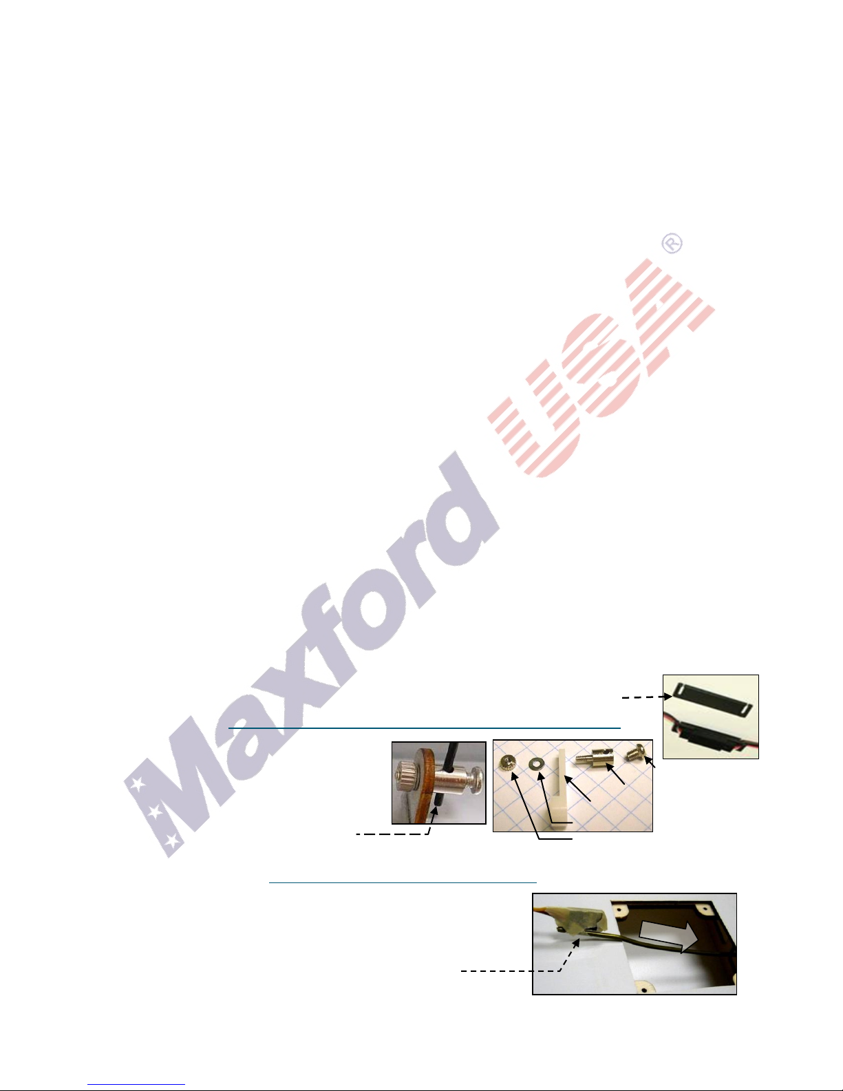
Clamping bolt
Connector body
Control arm (or tab)
Washer
Mounting nut
(IMPORTANT – READ THIS SECTION CAREFULLY BEFORE YOU BEGIN ASSEMBLY)
1. This product should not be considered a toy, but rather a sophisticated, working model that functions
much like a full-scale airplane. Because of its performance capabilities, this product, if not assembled and
operated correctly, could cause injury to you or to spectators and damage to property. Maxford USA
provides you with a high-quality, thoroughly tested model airplane kit and written/photo assembly
instructions. However, the quality and capabilities of your finished model airplane depend on how you
assemble it, and your safety depends on how you use and fly it. Any testing or flying of this model airplane
is done entirely at your own risk.
2. Assemble this model airplane according to these written/photo instructions. Do not alter or modify the
model beyond the assembly and/or power-system options covered in these instructions; doing so may
result in an unsafe or unworkable model. If the instructions differ from the photos, the written
instructions should be considered correct. If you have any question or concern about the instructions,
before you proceed with assembly of this product, contact your dealer or speak to a Maxford USA
customer service representative at 562-529-3988 (Monday through Friday, except national holidays,
9 AM to 5 PM Pacific Time).
3. While this kit has been flight-tested to meet or exceed our rigid performance and reliability standards in
normal use, if you elect to attempt any high-stress flying, such as racing or aerobatics, or if you install a
larger power system than specified, you (the buyer or user of this product) are solely responsible for
taking any and all necessary steps to reinforce the high-stress points and/or substitute hardware that is
more suitable for such increased stresses.
4. Throughout the lifetime of this model, use only the Maxford USA-recommended power system and a new
or well-maintained radio-control system with fully charged batteries.
5. Before you begin assembly of this model airplane, study the instructions and test-fit each part to ensure
you fully understand the instructions and that no parts are missing, damaged or unsatisfactory. Some
parts may differ slightly from those pictured in this manual; temperature and/or humidity differences
between the factory, our warehouse and your home or workshop; there may be some need for slight
adjustments to these instructions or to some mounting surfaces to ensure proper installation and
alignment. We recommend you contact us before attempting any such adjustments.
6. It is your responsibility to install the receiver and to connect the R/C components in such a way that this
model passes all applicable safety/range tests and that the power system and controls operate correctly.
7. Recheck the operation of this model before every flight to ensure that all equipment is still operating
correctly and that the model remains structurally sound; also check all electrical, control and structural
connections; do not fly without replacing any that you find damaged or worn.
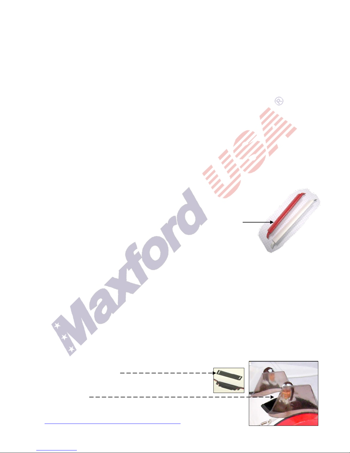
8. To help ensure the security of your servo connections, we recommend using optional
Maxford USA servo-extension safety clips as pictured at the right. (For information
about safety clips see http://www.maxfordusa.com/servoextensionsafetyclip.aspx.)
9. Assemble any included or optionally installed
EZ-Link connectors as shown at the far right.
When applying threadlock compound, do NOT
glue the EZ-Link connector to the control arm
or mounting tab, and be careful to not let the
pushrod bind against any nearby surface.
10. Use your radio or a servo tester to center your servos before installation. (You may be interested to learn
more about servo testers at http://www.maxfordusa.com/servo.aspx.)
11. String may be supplied to pull your servo’s leads and/or servo
extensions through the wing or fuselage; however, you may find
it easier to use masking tape to temporarily attach the connector
to the end of a length of coat-hanger wire, then use the wire to
pull the lead through the airframe as pictured at the right.
12. After you determine each wood-screw’s location, drill a small guide
hole then apply thin CA adhesive to harden and strengthen the wood where the screws are to be installed.
Copyright Maxford USA 2017 Page 4 of 14 S171108
13. If Mylar hides a CA hinge’s slot, find and open the slot by carefully pressing with a fingernail or sharp
hobby knife.
14. If you are not an experienced ARF assembler or R/C pilot, we strongly urge you to get assistance from an
experienced R/C assembler and pilot.
15. Apply threadlock compound or CA adhesive to secure hardware from vibration.
16. Use epoxy to permanently attach, protect and reinforce critical airframe assemblies.
17. If you have concern about the security of any factory-fabrication procedure(s), you may apply extra epoxy
adhesive around the perimeter of such part(s) as a safety precaution.
18. Production details such as included hardware items and/or Mylar or paint colors may vary.
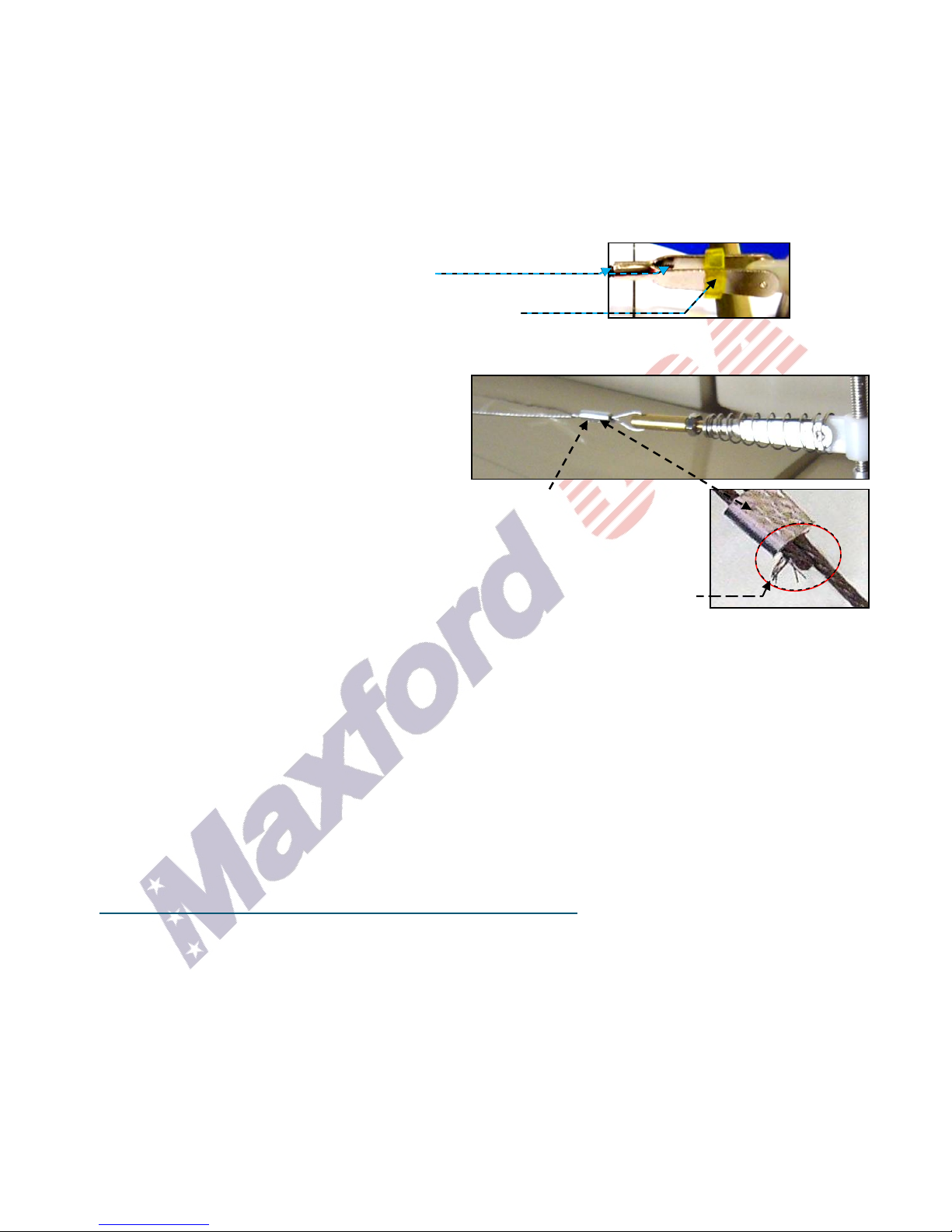
19. After adjusting a clevis, secure the clevis to its threaded rod with
threadlock compound, epoxy, or CA adhesive.
For additional safety, you may hold the clevis closed by adding a
small piece of tubing (not supplied) as shown at the right.
(NOTE: If included with this model, clevises may be made of plastic or metal.)
20. Use crimp tubes to secure wing wires to anchor points and/or to attach pull-pull cables to threaded rods
and clevises as pictured at the right:
a. Slide the crimp tube onto the cable. Pass the
end of the cable through the anchor point or
the hole in the end of the threaded rod.
b. Direct the end of the cable back into and all
the way through the crimp tube.
c. Adjust the cable’s tension, then use pliers to firmly squeeze several places along
the length of the crimp tube to securely crimp the tube onto the cable.
(NOTE: For your safety, after adjustment of any clevis on its pushrod or
threaded rod, we recommend that you apply epoxy or thin CA adhesive to
permanently secure each clevis in position. Also be careful to not leave any
strands of wire poking out from the end of any crimp tube; exposed small steel
strands can be sharp enough to cut or abrade skin!)
21. This model includes some plastic, fiberglass and/or carbon-fiber-reinforced parts. If you ever drill, grind
or sand any such part, wear safety goggles, a particle mask and rubber gloves to guard yourself from eye,
skin and respiratory-tract irritation; never blow into such a part as the dust may blow back into your face.
22. Some products (such as the Nieuport 17, Nieuport 28 and this Gee Bee Y Super Sportster) include a
Maxford USA-designed Max Cowling ‘invisible’ cowl-attachment system consisting of magnets and small
screws to hold the cowl in place. Do not screw these screws all the way in, but leave a narrow gap
between the screw heads and the underlying wood, then test-fit the cowl by pushing it over the screw
heads and twisting it a few degrees. If it won't turn, loosen the screws. If it goes on but is loose, tighten the
screws. To use the included magnets that hold the cowl in position on its mounting screws, glue a magnet
into its opening in the nose. With the first magnet securely in place, position the second magnet so it is
strongly attracted toward the first magnet, then glue the second magnet into its opening in the cowl ring.
23. If you use an electric power system, read “IMPORTANT THINGS TO CONSIDER WHEN INSTALLING AND
OPERATING YOUR MODEL AIRPLANE’S ELECTRIC POWER SYSTEM” on the Maxford USA Website at
http://www.maxfordusa.com/brushlessmotorandcontroller.aspx. Also read any instructions that may be
included with your motor, electronic speed control, battery and charger. Failure to consider and follow
such instructions could result in permanent damage to your model airplane, its electric power system,
their surroundings, and possible bodily harm! If you crash this model airplane, carefully check for any
battery damage. Do NOT attempt to use or recharge a damaged battery.
VIII. LIMITED WARRANTY, LIABILITY WAIVER & RETURN POLICY
Maxford USA guarantees this ARF kit to be free from defects in material and workmanship at the time of
purchase. Our products have been inspected in our factory and are checked again when shipped from our
warehouse. However, Maxford USA cannot directly control the materials you may use or your final
assembly process. Therefore, Maxford USA cannot in any way guarantee the performance of your finished
model airplane. Furthermore, in purchasing this product, you (the buyer or user of this product) exempt,
waive, and relieve Maxford USA from all current or future liability for any personal injury, property
Copyright Maxford USA 2017 Page 5 of 14 S171108
 Loading...