

Maxford USA Fi-156c Instruction Manual

Page 1 of 13 pages
FIESELER Fi-156c STORCH V2.1
V.2-150423
Entire Contents © Copyright 2013 by Maxford USA
I N S T R U C T I O N M A N U A L
(Photo includes the optional ‘Detail Upgrade’ package.)*
Congratulations on your acquisition of Maxford USA’s Fieseler Fi-156c Storch!
The Fi-156 was created as a reconnaissance, liaison and air-ambulance aircraft in 1936 by Dr. Gerhard Fieseler. This unique airplane‟s
legs, struts and windows stuck out everywhere, and its landing gear hung down, looking very much like a long-legged, big-winged bird,
so it was given the nickname “Storch” (the German word for stork).
Virtually nothing about a Storch is streamlined. It was a purpose-built, short takeoff and landing (STOL) aircraft which, with a bit of
headwind, could become airborne in less than 200 feet, and when its low landing speed was combined with a strong headwind, the
Storch appeared to land vertically, and sometimes looked like it was flying backwards.
German Field Marshall Irwin Rommel used his Storch to fly over the front lines as he led the Deutschland Africa Korps.
At least 60 Storchs were captured by the Allies in the course of World War II – which is how Eighth Army British Field Marshal
Bernard „Monty‟ Montgomery obtained a Storch for use as his personal aircraft.
A famous event involving a Storch occurred in September 1943: Hitler sent a commando team to rescue Italian dictator Benito
Mussolini from a mountain stronghold in northern Italy. Led by Otto Skorzeny, the Germans landed a Storch on the 10,000-foot
mountain peak, freed Mussolini, and took off from the prison‟s courtyard. However, the heavily laden craft failed to clear an
outcropping of rock and struck the mountainside in a controlled crash. Nonetheless, the Storch immediately rebounded into the air,
picked up flying speed, and both the Fi-156 Storch and Mussolini successfully escaped.
Unusual for a land-based aircraft, the Storch‟s wings could be folded back in a manner similar to those of a carrier -based fighter,
allowing it to be transported on a trailer or towed behind a vehicle.
SPECIAL FEATURES:
1. After more than a year of design and testing, our original Storch was the first to
offer easy-to-operate folding wings. This new V2 has kept and improved on this
unique design feature.
2. Aileron hinges permit full UP & DOWN travel for the best-possible
roll-control.
3. In-wing mini-servo mounts for independent operation of the
ailerons, flaps and slats, and built-in tray for fuselage-mounted
rudder and elevator mini servos.
4. Included main wheels, scale-like spring-cushioned landing gear and
steerable tail wheel.
5. Windshield and cockpit windows are pretrimmed and preinstalled.
6. Cockpit‟s windowed roof doubles as a battery hatch secured by powerful rare-earth magnets.
7. All airframe assemblies are precovered in Mylar.
8. All required openings are predrilled and/or precut.
9. The fiberglass cowl is prepainted.
V2 IMPROVEMENTS:
Servos not included now leaves servo selection Composite parts are now used in place of
(economy or name brand) to the customer. several parts previously made of wood.
New, improved-design landing gear. Steerable tail wheel‟s linkage is simplified, with more positive control.
*(Optional „Detail Upgrade‟ items include a simulated machine gun, air speed sensor,
light, oil cooler, dashboard and pilot seat – all packaged in a custom-built plywood box.)

Page 2 of 13 pages
TABLE OF CONTENTS
V.2-150423
Entire Contents © Copyright 2013 by Maxford USA
Important safety precautions ............................... 2
Warranty, liability waiver, and return policy ....... 3
Specifications ...................................................... 3
Parts List .............................................................. 3
Assembly instructions .................................... 4
Setup and adjustments .................................. 12
Preparation for transport and field setup ...... 12
Preflight checks ............................................ 12
IMPORTANT SAFETY PRECAUTIONS
TO PROTECT YOUR MODEL, YOURSELF & OTHERS
1. This product should not be considered a toy, but rather a sophisticated, working scale model that functions much like a full-scale
airplane. Because of its performance capabilities, this product, if not assembled and operated correctly, could cause injury to you
or spectators and damage to property. Maxford USA provides you with a high-quality, thoroughly tested model airplane kit with
assembly instructions. However, the quality and capabilities of your finished model airplane depends on how you build it, and
your safety depends on how you use and fly it. Any testing or flying of this model airplane is done entirely at your own risk.
2. Assemble the model airplane according to these instructions. We recommend that you do not alter or modify the model, as doing
so may result in an unsafe or unworkable model. In a few cases the instructions may differ slightly from the photos; in those
instances the written instructions should be considered as correct. If you have any question or concern about these instructions,
before you proceed with assembly of this product, contact us at (562) 529-3988, Monday through Friday, except national holidays,
between 9 AM to 5 PM Pacific time.
3. It is your responsibility to install the R/C system and other components in such a way that this model airplane passes all ground
safety/range tests and that the power system and controls operate smoothly and correctly.
4. Recheck the operation of this model airplane before every flight to ensure that all equipment is still operating correctly and that
the model has remained structurally sound. Also before every flight, check all clevises and other connectors; do not fly without
replacing any that you find damaged or defective.
5. If you are not an experienced R/C pilot or have not flown this type of model before, we recommend that you get the assistance of
an experienced R/C pilot.
6. Throughout the lifetime of this model, use only the Maxford USA-recommended or equivalent electric motor and a new or well-
maintained R/C radio system and the Maxford USA-recommended or equivalent batteries.
7. LITHIUM BATTERY HANDLING & USAGE WARNING!! When using LiPo batteries, read the battery‟s instruction sheet or
on-line information. Failure to follow all instructions could result in permanent damage to the battery, its surroundings, and
bodily harm! If you crash this model airplane, check for battery damage. Do NOT use or charge a damaged Li-Po battery.
ONLY use a Li-Po approved charger.
(NEVER use a NiCd/NiMH charger!)
ALWAYS set the charger‟s output to match the
battery‟s voltage and mAh ratings.
ALWAYS charge through the battery‟s “charge”
connector. (NEVER charge its “discharge” leads.)
ALWAYS charge in a fireproof location.
NEVER place on combustible materials or
leave unattended during charge or discharge.
KEEP BATTERIES OUT OF THE REACH OF CHILDREN
NEVER charge a LiPo battery in excess of 4.2V per cell.
NEVER discharge a LiPo battery below 2.5V per cell.
NEVER allow battery temp. to exceed 150° F (65° C).
NEVER charge at a current greater than 1C (for example,
in the case of a 2100 mAh battery, that‟s 2.1 amps).
NEVER trickle charge.
NEVER disassemble or modify pack wiring in any way
nor puncture any of the battery‟s cells.
8. Read and follow warnings enclosed with your CA adhesive. Apply CA adhesive carefully – Excess drips or runs will leave
unsightly residue and/or „smoky/cloudy areas‟ on nearby surfaces.
9. For your consideration, some customers have told us they always glue some extra triangular-shaped balsa wood to reinforce the
area where the plywood motor box attaches to the firewall on their 300W and larger electric-powered airplanes. (This may be a
good idea!)
10. While this kit has been flight-tested to meet or exceed our rigid performance and reliability standards in normal use, if you plan to
perform any high-stress flying or if you plan to install a larger motor than specified, you (the buyer or user of this product) are
solely responsible for taking any and all necessary steps to reinforce the high-stress points and/or substitute hardware that is more
suitable for such increased stresses.
11. This model may include some fiberglass and carbon-fiber reinforced plastic parts that might require some cutting or sanding.
Fiberglass and carbon-fiber dust may cause eye, skin and respiratory tract irritation. If you ever grind, drill or sand such parts,
always wear safety goggles, a particle mask and rubber gloves; never blow into such a part to remove fiberglass or carbon-fiber
dust, as the dust may blow back into your face.

Page 3 of 13 pages
WARRANTY, LIABILITY WAIVER, AND RETURN POLICY
V.2-150423
Entire Contents © Copyright 2013 by Maxford USA
Maxford USA guarantees this kit to be free of defects in material and workmanship at the time of purchase. All of our products have
been inspected in our factory and are checked again when shipped from our warehouse.
However, Maxford USA cannot directly control the materials you may use nor your final assembly process. Therefore, Maxford USA
can NOT in any way guarantee the performance of your finished model airplane. Furthermore, in purchasing this product, you (the
buyer or user of this product) exempt, waive, and relieve Maxford USA from all current or future liability for any personal injury,
property damage, or wrongful death, and if you (the buyer or user of this product) are involved in any claim or suit, you will not sue
Maxford USA or any of its representatives.
If you do not fully accept the above liability and waiver, you may request a return merchandise authorization number (RMA#) as
explained in item 2, below.
If you think there is a missing part or any shipping damage, please read our after-sales service and return policy as outlined below.
1. Inspect your order upon delivery for any shipping damage or missing part. If you find a problem, you must contact us within 10
days from receipt of your purchase by calling (562) 529-3988, Monday through Friday, except holidays, between the hours of
9 AM and 5 PM Pacific time. During this telephone conversation, and with your support, we will determine how to resolve your
concern. (Note: Maxford USA Li-Po batteries are sold without warranty and are not eligible for return or credit.)
2. To request an RMA#, call (562) 529-3988, Monday through Friday, except holidays, between the hours of 9 AM to 5 PM Pacific
time. If we elect to issue you an RMA#, you must clearly mark this RMA# on the outside of the package. (No return or exchange
will be authorized after 10 days from the date of your receipt of the product; any package delivered to us without a Maxford USA
RMA# is subject to being returned to the sender, as received, with return postage payable upon delivery.) Returned merchandise
must be in its original condition as received from Maxford USA, with no assembly or modification, in the original packing
materials, complete with all manuals and accessories. Return shipping and insurance charges must be prepaid by you, the buyer.
3. Returned merchandise that is accepted by Maxford USA for credit is subject to a 10% to 20% restocking fee; the final amount will
be determined by Maxford USA upon receipt and examination of the returned merchandise.
Return Address:
Maxford USA Distribution, Inc.
15939 Illinois Ave. #B-C
Paramount, CA 90723
(IMPORTANT: If issued by Maxford USA, print the RMA# on the package near the above address.)
SPECIFICATIONS*
Wingspan ............................................ 63 inches
Wing Area ............................. 397 square inches
Motor (not included) .............................................................. Brushless outrunner; 560 Watt; 1,000 RPM/V
(Recommended: Uranus 35425 or equivalent)
Electronic speed control (not included) ........... Brushless, rated for use with a 3S-LiPo battery at 60 Amps.
(Recommended: Uranus 60A or equivalent, with built-in 3A or greater BEC)
Battery (not included) ................................................................ Lithium Polymer, 3S or 4S/2100mAh, 20C
Propeller (not included) ............................... 11x7 (or as recommended by the manufacturer of your motor)
Radio system (not included) ................................................... Minimum of 5 channels with six mini servos
Length .................................................. 40 inches
Flying weight ............................ 2 pounds, 14 oz.
*(All dimensions and weights are approximate; production parts may vary from prototype photos.)
PARTS LIST
1. Items you must supply to complete this model of the Fieseler Fi-156c Storch:
Electric motor, propeller, electronic speed control, LiPo battery and suitable LiPo battery charger.
5- and 30-minute epoxy, hot-melt glue, cyanoacrylate (CA) adhesive, and masking tape.
A few common hand tools such as long-nosed and diagonal or side-cutter pliers, etc.
Radio transmitter, receiver (with a minimum of five channels) and six mini-servos.
Depending on your selection of radio and servos, you may also need four servo extensions and two Y-harness cables
(one set for the ailerons and another set for the flaps & slats).
Page 4 of 13 pages
V.2-150423
Entire Contents © Copyright 2013 by Maxford USA
2. Items included with this model of the Fieseler Fi-156c Storch:
Precovered wing panels with fully functional flaps, slats and ailerons,
with all hinges, horns and linkages.
Precovered vertical and horizontal stabilizers, with rudder and elevator,
precut hinge openings, and all hinges, horns, linkages and pushrods.
Fuselage precovered in yellow and grey Mylar with preinstalled rudder
and elevator pushrod housings.
Composite wing rod and struts and all related hardware, including
screws, bolts and nuts (except those normally supplied with a motor).
Steerable tail-wheel assembly.
Prepainted fiberglass cowl.
Canopy/battery hatch secured by rare-earth magnets.
Preformed spring-cushioned main landing gear and steerable tail wheel.
Adhesive-backed, stick-on marking sheets.
This illustrated instruction manual.
ASSEMBLY INSTRUCTIONS
1. Insert the provided CA hinges into the precut aileron and flap hinge slots in the trailing edge of both wing panels; position each
aileron‟s and flap‟s precut CA hinge slot onto their corresponding CA hinges.
2. Being careful that
the inner end of
each aileron does
not bind against
the outer edge of
its mating flap,
and being careful
to leave enough
clearance between the trailing edge of the wing and the front edge of each aileron and flap so full UP and DOWN travel is
not restricted, permanently secure all aileron and flap hinges with thin CA. (Apply the CA adhesive carefully – Excess drips
or runs will leave unsightly residue and/or „smoky‟ or „cloudy‟ areas on nearby surfaces.)
3. Install the rudder and elevator servos in the fuselage and the aileron and flap
servos and their extensions in both wing panels.
4. Connect the rudder, elevator, aileron and flap servos to your receiver and a
receiver battery. Power ON the radio and use your transmitter to „center‟ the
rudder, elevator and each aileron servo, and position each flap/slat servo to its
UP (level with the bottom of the wing) position. Disconnect the battery and
servos and set the radio system aside.
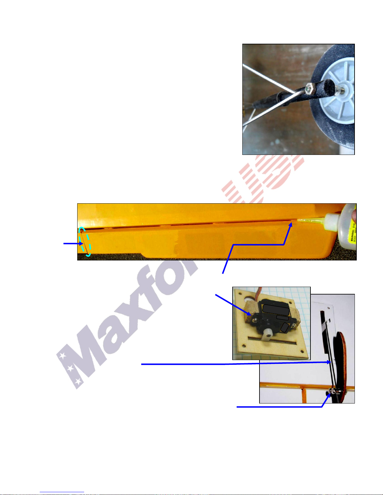
5. Snugly attach quick-connectors to the aileron control horns with the supplied
small nuts. Being careful to not move the aileron servos, connect the aileron
pushrods to each of the aileron servo‟s arms
and insert each aileron pushrod into each aileron control horn‟s quick-connector.
6. Securely attach each aileron control horn into the precut opening in each aileron using
30-minute epoxy.
7. When the epoxy has fully cured, and while holding each aileron in its „neutral‟
position, tighten each of the aileron quick-connectors onto their ailron pushrods.
8. Starting with the left wing panel (and with the ailerons and aileron servos still centered), place the flaps at a „neutral‟ position
(with the bottom surface of each flap even with the bottom of its wing panel), and temporarily hold the flaps in this position by
applying a short length of masking tape across the trailing edges of the ailerons and flaps. Also, apply a bit of masking tape to
hold each slat in its full-UP position (against the wing‟s leading edge).
 Loading...