

Maxford USA F.2B Instruction Manual
F..
Shown with optional simulated WWI pilot, windshield, pilot’s gun sight,
bombs with mounts, electric motor, wood propeller and servos.
F
2
B
B
B
2
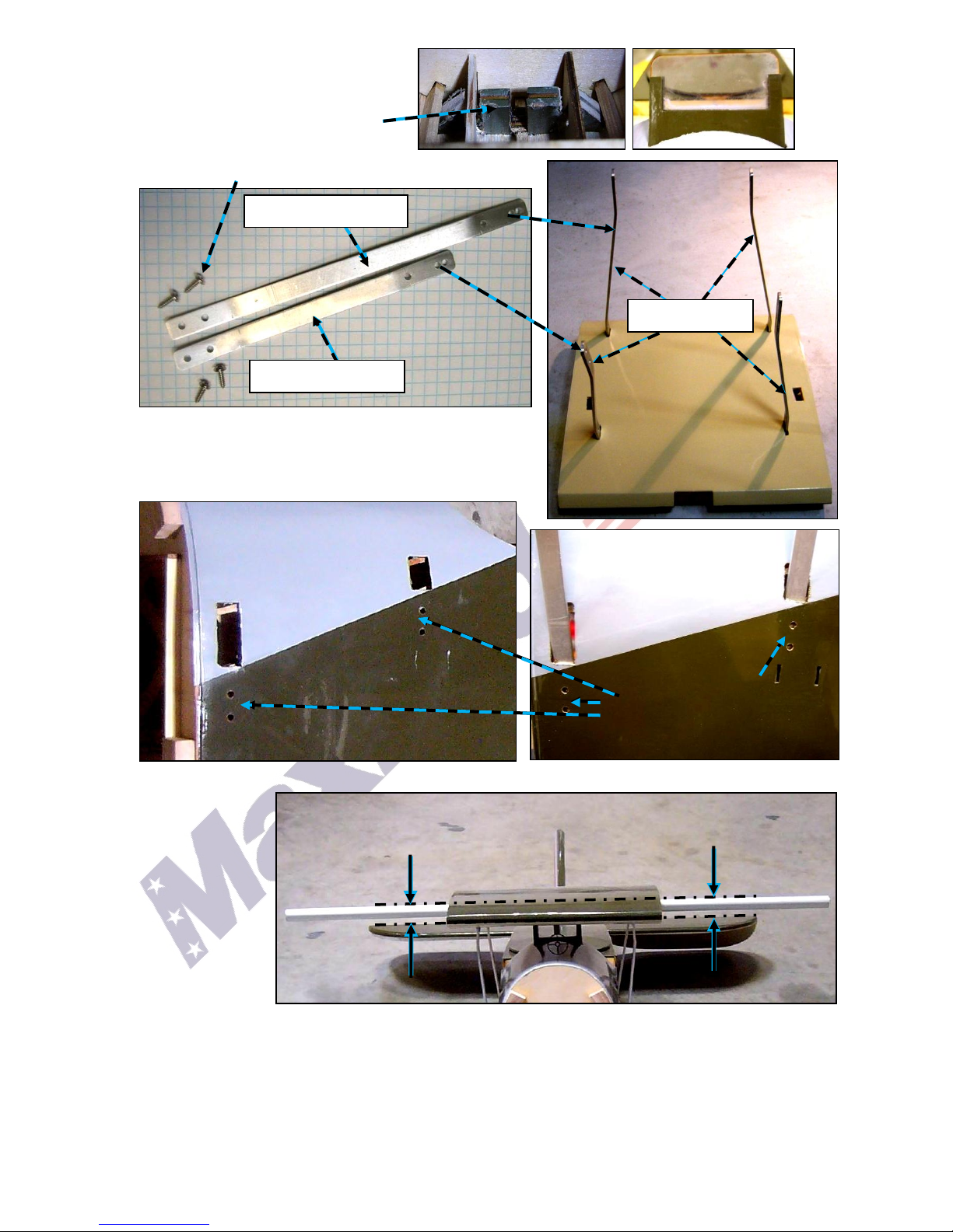
SPORT-SCALE ARF R/C MODEL AIRPLANE
B
RIISS
R
T
T
O
O
L
L
F
F
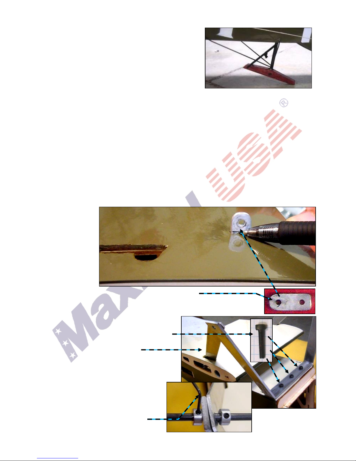
G
IIG
H
H
T
T
E
E
R
R
N SS TT
II N
The F.2B ‘Bristol Fighter’ was a British World War I fighter and reconnaissance biplane designed in
1916 by Frank Barnwell. Although a two-seater, the F.2B proved fast and maneuverable enough to be
flown in combat like a single-seat fighter – and it more than held its own against the opposing singleseat German fighters.
The pilot's fixed forward-firing .303 inch Vickers machine gun was the F.2B’s principal weapon; the
observer's flexible .303 inch Lewis Gun provided an additional "sting in the tail" while the pilot went
after the target. The F.2B could also carry up to 240 pounds of bombs.
The most successful F.2B pilot was Canadian Andrew Edward McKeever, who won all 30 of his
victories in this aircraft.
After the war, many surplus F.2Bs were modified for civilian use. Some were fitted with a canopy to
cover one or two passenger seats in the rear cockpit and renamed the ‘Bristol Tourer,’ which had a
maximum speed of 128 mph.
The Bristol project was first recommend by Mr. Gart Hansford from Dubai UA, one of Maxford USA’s
valued customers. With a 70-inch wingspan, this RC version is approximately 1/6 scale and is
designed to use an electric or glow-power system. It is constructed mainly of laser-cut balsa and light
ply and is finished with a Mylar film covering. To enhance its true-to-scale appearance, this model
includes an articulated tail skid and the rudder and elevators are operated by stranded wire control
cables.
R
R
U
C TT II
U
C
O
O
N
N
M
M
A
A
N
N
U
U
A LL
A
We invite you to enjoy the pride of ownership and the joy of flying this
beautiful ARF sport-scale model of the famous F.2B Bristol Fighter.
Copyright 2014 Maxford USA Page 1 of 24 pages #S140627

TABLE OF CONTENTS:
I.
Important safety precautions ...………….................
2 V.
Special features .……………………….................
5
II.
Warranty, liability waiver & return policy ..........
3 VI.
Assembly instructions ..……….......................
5
III.
Specifications ..……………………………………...........
4 VII.
Setup & adjustments .. ..…………………………
22
IV.
Parts List .….…………………………………………………
4 VIII.
Storage, field setup & preflight checks .....
23
I. SAFETY PRECAUTIONS & ASSEMBLY TIPS
(IMPORTANT – READ THIS SECTION BEFORE YOU BEGIN ASSEMBLY)
1. This product should not be considered a toy, but rather a sophisticated, working model that
functions much like a full-scale airplane. Because of its performance capabilities, this product, if
not assembled and operated correctly, could cause injury to you or spectators and damage to
property. Maxford USA provides you with a high-quality, thoroughly tested model airplane kit with
assembly instructions. However, the quality and capabilities of your finished model airplane
depend on how you assemble it, and your safety depends on how you use and fly it. Any testing or
flying of this model airplane is done entirely at your own risk.
2. Assemble this model airplane according to these instructions. Do not alter or modify the model
beyond the assembly and power-system options covered in these instructions, as doing so may
result in an unsafe or unworkable model. If the instructions differ from the photos, the written
instructions should be considered correct. If you have any question or concern about these
instructions, before you proceed with assembly of this product, contact your dealer or speak to a
Maxford USA customer service representative at 562-529-3988 (Monday through Friday, except
national holidays, 9 AM to 5 PM Pacific Time).
3. While this kit has been flight-tested to meet or exceed our rigid performance and reliability
standards in normal use, if you elect to perform any extremely high-stress flying, such as racing or
advanced aerobatics, or if you install a much larger power system than specified, you (the buyer or
user of this product) are solely responsible for taking any and all necessary steps to reinforce the
high-stress points and/or substitute hardware that is more suitable for such increased stresses.
4. Throughout the lifetime of this model, use only the Maxford USA-recommended power system and
a new or well-maintained radio-control system.
5. It is your responsibility to install the receiver and connect the R/C components in such a way that
this model airplane passes all applicable safety/range tests and that the power system and
controls operate correctly and smoothly.
6. Recheck the operation of this model airplane before every flight to ensure that all equipment is
still operating correctly and that the model has remained structurally sound. Also before every
flight, check all electrical, control and structural connections; do not fly without replacing any that
you find damaged or worn.
7. Before you begin assembly of this model airplane, read all instructions and test-fit each part to
ensure you fully understand the instructions and that no parts are missing, damaged or
unsatisfactory. Temperature and/or humidity differences between the factory, our warehouse and
your home or workshop may dictate the need for slight adjustments to the wings, struts and/or
the vertical or horizontal stabilizer’s mounting surfaces to ensure proper alignment; however, we
recommend you contact us before you attempt any such adjustments.
8. To help ensure the security of your servo connections, we recommend use of optional
Maxford USA servo-extension safety clips.
9. If you are not an experienced R/C pilot or have not flown this type of model before,
we strongly urge you to get assistance from an experienced R/C pilot.
10. You may use 30-minute epoxy to attach critical parts permanently (such as where the horizontal
and vertical stabilizers attach at the end of the fuselage) and apply a threadlock compound to
secure all airframe components from vibration.
Copyright 2014 Maxford USA Page 2 of 24 pages #S140627

11. If you have concern about the security of any factory fabrication procedure(s), you may apply 30-
minute epoxy around the perimeter of such part(s) as an extra safety precaution.
12. After adjusting each clevis, secure the clevis to its threaded rod
with thread-lock compound or CA adhesive.
For additional safety, hold the clevis closed by adding a small
piece of tubing (not supplied) as shown at the right.
13. For your safety, do NOT leave any strands of wire poking out
from the end of any crimp tube. Exposed small steel strands can be
sharp enough to cut or abrade skin!
14. This model may include some plastic, fiberglass and/or carbon-fiber-
reinforced parts. If you drill, grind or sand any such part, always wear
safety goggles, a particle mask and rubber gloves to guard yourself from eye, skin and respiratorytract irritation; never blow into the part as the dust may blow back into your face.
15. Minor production details (such as Mylar or paint colors) may vary. Check the Mylar covering
material’s joints and surfaces; if necessary, carefully use an iron (do NOT set the iron’s
temperature too high) to secure the edges and to tighten any loosened areas. Recheck and
retighten from time to time.
16. If you use an electric power system, read all instructions included with your battery and charger.
Failure to follow all instructions could result in permanent damage to the battery, its surroundings,
and bodily harm! If you crash this model airplane, check whether the battery is damaged. Do NOT
attempt to use or recharge a damaged battery.
II. LIMITED WARRANTY, LIABILITY WAIVER & RETURN POLICY
Maxford USA guarantees this kit to be free from defects in material and workmanship at the time
of purchase. All our products have been inspected in our factory and are checked again when
shipped from our warehouse. However, Maxford USA cannot directly control the materials you
may use or your final assembly process. Therefore, Maxford USA cannot in any way guarantee the
performance of your finished model airplane. Furthermore, in purchasing this product, you (the
buyer or user of this product) exempt, waive, and relieve Maxford USA from all current or future
liability for any personal injury, property damage, or wrongful death, and if you (the buyer or user
of this product) are involved in any claim or suit, you will not sue Maxford USA or any of its
representatives.
If you do not fully accept the above liability and waiver, you may request a return-merchandise
authorization number (RMA#) as explained below in item 2. If you think there is a missing,
damaged or unsatisfactory part, please read our after-sales service and return policy:
1. Inspect your order upon delivery for any missing, damaged or unsatisfactory part(s). If you
believe there is a problem, you must call us at 562-529-3988 (Monday through Friday except
holidays, between the hours of 9 AM and 5 PM Pacific time) before you begin assembly and
within 10 days from receipt of your purchase. During this telephone conversation, and with
your support, we will determine how to resolve your concern.
2. To request a return-merchandise authorization number (RMA#), call 562-529-3988 (Monday
through Friday except holidays, between the hours of 9 AM to 5 PM Pacific Time). If we elect to
issue you an RMA#, you must clearly mark this RMA# on the outside of the package. (No return
or exchange will be authorized after 10 days from the date of your receipt of the product; any
package delivered to us without a Maxford USA RMA# is subject to being returned to the sender,
as received, with return postage payable upon delivery.) Returned merchandise must be in its
original condition as received from Maxford USA, with no assembly or modification, in the
product’s original packing materials, complete with all manuals and accessories. Return
shipping and insurance charges must be prepaid by you, the buyer.
3. Returned merchandise that is accepted by Maxford USA for credit is subject to a 10% to 20%
restocking fee (the final amount will be determined by Maxford USA upon receipt and
examination of the returned merchandise).
Copyright 2014 Maxford USA Page 3 of 24 pages #S140627

Return address:
Radiator-grill hatch secured with magnets.
Prebuilt and covered fuselage, horizontal
stabilizer, elevators, vertical stabilizer,
rudder wings and ailrons, wing center
sectons & interplane struts.
Simulated full-length exhaust pipes.
Prepainted fiberglass cowl.
Scale stick-on markings.
Hardware package.
Adjustable electric motor mounting box.
(Note: Mounting box for a glow engine
is optional.)
Maxford USA
15939 Illinois Avenue, #B-C
Paramount, CA 90723
IMPORTANT: Print the RMA# issued by Maxford USA
on your package near our address.
III. SPECIFICATIONS
Wingspan ......................................................................................................................................................... 70 inches
Wing area ................................................................................................................................... 1,279 square inches
Length ................................................................................................................................................................ 49 inches
ARF weight ..................................................................................................................................................... 7 pounds
Ready-to-fly weight ....................................................... 12 to 14 pounds (depending on power system)
Power system .................................... .90 to 1.20 2-cycle glow engine; U638109 motor, or equivalent
Propeller ... Glow 16x8/10; EP 18x8 or 19x6; or as recommended by the power system’s maker
Radio ..................................................................................................................................... Minimum of 4 channels
Servos ............................................... 3 standard-sized servos (2 for the elevators & 1 for rudder) plus
2, 3, 4 or 5 mini servos as follows: Customer may use 1 mini servo on each of the 4 ailerons, or
customer may use 1 mini servo on each of only 2 of the ailerons; also, 1 additional mini servo
is needed for throttle control if a glow power system is used.
(Dimensions and weights are approximate.)
IV. PARTS LIST
1. Included items
Scale-looking landing-gear struts, wheels and articulated tail skid.
2. Items you must supply to complete this ARF
Epoxy and cyanoacrylate (CA) adhesives and threadlock compound.
Low-tack masking tape and common tools (screwdriver, pliers, etc.).
A four- (or more) channel radio system; and, if customer uses all 4 ailerons, use four 12-inch
servo extensions; two 10-inch servo extensions; two 12-inch Y harnesses; one 6-inch Y harness;
4 mini servos for ailerons, 3 standard-sized servos for rudder and elevators; an electronic speed
control (ESC) for an electric power system or one additional mini-servo plus one 10-inch servo
extension for throttle control of a glow-engine.
Range of 0.90 to 1.20 cubic inch glow engine and compatible fuel tank, or a 1,200-Watt or
greater outer rotor motor with a compatible electronic speed control and battery.
16-inch diameter x 8- or 10-inch pitch propeller, or as specified for your engine or motor.
3. Optional detail-upgrade items you may choose to add
Adjustable engine box for a
glow-engine power system.
Simulated pilot, observer
and 1 or 2 Lewis Guns.
Pilot’s windshield and
gunsight.
Copyright 2014 Maxford USA Page 4 of 24 pages #S140627
V. SPECIAL FEATURES
95% preassembled ARF constructed mainly of jig-
assembled, laser-cut balsa and light plywood, with a
realistic-looking fiberglass cowl and full-length twin
simulated exhaust manifolds.
Steel cables for the wing wires and for the rudder’s
and elevator’s pull-pull cables.
Adjustable-depth motor mounting box, able to
accept a wide range of power system options.
Scale-looking landing gear struts, wheels, articulated tail skid and stick-on scale markings.
Observer’s hatch cover secured by magnets.
Metal skids for wing tip protection.
4 aileron design, but customer can decide to use 2 ailerons on top or bottom set up for only
scale-looking flights (simply tape-over the other 2 ailerons).
Replacement parts and optional upgrade parts are available.
Owner’s choice of electric- or glow-power system.
VI. ASSEMBLY INSTRUCTIONS
A. WING CENTER SECTIONS & LANDING GEAR
NOTE: This model was designed and test-flown with the top and bottom wings set at 0-0 degrees
to each other and to the horizontal stabilizer. If you decide to build in any different incidence
angles (not recommended), you may find it easiest to modify step 20 on page 8, steps 20, 29
and/or 30 on pages 13 and 14 according to your desires.
1. Locate and cut
through any
Mylar covering
the openings
in the top of
the lower
wing’s center
section for the
lower wing’s
4 metal
mounting tabs.
2. Locate the 10 metal mounting tabs shown at the right.
3. Test-fit (DO NOT GLUE at this time) 4 of the metal mounting tabs into the top
of the lower wing’s center section.
4. Mount the landing gear’s main strut using a
3mm hex wrench and threadlock to securely
drive 3 cap head bolts into the preinstalled
blind nuts at the bottom front of the fuselage.
5. Guide the diagonal strut braces
through the openings in the lower wing’s
center section and into their openings in the
bottom of the fuselage.
6. Center the axle through the struts with
4 wheel collars.
7. Leave approx. 2¾ inches (the width of
the wheel plus 2 wheel collars) of axle
outside the struts. Tighten the wheel
collars with a 1.5mm hex wrench.
Copyright 2014 Maxford USA Page 5 of 24 pages #S140627
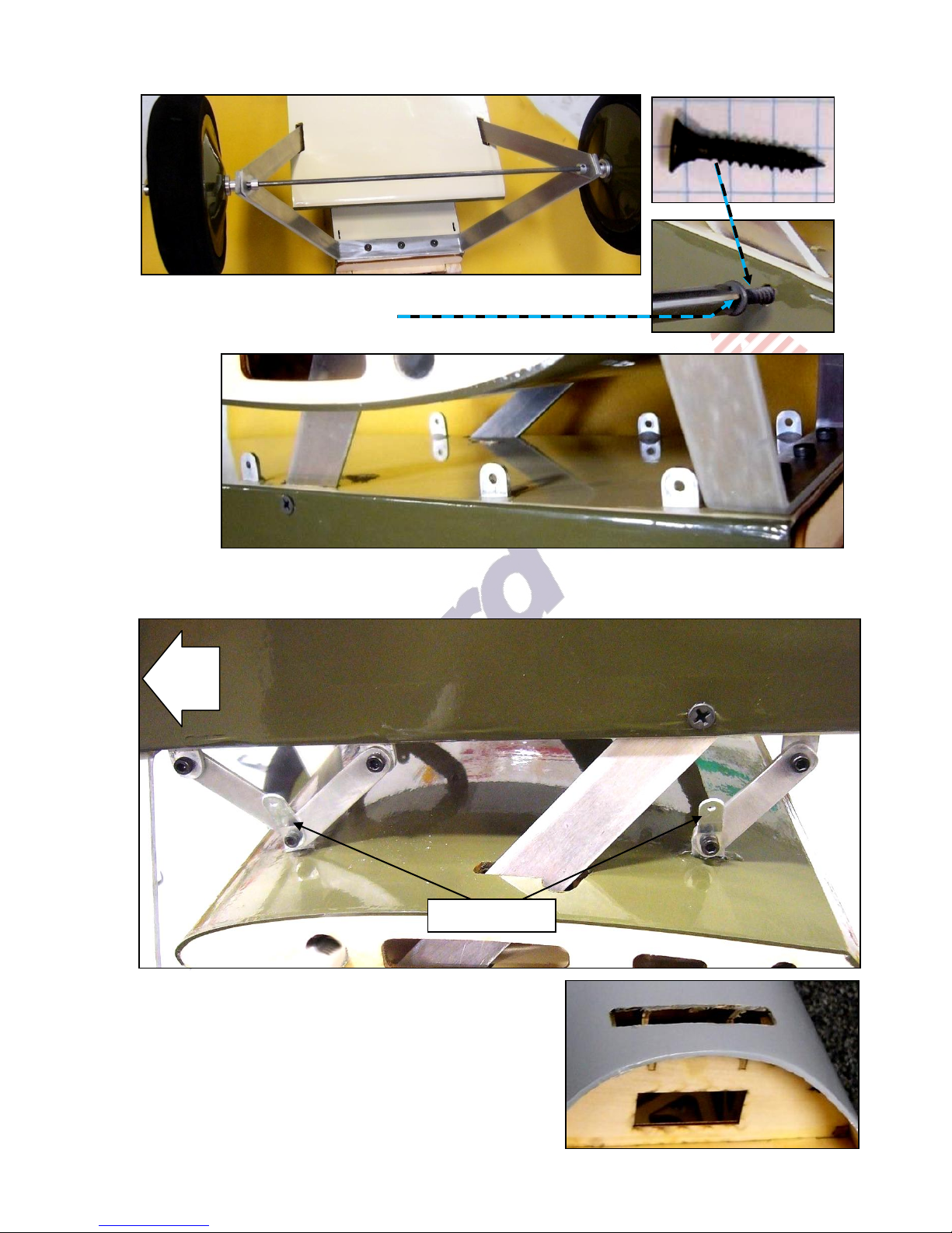
8. Position the wheels on the axle. Secure the wheels onto the axle with 2 additional wheel collars
Nose
Fuselage
Fuselage
Cable anchors
and a 1.5mm hex wrench.
9. Secure the diagonal strut braces into their openings in the fuselage
with screws as shown at the right.
10. Test-fit (DO NOT GLUE at this time) 6 mounting tabs into the fuselage.
11. As shown below, test-fit and loosely attach the lower wing’s mounting brackets, cable anchors,
hex-head bolts and self-locking nuts to the fuselage’s mounting tabs. (NOTE: DO NOT TIGHTEN the
nuts on the bolts and DO NOT GLUE the 4 mounting tabs into the lower wing’s center section.)
12. If you wish to install the optional windshield, cut through
the Mylar covering the slotted opening in front of the
pilot’s cockpit. Slide the windshield’s mounting base
down into its slot.
Copyright 2014 Maxford USA Page 6 of 24 pages #S140627
13. Apply epoxy from inside the nose to
Base of windshield as viewed
from inside the nose
Cabane struts
Rear cabane strut
Front cabane strut
Bottom of
upper wing’s
center section
Cut and remove the
Mylar covering the
rectangular openings
for the cabane struts.
Position the upper wing at the same angle as the horizontal stabilizer
(NOTE: These optional
openings are to secure the
cabanes to the fuselage with
screws instead of epoxy.)
secure the windshield in position.
14. Locate the 4 cabane struts and 8
1 cm (5/16-inch) long wood screws.
15. As shown at the right, test-fit the cabane struts into
their openings in the upper wing’s center section.
16. Test-fit the cabane struts into their openings on each
side of the fuselage.
17. Insert and center a wing rod through the upper wing’s center section.
18. Test-fit the
horizontal
stabilizer into its
slot. Ensure the
horizontal
stabilizer is
centered and at
90 degrees to
the centerline
of the fuselage.
19. As pictured above, visually compare the upper wing’s center section to the horizontal stabilizer. If
either side of the upper wing’s center section looks higher or lower than the horizontal stabilizer,
adjust the depth of the upper wing’s cabane struts in their openings so the upper wing’s center
section aligns with the horizontal stabilizer.
Copyright 2014 Maxford USA Page 7 of 24 pages #S140627

20. Use epoxy to permanently secure the cabane struts into their openings
Approx. 7 5/8 inches (193mm)
Approx. 12 inches (307mm)
in the bottom of the upper wing’s center section and into their pockets in
the fuselage. Before the epoxy has fully cured, the angle of attack of the
upper wing’s center section may be fine-tuned to 0 degrees relative to
the horizontal stabilizer by adjusting the depth of the cabane struts in
their openings. (NOTE: If you prefer, you may drill 1/8-inch holes in the
lower ends of the cabane struts and attach them to the fuselage with
wood screws instead of epoxy.)
21. As shown above, position a 10-inch extension between the root ribs of
the upper wing’s center section. Guide its servo-type lead into the
fuselage through
one of the
cabane-struts’
openings.
22. As shown at the
right, cut the
Mylar covering
the opening for
the tail-skid’s
main post at the
bottom center of
the fuselage.
23. Cut the Mylar
covering the two
small
openings
for the
tail-skid’s supports on each side of the fuselage.
24. Insert the tail skid’s main post into its opening in the fuselage. Look into the fuselage through the
opening in the nose and guide the post all the way to the top of the fuselage as shown below.
25. Insert the tail skid’s 4 wire braces into their
openings on the sides of the fuselage. Apply
a drop of CA adhesive to secure each wire
brace into its opening.
26. Attach the tail skid to its post with a 2mm
bolt and nut. Secure the front of the skid to
the post with a cable tie, rubber bands or a
shoelace (not included). If you will fly from
blacktop or cement, you may protect the skid
by using epoxy to attach a piece of 3/8-inch
wide scrap metal or plastic (not included) to
the bottom surface of the tail skid.
Copyright 2014 Maxford USA Page 8 of 24 pages #S140627
 Loading...