

Maxford USA Curtiss Pusher Instruction Manual
C
Shown in flight with optional simulated pilot,
electric power system, receiver and servos.
C
SPORT-SCALE ARF R/C EP MODEL AIRPLANE
U
U
I N S T R U C T I O N M A N U A L
R
R
TIISSSS
T
P
P
USS
U
H
H
E
E
R
R
The Curtiss Model D was often called the Curtiss Pusher because practically all were built with their
propellers ‘pushing’ from behind their pilots. Much more importantly, since the Wright Brothers’
patents prevented Glenn Curtiss from using wing warping for lateral control, he designed his Model D
with ailerons, which turned out to be the far superior method for achieving lateral control. Early
examples of the Curtiss Pusher had an elevator at the front for pitch control with a horizontal stabilizer
at the rear. The front elevator was ultimately discovered to be unnecessary, resulting in the later
development of the Curtiss “Headless” Pusher.
This sport-scale ARF R/C electric-powered Model D is based on the early-production “Headed”
Curtiss Pusher and is built to approx. 1/9 scale. It is constructed from balsa, plywood and composite
materials and comes prefinished with a two-color Mylar covering scheme.
Two flights of the Headed Curtiss Pusher formed the strong beginnings of a relationship between
Glenn Curtiss and the Navy that remained strong for decades: On November 14, 1910, test pilot
Eugene Ely took off from the USS Birmingham, which was the first time any aircraft successfully took
off and flew from a ship; then, on January 18, 1911, Eugene Ely performed the second precursor to
modern-day Navy aircraft-carrier air operations by landing a Model D aboard the USS Pennsylvania in
the first arrester-cable landing on a ship. In April 1911, the Navy purchased the Model D for use as an
airborne observation platform and the Aeronautical Division of the U.S. Army Signal Corps purchased
the Model D to use as a trainer. Consequently, the Curtiss Model D pusher became among the first
aircraft in the world to be built in any quantity.
We invite you to enjoy the pride of ownership and the joy of flying
this beautiful ARF sport-scale model of the famous Curtiss Pusher.
Copyright 2015 Maxford USA Page 1 of 22 pages #S150422

TABLE OF CONTENTS:
I.
Important safety precautions ...………….................
2 V.
Special features ……………………….................
5
II.
Warranty, liability waiver & return policy ..........
3 VI.
Assembly instructions ..……….......................
5
III.
Specifications ..……………………………………...........
4 VII.
Setup & adjustments ........................................
20
IV.
Parts List .….…………………………………………………
4 VIII.
Storage, field setup & preflight checks ....
22
Clamping bolt
Connector body
Control arm (or mounting tab)
Washer
Mounting nut
I. SAFETY PRECAUTIONS & ASSEMBLY TIPS
(IMPORTANT – READ THIS SECTION BEFORE YOU BEGIN ASSEMBLY)
1. This product should not be considered a toy, but rather a sophisticated, working model that
functions much like a full-scale airplane. Because of its performance capabilities, this product, if
not assembled and operated correctly, could cause injury to you or spectators and damage to
property. Maxford USA provides you with a high-quality, thoroughly tested model airplane kit with
assembly instructions. However, the quality and capabilities of your finished model airplane
depend on how you assemble it, and your safety depends on how you use and fly it. Any testing or
flying of this model airplane is done entirely at your own risk.
2. Assemble this model airplane according to these instructions. Do not alter or modify the model
beyond the assembly and power-system options covered in these instructions, as doing so may
result in an unsafe or unworkable model. If the instructions differ from the photos, the written
instructions should be considered correct. If you have any question or concern about these
instructions, before you proceed with assembly of this product, contact your dealer or speak to a
Maxford USA customer service representative at 562-529-3988 (Monday through Friday, except
national holidays, 9 AM to 5 PM Pacific Time).
3. While this kit has been flight-tested to meet or exceed our rigid performance and reliability
standards in normal use, if you elect to perform any extremely high-stress flying, such as racing or
advanced aerobatics, or if you install a much larger power system than specified, you (the buyer or
user of this product) are solely responsible for taking any and all necessary steps to reinforce the
high-stress points and/or substitute hardware that is more suitable for such increased stresses.
4. Throughout the lifetime of this model, use only the Maxford USA-recommended power system and
a new or well-maintained radio-control system.
5. It is your responsibility to install the receiver and connect the R/C components in such a way that
this model airplane passes all applicable safety/range tests and that the power system and
controls operate correctly and smoothly.
6. Recheck the operation of this model airplane before every flight to ensure that all equipment is
still operating correctly and that the model has remained structurally sound. Also before every
flight, check all electrical, control and structural connections; do not fly without replacing any that
you find damaged or worn.
7. Before you begin assembly of this model airplane, read all instructions and test-fit each part to
ensure you fully understand the instructions and that no parts are missing, damaged or
unsatisfactory. Temperature and/or humidity differences between the factory, our warehouse and
your home or workshop may dictate the need for slight adjustments to the wings, struts and/or
the horizontal stabilizer’s mounting surfaces to ensure proper alignment; we recommend you
contact us before attempting any such adjustments.
8. To help ensure the security of your servo connections, we recommend use of optional
Maxford USA servo-extension safety clips as pictured at the right. (For information
about safety clips see http://www.maxfordusa.com/servoextensionsafetyclip.aspx.)
9. Assemble EZ-Link connectors as shown
at the far right. When applying threadlock compound or CA adhesive, do NOT
glue the EZ-Link connector to the
control arm or mounting tab. Also, be
careful to not let the pushrod rub or
bind against nearby surfaces.
Copyright 2015 Maxford USA Page 2 of 22 pages #S150422

10. We recommend using your radio or a servo tester to center your servos before installation. (You
may learn more about servo testers at http://www.maxfordusa.com/servo.aspx.)
11. String may be supplied to pull your servo’s lead and
servo extension through the wing to your radio receiver;
however, you may find it easier to use masking tape to
temporarily attach the connector to the end of a length of
coat hanger wire, then use the wire to pull the lead and
connector through the airframe as shown at the right.
12. After you have determined each wood-screw’s location, apply thin CA adhesive to harden and
strengthen the wood where the screws are to be inserted.
13. If Mylar hides a CA hinge’s slot, find and open the slot by carefully pressing with a fingernail or
sharp hobby knife.
14. If you are not an experienced ARF assembler or R/C pilot or if you have not flown this type of
model before, we strongly urge you to get assistance from an experienced R/C pilot.
15. You may use epoxy to attach critical parts permanently (such as where the front and rear booms
attach to the upper and lower wing’s center sections and where the horizontal stabilizer attaches
to the tail booms). Apply a threadlock compound to secure all airframe hardware from vibration.
16. If you have concern about the security of any factory fabrication procedure(s), you may apply
extra 5 minute epoxy around the perimeter of such part(s) as a safety precaution.
17. After adjusting each clevis, secure the clevis to its threaded rod
with threadlock compound, epoxy, or CA adhesive.
For additional safety, you may hold the clevis closed by adding a
small piece of tubing (not supplied) as shown at the right.
(NOTE: This model may be packaged with clevises made of either plastic or metal.)
18. Since this model includes some plastic, fiberglass and/or carbon-fiber-reinforced parts, if you drill,
grind or sand any such part, be sure to wear safety goggles, a particle mask and rubber gloves to
guard yourself from eye, skin and respiratory-tract irritation; never blow into the part as the dust
may blow back into your face.
19. Minor production details (such as included hardware items and Mylar or paint colors) may vary.
20. Periodically check the Mylar covering material’s joints and surfaces; if necessary, carefully use an
iron (do NOT set the iron’s temperature too high) to secure the edges and to tighten any loosened
areas.
21. Read all instructions included with your motor, electric speed control, battery and charger. Failure
to follow all instructions could result in permanent damage to these items, their surroundings, and
possible bodily harm! If you crash this model airplane, carefully check whether your battery is
damaged. Do NOT attempt to use or recharge a damaged battery.
II. LIMITED WARRANTY, LIABILITY WAIVER & RETURN POLICY
Maxford USA guarantees this kit to be free from defects in material and workmanship at the time
of purchase. All our products have been inspected in our factory and are checked again when
shipped from our warehouse. However, Maxford USA cannot directly control the materials you
may use or your final assembly process. Therefore, Maxford USA cannot in any way guarantee the
performance of your finished model airplane. Furthermore, in purchasing this product, you (the
buyer or user of this product) exempt, waive, and relieve Maxford USA from all current or future
liability for any personal injury, property damage, or wrongful death, and if you (the buyer or user
of this product) are involved in any claim or suit, you will not sue Maxford USA or any of its
representatives.
If you do not fully accept the above liability and waiver, you may request a return-merchandise
authorization number (RMA#) as explained below in item 2. If you think there is a missing,
damaged or unsatisfactory part, please read our after-sales service and return policy:
1. Inspect your order upon delivery for any missing, damaged or unsatisfactory part(s). If you
believe there is a problem, you must call us at 562-529-3988 (Monday through Friday except
holidays, between the hours of 9 AM and 5 PM Pacific time) before you begin assembly and
Copyright 2015 Maxford USA Page 3 of 22 pages #S150422
within 10 days from receipt of your purchase. During this telephone conversation, and with
Prebuilt and precovered flying surfaces.
Scale-looking tricycle landing-gear.
Composite struts and braces.
Pilot’s seat.
Adjustable motor mounting box.
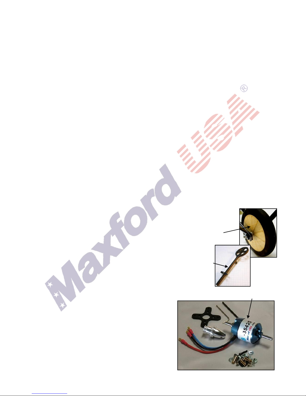
Included standard wheels.
Scale stick-on markings.
Hardware package.
Articulated pilot’s
elevator-control stick.
your support, we will determine how to resolve your concern.
2. To request a return-merchandise authorization number (RMA#), call 562-529-3988 (Monday
through Friday except holidays, between the hours of 9 AM and 5 PM Pacific Time). If we elect
to issue you an RMA#, you must clearly mark this RMA# on the outside of the package. (No
return or exchange will be authorized after 10 days from the date of your receipt of the product;
any package delivered to us without a Maxford USA RMA# is subject to being returned to the
sender, as received, with return postage payable upon delivery.) Returned merchandise must
be in its original condition as received from Maxford USA, with no assembly or modification, in
the product’s original packing materials, complete with all manuals and accessories. Return
shipping and insurance charges must be prepaid by you, the buyer.
3. Returned merchandise that is accepted by Maxford USA for credit is subject to a 10% to 20%
restocking fee (the final amount will be determined by Maxford USA upon receipt and
examination of the returned merchandise).
Return address: Maxford USA
15939 Illinois Avenue, #B-C
Paramount, CA 90723 (Print the RMA# issued by Maxford USA
on your package near our address.)
III. SPECIFICATIONS
Wingspan ......................................................................................................................................................... 50 inches
Length ............................................................................................................................................................ 48.5 inches
Wing area ....................................................................................................................................... 788 square inches
Radio ..................................................................................................................................... Minimum of 4 channels
with 5 mini servos
Flying weight .............................. Around 5.5 to 6 pounds (depending on power and radio systems)
Minimum power ................................................................................................................ 400W brushless motor
Propeller ........................................ 10x6 to 11x7 or as recommended by your power system’s maker
(Dimensions and weights are approximate)
IV. PARTS LIST
1. Included items
2. Items you must supply to complete this ARF
Epoxy and cyanoacrylate (CA) adhesives and threadlock compound.
Common hand tools (screwdriver, pliers, etc.).
Outer rotor motor and electronic speed control (ESC) such as the Maxford USA Uranus 35425
motor and 60A ESC with a 3S or 4S approx. 3,000
mAh LiPo battery, or as recommended for your
motor, and a LiPo battery charger suitable for your
battery.
A four- (or more) channel radio system with five
mini servos; two 24-inch, three 10-inch and two
6-inch servo extensions and two 6-inch Y harnesses.
(Extension lengths may vary, depending on your
installation and choice of radio system components.)
A 10- or 11-inch diameter x 6- or 7-inch pitch
propeller, or as specified for your motor.
Copyright 2015 Maxford USA Page 4 of 22 pages #S150422
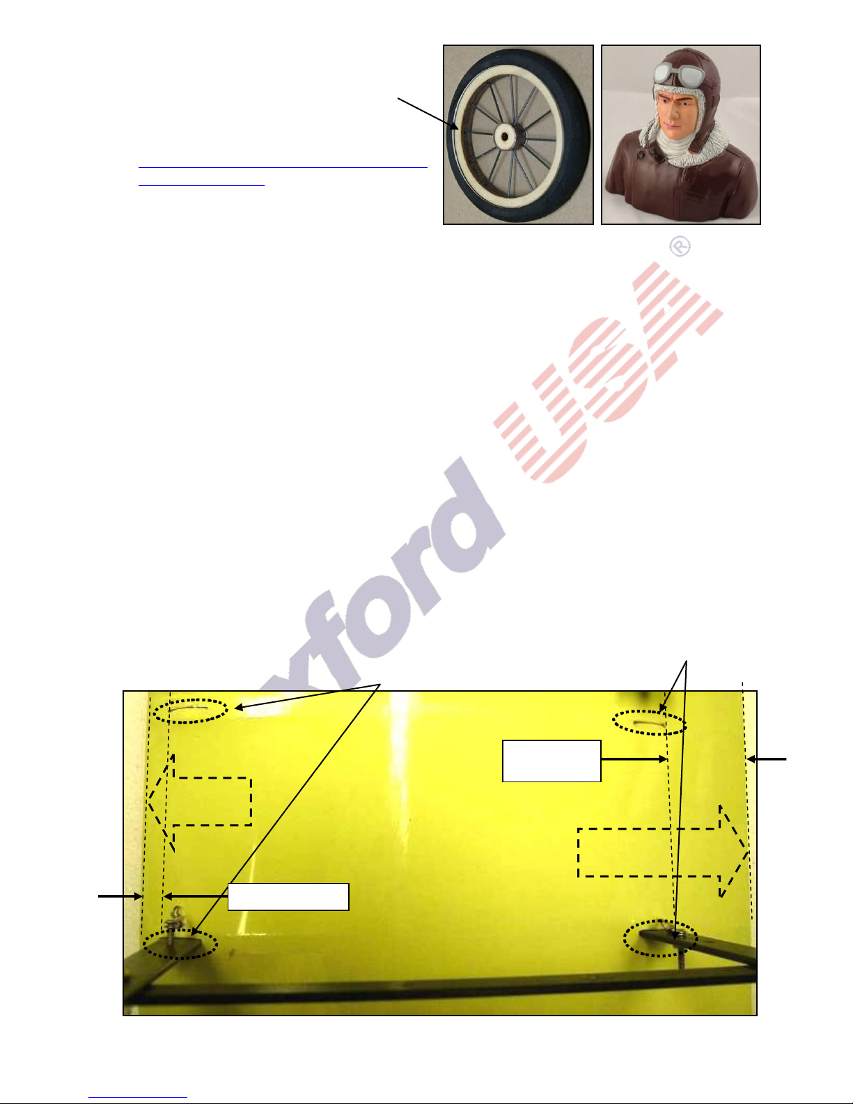
3. Optional items you
Locations of the 4 openings for
the engine-mounting bearers in
the lower wing’s center section.
Approx.
1 1/2-inch
Leading
edge
Trailing
edge
Approx. 1/4-inch
may choose to add
Vintage-style 2 1/2-inch diameter spoked
wheels. (NOTE: This model includes the
standard wheels pictured on instruction
manual pages 1 and 4. Learn about spoked at
http://www.maxfordusa.com/vintagestyle3
spokedwheels.aspx.)
Maxford USA 1/5 scale pilot figure.
Servo extension safety clips.
V. SPECIAL FEATURES
Unique model of this historic pre-World War I aircraft.
Functional front and rear elevators.
Articulated pilot’s control stick.
Scale-looking functional ailerons.
Tricycle landing gear.
Constructed mainly of jig-assembled, laser-cut balsa and light plywood, with composite wing
rods, struts and airframe components.
Precovered scale-looking wings with cream color on top and semi-transparent on the bottom.
Adjustable-depth motor-mounting box, able to accept a wide range of power system options.
Outer wing panels are removable for easy transport and storage.
Black string, swivels and springs are supplied to simulate wing wires and tail-boom bracing.
Replacement parts and optional detail-upgrade items are available.
VI. ASSEMBLY INSTRUCTIONS
1. Locate the openings for the struts and engine-mounting bearers in the bottom of the top wing’s
center section. Set the top wing’s center section aside.
2. Locate the openings for the struts and engine-mounting bearers in the top of the lower wing’s
center section. (NOTE: As shown below, the openings for the engine-mounting bearers are
between 2 extra-wide ribs near the middle of the lower wing’s center section at approx. 1 1/2-
inches in front of the trailing edge and 1/4-inch behind the leading edge.)
Copyright 2015 Maxford USA Page 5 of 22 pages #S150422
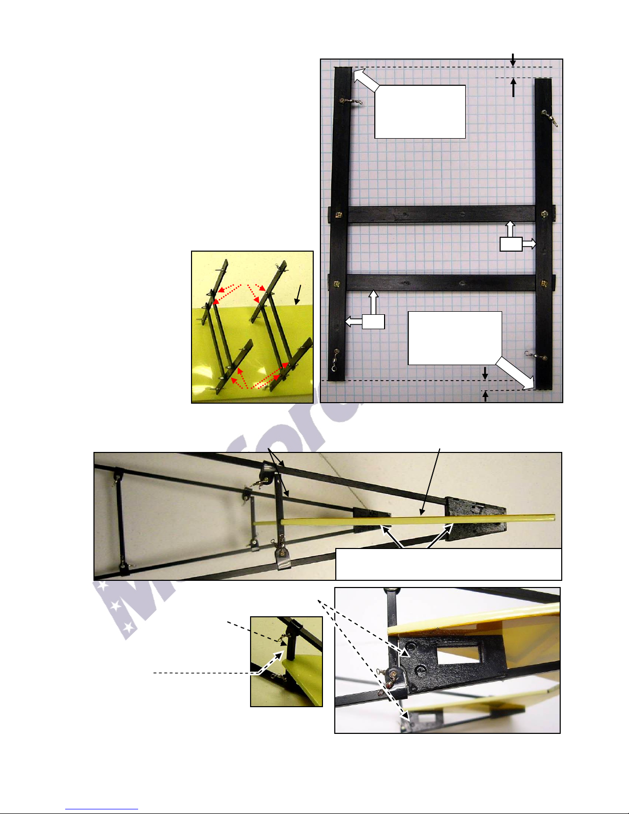
3. To determine how to correctly position the vertical engine-bearer struts in their openings in the
90º
Install the ‘lower’
vertical engine
bearer near the
trailing edge.
90º
Top horizontal engine bearer
Bottom horizontal engine bearer
Bolt
heads
Bolt heads
Trailing
edge
Install the ‘higher’
vertical engine
bearer near the
leading edge.
Front vertical engine bearer Rear vertical engine bearer
NOTE: If necessary, carefully trim or sand the
slotted openings to fit the horizontal stabilizer.
Approx. 1/4-inch
Approx. 1/4-inch
Pictured on
1/4-inch
squares
top of the lower wing’s center section:
a) Position the engine-bearer assemblies with
the horizontal engine bearers at approx. 90
degrees to the vertical engine bearers as
shown at the right. Observe that the end of
one of the vertical engine bearers is about
1/4-inch higher than the other. The ‘higher’
vertical engine bearer will be installed near
the leading edge; the ‘lower’ vertical engine
bearer will be placed near the trailing edge.
b) Observe the bolts that connect the vertical
and horizontal engine bearers: When the
engine bearer assemblies are correctly
positioned, the heads of these bolts will be
facing each other.
4. Being careful to
face the heads of
the bolts toward
each other, test-fit
the ‘HIGHER’ vertical
engine bearers into
the openings near
the leading edge of
the lower wing’s
center section and
the ‘LOWER’ vertical
engine bearers into
the openings near the trailing edge. (NOTE: Do not poke accidently any ‘extra’ holes in the Mylar.)
5. As shown below, test-fit the horizontal stabilizer into the slot at the rear of each tail boom.
(NOTE: The tail boom’s SHORTER struts and the horizontal stabilizer’s TAN side are both at the TOP.)
6. Test-fit a servo tray under each side of the hori-
zontal stabilizer above the lower tail booms.
7. Position the vertical braces
in front of the horizontal
stabilizer into the notched
openings as pictured
at the right.
8. Tighten all the 2mm dia. bolts
into the nuts on both tail boom
assemblies.
Copyright 2015 Maxford USA Page 6 of 22 pages #S150422
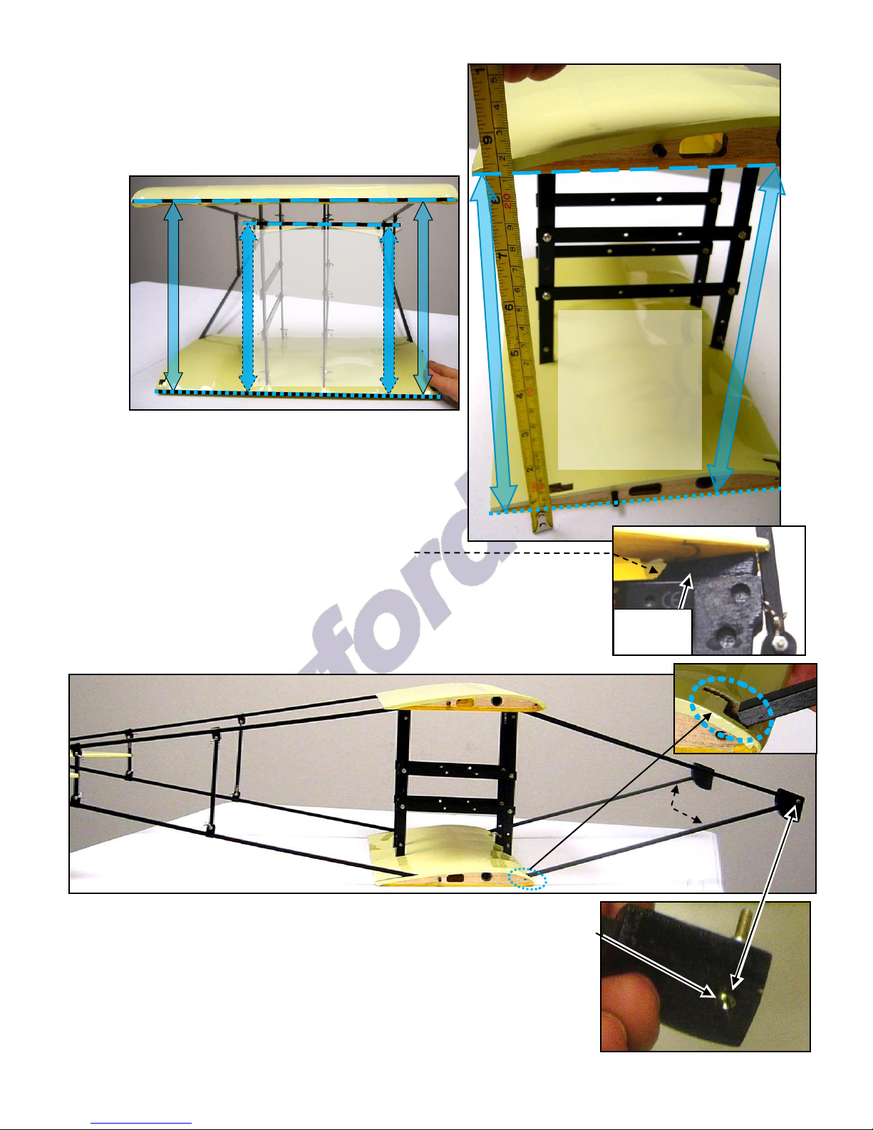
9. Test-fit (DO NOT GLUE at this time) the vertical engine bearers into their openings in the bottom of
Set the top
wing's center
section and the
horizontal
stabilizer
parallel to the
bottom wing's
center section
Optional
spacer
Set the top wing's
center section and
the horizontal
stabilizer to the
same angle of
attack as the
bottom wing's
center section
Rear
booms
Front
booms
SHORTER
struts
the top wing’s center section.
10. Test-fit (DO NOT GLUE at this time) the rear booms
into the openings near the trailing edges of the
top and bottom wing’s center sections.
(REMINDER: The tail boom’s SHORTER struts and
the horizontal stabilizer’s TAN side are at the TOP.)
11. Use the lower wing’s center section as your
reference ensure the upper wing’s center section
and the horizontal stabilizer are parallel and have
the same angle of attack. If necessary, adjust the
depth of the engine bearers and/or the rear
booms in their openings and/or add scrap-wood
spacers (as shown at the right) to fine-tune the
horizontal stabilizer to the center sections.
12. Anchor all four vertical engine-bearer struts into their openings in the
top wing’s center section with glue. (Do NOT apply any glue to the
tail boom’s struts at this time.)
13. Test-fit (DO NOT GLUE at this time) the front booms into their openings
near the leading edges of the top and bottom wing’s center sections.
(NOTE: As shown above, the front booms' shorter struts are installed
at the bottom. As shown at the right, the head of the front elevator’s
hinge-bolt at the front end of each boom faces outward; the threaded
ends of these bolts face each other.)
Copyright 2015 Maxford USA Page 7 of 22 pages #S150422
 Loading...