

Maxford USA Bleriot XI Instruction Manual

Bll
The above photo shows an optional U35425 motor, propeller,
dummy engine and simulated vintage-style spoked wheels.
1 of 16
B
1/6 SPORT-SCALE ARF R/C MODEL AIRPLANE
é
é
rii
r
ott
o
XII
X
N SS TT
II N
On July 25, 1909, French aviator, inventor and engineer Louis Charles Joseph Blériot (pictured at
below center) made the first flight across the English Channel in a heavier-than-air aircraft, a Blériot XI.
This historic achievement not only won Blériot a lasting place in history but assured the future of his
aircraft manufacturing business. The Blériot XI was eventually sold with various wingspans and as
single- and two-seat versions, marketed as trainers, sport/touring, military, and racing/exhibition
aircraft with several different types of engine, including the famous Anzani 3-cylinder fan (or semiradial) engine. Like its predecessor, it was a tractor-configuration monoplane, with a partially covered
box-girder fuselage built from ash with wire cross bracing.
R
R
U
C TT II
U
C
O
O
N
N
M
M
A
A
N
N
U
U
A LL
A
Harriet Quimby (pictured at above right) was America’s first licensed woman pilot. In 1912 she flew
a Blériot XI from England to France across the English Channel. The first Blériot XIs entered military
service in Italy and France in 1910, and a year later, some of those were used in action by Italy in North
Africa – the first use of an aircraft in a war – and in Mexico. The Royal Flying Corps received its first
Blériots in 1912. During the early stages of the First World War, eight French, six British and six Italian
squadrons operated various military versions of the aircraft, mainly in observation duties, but also as
trainers, and in the case of single-seaters, as light bombers with a bomb load of up to 25 kilograms, just
over 55 pounds in traditional American units.
Copyright 2013: Maxford USA Page Blériot XI: S130926

Our radio-controlled Blériot XI is approximately 1/6 scale and suitable for a 3 or 4 channel radio.
I.
Important safety precautions ...…………..........
2 V.
Special features ………………………......
5
II.
Warranty, liability waiver & return policy ...
3 VI.
Assembly instructions ..………............
5
III.
Specifications ..……………………………………....
4 VII.
Setup & adjustments ..…………………
15
IV.
Parts List ….……………………………………………
4 VIII.
Preflight checks …………………………..
16
Addendum ….…… Please see attached – and check at www.MaxfordUSA.com for updates.
2 of 16
Like the original, it features a balanced all-moving vertical rudder and a lifting horizontal tailplane that
is fitted with full-flying elevator surfaces at each end that rotate together on a torque rod extending
through the fixed inner section. The Blériot XI, like many early aircraft, was designed with wingwarping, which may be replicated for some radio-control models but only by a very few experienced
modelers. Wing-warping is not used in this model; instead, to enhance flight performance and safety,
we have added ailerons, which are not scale, but are easy for most beginner and intermediate pilots to
control. Advanced scale pilots who value appearance and are comfortable with slow turns may use tape
to fix the ailerons to the wing and fly with rudder, elevator and throttle only. (Factory-original Mylar is
available to order for covering the ailerons.) We tested a few different versions using different types
and combinations of composite materials to make this Blériot XI a stable sport-aerobatic flyer.
There have been lots of customers, such as Dennis K. Crouch and Wayne Wlocka, who recommended
we develop the Blériot XI. We thank them for their good advice and hope this ARF brings the fun of
flying to all our valued customers.
TABLE OF CONTENTS:
I. SAFETY PRECAUTIONS & ASSEMBLY TIPS:
(IMPORTANT – READ THIS SECTION BEFORE YOU BEGIN ASSEMBLY)
1. This product should not be considered a toy, but rather a sophisticated, working model that
functions much like a full-scale airplane. Because of its performance capabilities, this product, if
not assembled and operated correctly, could cause injury to you or spectators and damage to
property. Maxford USA provides you with a high-quality, thoroughly tested model airplane kit with
assembly instructions. However, the quality and capabilities of your finished model airplane
depend on how you assemble it, and your safety depends on how you use and fly it. Any testing or
flying of this model airplane is done entirely at your own risk.
2. Assemble this model airplane according to these instructions. Do not alter or modify the model
beyond the assembly and power-system options covered in these instructions, as doing so may
result in an unsafe or unworkable model. If the instructions differ from the photos, the written
instructions should be considered correct. If you have any question or concern about these
instructions, before you proceed with assembly of this product, contact your dealer or speak to a
Maxford USA customer service representative at 562-529-3988 (Monday through Friday, except
national holidays, 9 AM to 5 PM Pacific Time).
3. While this kit has been flight-tested to meet or exceed our rigid performance and reliability
standards in normal use, if you elect to perform any extremely high-stress flying, such as racing or
advanced aerobatics, or if you install a much larger power system than specified, you (the buyer or
user of this product) are solely responsible for taking any and all necessary steps to reinforce the
high-stress points and/or substitute hardware that is more suitable for such increased stresses.
4. Throughout the lifetime of this model, use only the Maxford USA-recommended power system and
a new or well-maintained radio-control system.
5. It is your responsibility to install the receiver and connect the R/C components in such a way that
this model airplane passes all applicable safety/range tests and that the power system and
controls operate correctly and smoothly.
6. Recheck the operation of this model airplane before every flight to ensure that all equipment is
still operating correctly and that the model has remained structurally sound. Also before every
flight, check all electrical, control and structural connections; do not fly without replacing any that
you find damaged or worn.
Copyright 2013: Maxford USA Page Blériot XI: S130926

7. Before you begin assembly of this model airplane, read all instructions and test-fit each part to
3 of 16
ensure you fully understand the instructions and that no parts are missing, damaged or
unsatisfactory. (Note: Temperature and/or humidity differences between the factory, our
warehouse and your home or workshop may dictate the need for slight adjustments to the wing,
and/or the vertical or horizontal tail surfaces to ensure proper alignment; however, we recom-
mend you contact us before you attempt any such adjustments.)
8. To help ensure the security of the optional servo connections, we recommend use of
optional Maxford USA servo-extension safety clips.
9. If you are not an experienced R/C pilot or have not flown this type of model before,
we strongly urge you to get assistance from an experienced R/C pilot.
10. You may use 30-minute epoxy to attach critical parts permanently (such as where the elevators
attach to their torque rod) and apply a threadlock compound to secure all airframe components
from vibration.
11. If you have any concern about the security of any factory fabrication procedure(s), you may apply
30-minute epoxy around the perimeter of such part(s) as an extra safety precaution.
12. This model may include some plastic, fiberglass and/or carbon-fiber-reinforced parts. If you drill,
grind or sand any such part, always wear safety goggles, a particle mask and rubber gloves to
guard yourself from eye, skin and respiratory-tract irritation; never blow into the part as the dust
may blow back into your face.
13. Check the Mylar covering material’s joints and surfaces; if necessary, carefully use an iron (do NOT
set the iron’s temperature too high) to secure the edges and to tighten any loosened areas.
Recheck and retighten from time to time.
14. Read all instructions included with your electric power system’s motor, speed control (ESC),
battery and charger. Failure to follow instructions could result in bodily harm and/or permanent
damage to the motor, ESC, battery and surroundings! If you crash this model airplane, check
whether the battery is damaged. Do NOT attempt to use or recharge a damaged battery.
II. LIMITED WARRANTY, LIABILITY WAIVER & RETURN POLICY:
Maxford USA guarantees this kit to be free from defects in material and workmanship at the time
of purchase. All our products have been inspected in our factory and are checked again when
shipped from our warehouse. However, Maxford USA cannot directly control the materials you
may use or your final assembly process. Therefore, Maxford USA cannot in any way guarantee the
performance of your finished model airplane. Furthermore, in purchasing this product, you (the
buyer or user of this product) exempt, waive, and relieve Maxford USA from all current or future
liability for any personal injury, property damage, or wrongful death, and if you (the buyer or user
of this product) are involved in any claim or suit, you will not sue Maxford USA or any of its
representatives.
If you do not fully accept the above liability and waiver, you may request a return-merchandise
authorization number (RMA#) as explained below in item 2. If you think there is a missing,
damaged or unsatisfactory part, please read our after-sales service and return policy:
1. Inspect your order upon delivery for any missing, damaged or unsatisfactory part(s). If you
believe there is a problem, you must call us at 562-529-3988 (Monday through Friday except
holidays, between the hours of 9 AM and 5 PM Pacific time) before you begin assembly and
within 10 days from receipt of your purchase. During this telephone conversation, and with
your support, we will determine how to resolve your concern.
2. To request a return-merchandise authorization number (RMA#), call 562-529-3988 (Monday
through Friday except holidays, between the hours of 9 AM to 5 PM Pacific Time). If we elect to
issue you an RMA#, you must clearly mark this RMA# on the outside of the package. (No return
or exchange will be authorized after 10 days from the date of your receipt of the product; any
package delivered to us without a Maxford USA RMA# is subject to being returned to the sender,
as received, with return postage payable upon delivery.) Returned merchandise must be in its
original condition as received from Maxford USA, with no assembly or modification, in the
Copyright 2013: Maxford USA Page Blériot XI: S130926

product’s original packing materials, complete with all manuals and accessories. Return
Prebuilt and precovered fuselage,
horizontal tailplane, elevators, rudder
and wing.
Included aileron option, complete with all
associated hinges, servo-mounting hatches
and linkages.
Top- and bottom-side wing wire supports.
Scale-looking, shock-absorbing
landing-gear assembly and wheels.
Hardware package, including simulated
wing wires and fuselage boom wires.
This illustrated Instruction Manual.
*
*
Optional seat (only)
4 of 16
shipping and insurance charges must be prepaid by you, the buyer.
3. Returned merchandise that is accepted by Maxford USA for credit is subject to a 10% to 20%
restocking fee (the final amount will be determined by Maxford USA upon receipt and
examination of the returned merchandise).
Return address:
Maxford USA
15939 Illinois Avenue, #B-C
Paramount, CA 90723
IMPORTANT: Print the RMA# issued by Maxford USA
on your package near our address.
III. SPECIFICATIONS:
Wingspan ..................................................................................................................................................... 51 inches
Wing area ................................................................................................................................... 552 square inches
Length ............................................................................................................................................................ 42 inches
ARF weight ................................................................................................................................................. 3 pounds
Ready-to-fly weight ............................................................................................................. 4 pounds 6 ounces
Power system ...... Min. of 400W outrunner motor, 60A ESC, and 4 cell 3,000 mAh Lipo battery
Propeller ....... 11-inch diameter x 6- or 7-inch pitch or larger, per your power system’s maker
Radio ......................................................................... Min. of 3 channels (4 channels if ailerons are used)
Servos ........................................................................... 2 mini servos (4 mini servos if ailerons are used)
(Dimensions and weights are approximate.)
IV. PARTS LIST:
1. Included items
2. Items you must supply
Epoxy and cyanoacrylate (CA) adhesives, threadlock compound and petroleum jelly.
Common hand tools such as screwdrivers, pliers, etc.
Mininum of three-channel radio system with two mini servos. (Using ailerons requires a four-
or-more channel radio plus two additional mini servos and one 6-inch Y harness.)
Minimum of 400-Watt outer rotor motor with compatible electronic speed control, battery and
an 11-inch diameter x 6- or 7-inch pitch propeller or as required by your motor.
3. Optional items you may add
Simulated Anzani 3-cylinder
fan semiradial engine.
Pilot seat and installation set
(only), or pilot seat with a
preglued pilot figure and
installation kit.
Vintage-style spoked wheels.
(ARF comes with solid wood wheels.)
Copyright 2013: Maxford USA Page Blériot XI: S130926
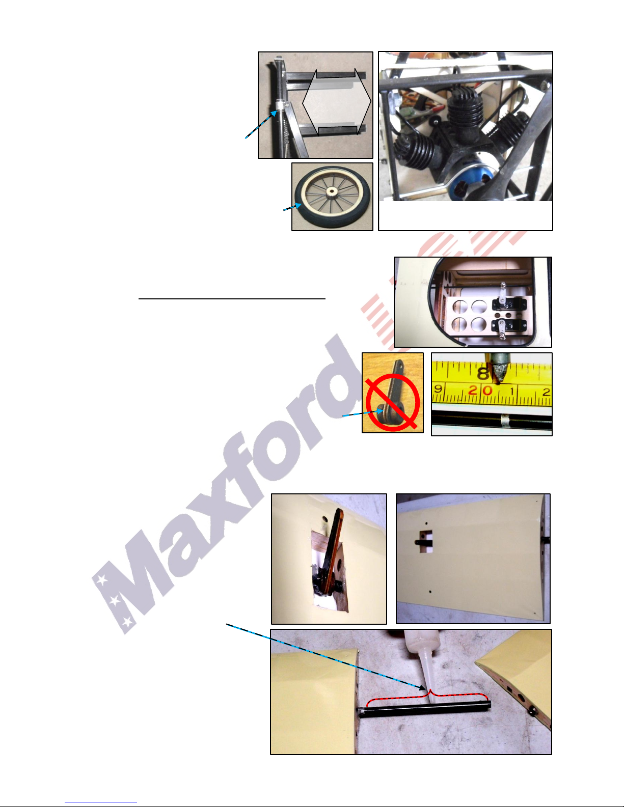
V. SPECIAL FEATURES:
Optional motor, propeller, and
3-cylinder Anzani fan engine
Right end of
the horizontal
tailplane.
Elevator
Rudder
Right-
side
eel
levator
Right-side elevator’s torque rod
Right end of
the horizontal
tailplane.
Adjustable
for motor’s
depth
5 of 16
Unique product – The only ARF
available on the market made
of balsa, plywood and
composite materials.
All-moving rudder and
all-moving twin elevators.
Shock-absorbing landing gear.
Shock-absorbing and steerable
tail wheel.
Customer’s option of scale pilot seat,
pilot and dummy engine.
Optional scale-looking spoked wheels.
VI. ASSEMBLY INSTRUCTIONS:
A. TAIL SECTION:
1. Use your radio or a servo tester to center the elevator and
rudder servos. (You may be interested to learn about servo
testers at http://www.maxfordusa.com/servo.aspx.)
2. Attach EZ-Link connectors to the output arms of the rudder
and elevator servos and use the hardware provided with your
servos to install them in the fuselage.
3. Mark the center of the approx. 16 1/4-inch long by
4mm-diameter composite elevator torque rod. Then,
while inserting the torque rod through its opening in
the horizontal tailplane, position the three wooden
elevator control-horn parts in the center of the torque
rod. (NOTE: Do NOT glue the wooden control-horn
parts together or to the torque rod at this time.)
4. Center the torque rod within the horizontal tailplane. Mark where the torque rod exits each end
of the horizontal tailplane. Help prevent the torque rod from being accidently glued to the
horizontal tailplane by applying petroleum jelly liberally to the torque rod on each side of the
opening for the elevator’s control horn and where the torque rod exits at both ends of the
horizontal tailplane.
5. Test-fit the left- and right-side
elevator panels onto the exposed
ends of the elevator torque rod.
Remove the elevators from the
torque rod.
6. Being careful to not allow any glue
to enter the horizontal tailplane,
apply CA adhesive or epoxy along
the outer length of the right-side
elevator’s torque rod.
Immediately insert this torque rod
into the right-side elevator. Check to
be sure the torque rod remains
centered in the horizontal tailplane
and is able to rotate freely within
the horizontal tailplane.
Copyright 2013: Maxford USA Page Blériot XI: S130926
(NOTE: Do not to get any glue inside the horizontal tailplane. In the event of a minor gluing
Horizontal tailplane
Left
elevator
Right
elevator
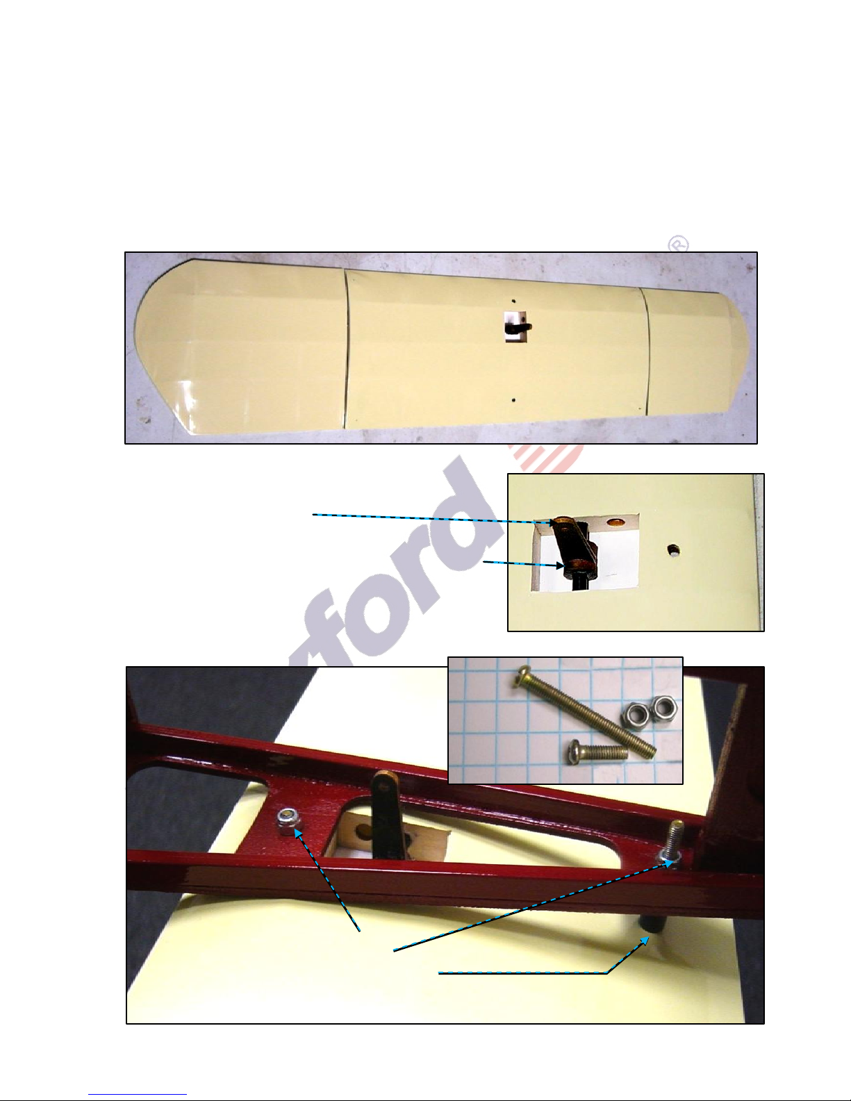
Bolts
and nuts shown
on 1/4-inch
squares
Position the elevator horn at
90 degrees to the flat surface
Approx. 3/8-inch (1 cm) long bolt,
approx. 1 3/16-inch (3 cm) long bolt, matching self-locking nuts and
approx. 1/2-inch (13 mm) tall plastic spacer.
NOTE: Do not shorten the approx. 1 3/16-inch (3 cm) long bolt.
6 of 16
accident, it may help to use a little acetone on the end of a Q-tip as a solvent.)
7. Allow the CA adhesive or epoxy to set fully or cure inside the elevator. When the CA adhesive or
epoxy has set or cured, check that the torque rod remains centered within the tailplane.
8. Being careful not to allow any glue to enter the horizontal tailplane, apply CA adhesive or epoxy
along the outer length of the left-side elevator torque rod. Immediately insert the torque rod fully
into the left-side elevator. Check that the torque rod remains centered within the horizontal
tailplane and able to rotate freely within the horizontal tailplane.
9. As shown below, before the CA adhesive or epoxy has fully set or cured, place the horizontal
tailplane, torque rod and elevator assembly on a flat surface with their flat lower surfaces facing
down and aligned to each other. Allow the CA adhesive or epoxy to set or cure fully.
10. With the horizontal tailplane, torque rod and elevator assembly on a flat surface (with the lower
surfaces facing down as shown above), center the three
elevator control-horn parts on the torque rod and point
the control horn straight up.
11. Firmly press the three wooden elevator control-horn
parts together on the torque rod. Apply thin CA adhesive
to secure the elevator control horn parts to each other
and to the torque rod.
12. Check that the torque rod is still able to rotate freely
within the horizontal tailplane.
13. As shown below, attach the horizontal tailplane beneath the tail booms.
Copyright 2013: Maxford USA Page Blériot XI: S130926
 Loading...