

Maxford USA Albatros D.Va, Albatros D.III Instruction Manual

Allbbaattrrooss
Shown with optional machine guns, Uranus 638109 motor and 18x8 wood propeller
A
11//55 SSPPOORRTT--SSCCAALLEE AARRFF RR//CC MMOODDEELL AAIIRRPPLLAANNE
D..
D
Vaa
V
E
NSS
IIN
T
T
R
R
U
U
C
C
TII
T
O
O
N
N
M
M
A
A
N
N
U
U
A
A
L
L
The Albatros D.III was a single-seat biplane used by the Imperial German Army Air Service and the Austro-Hungarian
Air Service during the First World War. It was heavily armed with twin synchronized, forward-firing 7.92 mm LMG
08/15 machine guns and powered by a 180 hp Mercedes 6-cylinder inline, water-cooled engine (unusual for the time), and
its streamlined radiator, mounted on the top wing, was offset slightly to starboard so that combat damage would not result
in scalding water being released over the pilot. The prototype first flew in August 1916 and was quickly recognized for its
outstanding maneuverability and rate of climb. Like most fighters, the Albatros was prone to spinning. However, its
recovery was straightforward, and German aces including Manfred von Richthofen, Ernst Udet, Erich Löwenhardt,
Kurt Wolff, and Karl Emil Schäfer credited the D.III as being both pleasant and easy to fly.
The Albatros D.Va was the final development of the Albatros D.I family, and the last Albatros fighter to see
operational service. The D.V entered service in May 1917 and, like the D.III before it, immediately began experiencing
structural failures of the lower wing. Indeed, anecdotal evidence suggests that the D.V was even more prone to wing
failures than the D.III. Albatros responded with the D.Va, which featured stronger wing spars, heavier wing ribs, and a
reinforced fuselage.
The Maxford USA 40-inch Albatros D.III was the 1st RC Albatros available in the RC world. This 1/5 sport scale
Albatros D.Va is our 2nd ARF RC Albatros.
We invite you to enjoy the pride of ownership and the joy of flying this
beautiful ARF sport-scale model of the famous Albatros D.Va fighter.
Copyright 2014 Maxford USA Page 1 of 18 #S140424

TABLE OF CONTENTS
I. Safety precautions & assembly tips .................... 2
V. Special features .................................................... 4
II. Warranty, liability waiver & return policy .......... 3
VI. Assembly Instructions ......................................... 5
III. Specifications ...................................................... 4
VII. Setup and adjustments ........................................ 17
IV. Parts list ............................................................... 4
VIII. Storage, field setup & preflight checks .............. 18
I. SAFETY PRECAUTIONS & ASSEMBLY TIPS
(IMPORTANT – READ THIS SECTION BEFORE YOU BEGIN ASSEMBLY)
1. This product should not be considered a toy, but rather a sophisticated, working model that functions much like a full-
scale airplane. Because of its performance capabilities, this product, if not assembled and operated correctly, could
cause injury to you or spectators and damage to property. Maxford USA provides you with a high-quality, thoroughly
tested model airplane kit with assembly instructions. However, the quality and capabilities of your finished model
airplane depend on how you assemble it, and your safety depends on how you use and fly it. Any testing or flying of
this model airplane is done entirely at your own risk.
2. Assemble this model airplane according to these instructions. Do not alter or modify the model beyond the assembly
and power-system options covered in these instructions, as doing so may result in an unsafe or unworkable model. If
the instructions differ from the photos, the written instructions should be considered correct. If you have any question
or concern about these instructions, before you proceed with assembly of this product, contact your dealer or speak to a
Maxford USA customer service representative at 562-529-3988 (Monday through Friday, except national holidays,
9 AM to 5 PM Pacific Time).
3. While this kit has been flight-tested to meet or exceed our rigid performance and reliability standards in normal use, if
you elect to perform any extremely high-stress flying, such as racing or advanced aerobatics, or if you install a much
larger power system than specified, you (the buyer or user of this product) are solely responsible for taking any and all
necessary steps to reinforce the high-stress points and/or substitute hardware that is more suitable for such increased
stresses.
4. Throughout the lifetime of this model, use only the Maxford USA-recommended power system and a new or well-
maintained radio-control system.
5. It is your responsibility to install the receiver and connect the R/C components in such a way that this model airplane
passes all applicable safety/range tests and that the power system and controls operate correctly and smoothly.
6. Recheck the operation of this model airplane before every flight to ensure that all equipment is still operating correctly
and that the model has remained structurally sound. Also before every flight, check all electrical, control and structural
connections; do not fly without replacing any that you find damaged or worn.
7. Before you begin assembly of this model airplane, read all instructions and test-fit each part to ensure you fully
understand the instructions and that no parts are missing, damaged or unsatisfactory. Temperature and/or humidity
differences between the factory, our warehouse and your home or workshop may dictate the need for slight
adjustments to the wings, struts and/or the vertical or horizontal stabilizer‟s mounting surfaces to ensure proper
alignment; however, we recommend you contact us before you attempt any such adjustments.
8. To help ensure the security of your servo connections, we recommend use of optional Maxford USA
servo-extension safety clips.
9. If you are not an experienced R/C pilot or have not flown this type of model before, we strongly urge
you to get assistance from an experienced R/C pilot.
10. You may use 30-minute epoxy to attach critical parts permanently (such as where the horizontal and vertical stabilizers
attach at the end of the fuselage) and apply a threadlock compound to secure all airframe components from vibration.
11. If you have concern about the security of any factory fabrication procedure(s), you may apply 30-minute epoxy around
the perimeter of such part(s) as an extra safety precaution.
12. After adjusting each clevis, secure the clevis to its threaded rod with CA adhesive.
For additional safety, hold the clevis closed by
adding a small piece of tubing (not supplied) as shown at the right.
13. For your safety, do NOT leave any strands of wire poking out from the end of any crimp
tube. Exposed small steel strands can be sharp enough to cut or abrade skin!
Copyright 2014 Maxford USA Page 2 of 18 #S140424

14. This model may include some plastic, fiberglass and/or carbon-fiber-reinforced parts. If you drill, grind or sand any
*
such part, always wear safety goggles, a particle mask and rubber gloves to guard yourself from eye, skin and
respiratory-tract irritation; never blow into the part as the dust may blow back into your face.
15. Minor production details (such as Mylar or paint colors) may vary. Check the Mylar covering material‟s joints and
surfaces; if necessary, carefully use an iron (do NOT set the iron‟s temperature too high) to secure the edges and to
tighten any loosened areas. Recheck and retighten from time to time.
16. If you use an electric power system, read all instructions included with your battery and charger. Failure to follow all
instructions could result in permanent damage to the battery, its surroundings, and bodily harm! If you crash this model
airplane, check whether the battery is damaged. Do NOT attempt to use or recharge a damaged battery.
II. WARRANTY, LIABILITY WAIVER & RETURN POLICY
Maxford USA guarantees this kit to be free from defects in material and workmanship at the time of purchase. All our
products have been inspected in our factory and are checked again when shipped from our warehouse. However,
Maxford USA cannot directly control the materials you may use or your final assembly process. Therefore, Maxford
USA cannot in any way guarantee the performance of your finished model airplane. Furthermore, in purchasing this
product, you (the buyer or user of this product) exempt, waive, and relieve Maxford USA from all current or future
liability for any personal injury, property damage, or wrongful death, and if you (the buyer or user of this product) are
involved in any claim or suit, you will not sue Maxford USA or any of its representatives.
If you do not fully accept the above liability and waiver, you may request a return-merchandise authorization number
(RMA#) as explained below in item 2. If you think there is a missing, damaged or unsatisfactory part, please read our
after-sales service and return policy:
1. Inspect your order upon delivery for any missing, damaged or unsatisfactory part(s). If you believe there is a
problem, you must call us at 562-529-3988 (Monday through Friday except holidays, between the hours of 9 AM
and 5 PM Pacific time) before you begin assembly and within 10 days from receipt of your purchase. During this
telephone conversation, and with your support, we will determine how to resolve your concern.
2. To request a return-merchandise authorization number (RMA#), call 562-529-3988 (Monday through Friday except
holidays, between the hours of 9 AM to 5 PM Pacific Time). If we elect to issue you an RMA#, you must clearly
mark this RMA# on the outside of the package. (No return or exchange will be authorized after 10 days from the
date of your receipt of the product; any package delivered to us without a Maxford USA RMA# is subject to being
returned to the sender, as received, with return postage payable upon delivery.) Returned merchandise must be in its
original condition as received from Maxford USA, with no assembly or modification, in the product‟s original
packing materials, complete with all manuals and accessories. Return shipping and insurance charges must be
prepaid by you, the buyer.
3. Returned merchandise that is accepted by Maxford USA for credit is subject to a 10% to 20% restocking fee (the
final amount will be determined by Maxford USA upon receipt and examination of the returned merchandise).
Return address:
Maxford USA
15939 Illinois Avenue, #B-C
Paramount, CA 90723
IMPORTANT: Print the RMA# issued by Maxford USA
on your package near our address.
Copyright 2014 Maxford USA Page 3 of 18 #S140424

III. SPECIFICATIONS*
Dummy engine.
Prepainted 5 1/2-inch diameter spinner.
Dummy radiator with hoses.
Landing gear and interplane struts.
Nose hatch secured by rare-earth magnets.
Hardware package.
Glow engine power system:
Electric power system:
▫ 0.90 to 1.20 cubic inch 2-cycle engine
▫ Maxford USA U638109 outer rotor motor
▫ Compatible fuel tank and fuel tubing
▫ Maxford USA 100A HV ESC
▫ One additional mini-servo plus one 10-inch servo
extension for throttle control
▫ 10S to 12S LiPo 3,000mAh or greater battery
(or equivalent 1,200-Watt or greater outer rotor
motor with compatible electronic speed control
and battery)
Wingspan ................................................................................................................................................. 70 inches
Wing Area ............................................................................................................................................. 1,241 sq in
Length ...................................................................................................................................................... 57 inches
ARF weight ............................................................................................................................................... 9 pounds
Flying weight ................................................................................................................................. 14 to 15 pounds
Power system ...................................... 0.90 to 1.20 2-stroke glow engine or Maxford USA U638109 motor with
100A HV ESC and 10S to 12S 3,000mAh or greater LiPo battery or equivalent
Propeller ............................ Glow 16x8/10; EP 18x8 or 19x6; or as recommended by the power system‟s maker
Radio ................................................................................................................................. Minimum of 4 channels
Servos ................................... 2 standard-sized servos (rudder & elevator) and 2 mini- or micro-servos (ailerons)
plus an additional standard-sized, mini- or micro-servo for throttle if a glow engine is used
Center of gravity (CG) ......................................................... 4 to 4 1/4-inches behind the top wing‟s leading edge
*(All dimensions and weights are approximate.)
IV. PARTS LIST
A. SUPPLIED ITEMS:
Prebuilt and Mylar-covered fuselage, upper and lower wing panels, top wing‟s center section and ailerons,
horizontal stabilizer, elevator, vertical stabilizer, rudder, and fin (with articulated, spring-loaded tail skid).
B. ITEMS YOU MUST SUPPLY TO COMPLETE THIS ARF:
Epoxy and cyanoacrylate (CA) adhesives and threadlock compound.
Low-tack masking tape and common tools (screwdriver, pliers, etc.).
A 4- (or more) channel radio system; three 6-inch servo extensions, one 12-inch Y harness and two mini-
servos for ailerons; and two standard-sized servos for rudder and elevator.
18- or 19-inch diameter x 8- or 10-inch pitch propeller, or as specified for your engine or motor.
C. OPTIONAL DETAIL-UPGRADE ITEMS YOU MAY CHOOSE TO ADD:
Simulated pilot and machine guns.
V. SPECIAL FEATURES
True-to-scale large-sized spinner,
radiator, dummy engine, windshield
and optional guns.
Shock-absorbing tail skid.
Copyright 2014 Maxford USA Page 4 of 18 #S140424

Easy-remove wings
with Maxlok system.
Each aileron separately
operated by its own, inwing servo.
Pull-pull elevator.
Pushrod-controlled
rudder.
Owner‟s choice of electric- or glow-power system.
Included scale-looking stick-on markings.
The bottom hatch is strongly secured by 12 rare-earth
magnets.
Replacement parts, optional simulated-machine guns and
additional scale upgrades are available.
VI. ASSEMBLY INSTRUCTIONS
A. LANDING GEAR:
1. Test-fit the landing gear‟s cross-pieces into the slots
in the fuselage (one behind the trailing edge of the
lower wing and the other behind the firewall under
the hatch).
2. As shown at the right, attach the front of the main
landing-gear strut to the fuselage using the 2 shorter
metal brackets, a total of four 3/4-inch (15mm) long
wood screws and the predrilled guide holes.
3. Slide the landing-gear strut‟s rear cross-piece into its
slot, position the spacer on top of the strut, and use
the 2 longer metal brackets, a total of four 3/4-inch
(15mm) long wood screws and the predrilled guide holes to attach the landing gear to the fuselage as shown at
the right.
4. Position a wheel collar, wheel, and a 2nd wheel
collar on the end of each axle.
5. Press the inner wheel collars firmly against the
landing-gear struts and tighten the set screws to
secure these 2 inner wheel collars to the axle.
6. Position both outer wheel collars so each wheel
turns freely on its axle, then tighten the set
screws to securely attach these 2 outer wheel
collars to the axle.
Copyright 2014 Maxford USA Page 5 of 18 #S140424
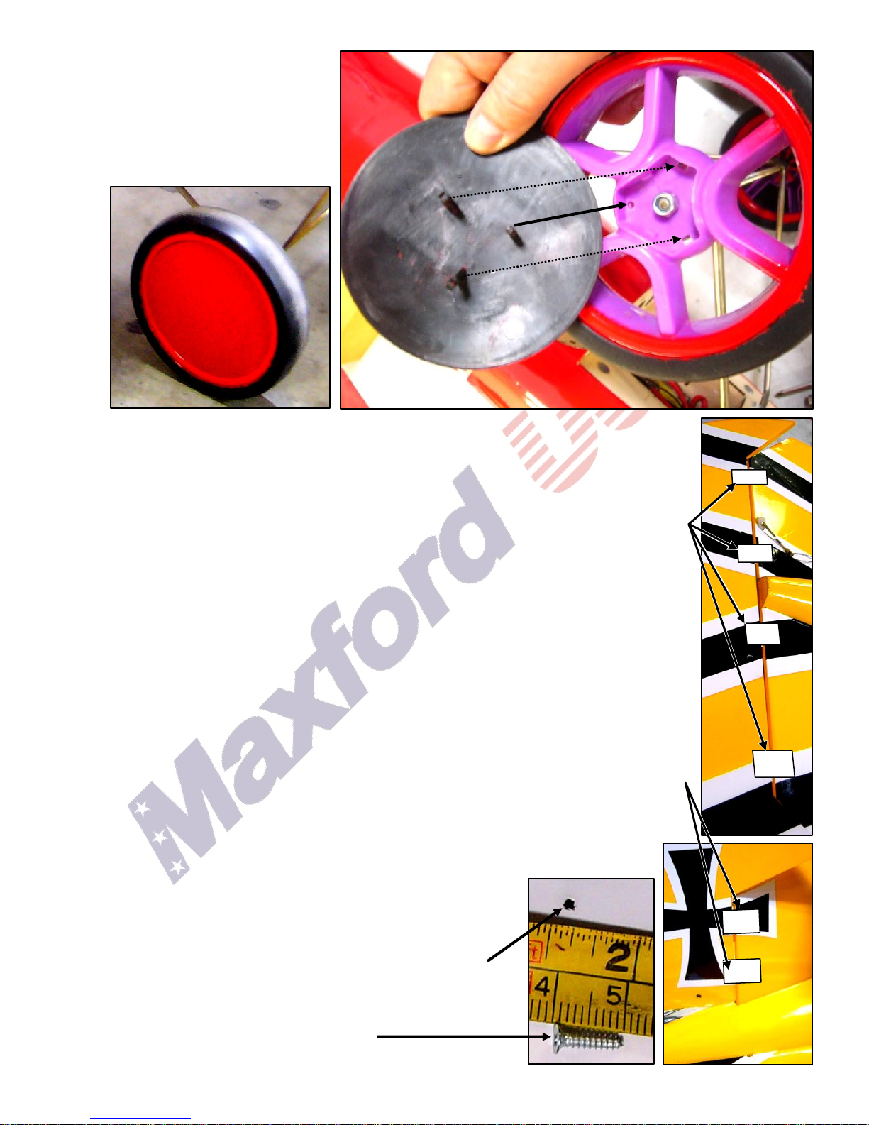
7. As shown at the right, align each
Typical
guide-hole
NOTE: Colors may vary.
hubcap‟s round post to the round
opening in the hub of each wheel.
Press the retaining clip at the end
of the two remaining posts into
their rectangular openings in the
hubs.
B. TAIL SECTION:
1. Slide the lower wing‟s carbon-fiber rod midway through its opening in the fuselage.
2. Test-fit both halves of the horizontal stabilizer (with the white sides toward the bottom of
the fuselage) into the slots in the sides of the fuselage. Align the horizontal stabilizer so it
appears parallel to the carbon-fiber rod.
3. If necessary, cut through any excess Mylar covering the CA hinge slots and use 4 CA hinges
to temporarily fit the elevator to the horizontal stabilizer. Align the black and white trim on
the elevator and horizontal stabilizer. Remove the elevator from the horizontal stabilizer.
4. Ensure good wood-to-wood glue joints by removing any excess Mylar from where each half
of the horizontal stabilizer slides into its slot.
5. Use epoxy to secure both halves of the horizontal stabilizer into the slots.
6. Before the epoxy fully cures, use 4 CA hinges and CA adhesive to permanently attach the
elevator to the horizontal stabilizer and make any final adjustment to the position of the
horizontal stabilizer.
7. Test-fit the upper vertical fin into its slot at the top of the fuselage. Align the upper vertical
fin at 90 degrees to the horizontal stabilizer.
8. Ensure a good wood-to-wood glue joint by removing any excess Mylar that enters the slot.
Secure the upper vertical fin in its slot with epoxy.
9. If necessary, cut through any excess Mylar covering the CA hinge slots and use 2 CA hinges
and CA adhesive to permanently attach the rudder to the upper vertical fin.
10. Test-fit the lower vertical fin (with preattached tail-skid assembly) into its slot in the bottom
of the fuselage. Align the lower fin at 90 degrees to the horizontal stabilizer.
11. Ensure a good wood-to-wood glue joint by removing any excess Mylar from the lower
fin that enters its slot.
12. Secure the lower fin in its slot with epoxy.
C. TOP WING’S CENTER SECTION & NOSE:
1. Slide 2 carbon-fiber rods midway through their
openings in the top wing‟s
center section.
2. Use the guide holes to attach the lower radiator
assembly to the bottom of the top wing‟s center
section with four 3/8-inch (10mm) screws.
Copyright 2014 Maxford USA Page 6 of 18 #S140424
 Loading...