

Page 1
Maxey Moverley Limited, 6 Broad Ground Road, Lakeside, Redditch, Worcestershire, B98 8YP
Web: www.cctvrepairs.com ● Email: enquiries@maxeymoverley.com
Tel: 01527 522299 ● Fax: 01527 522588
Issue 1.1
| Page 1
Quick Reference Guide
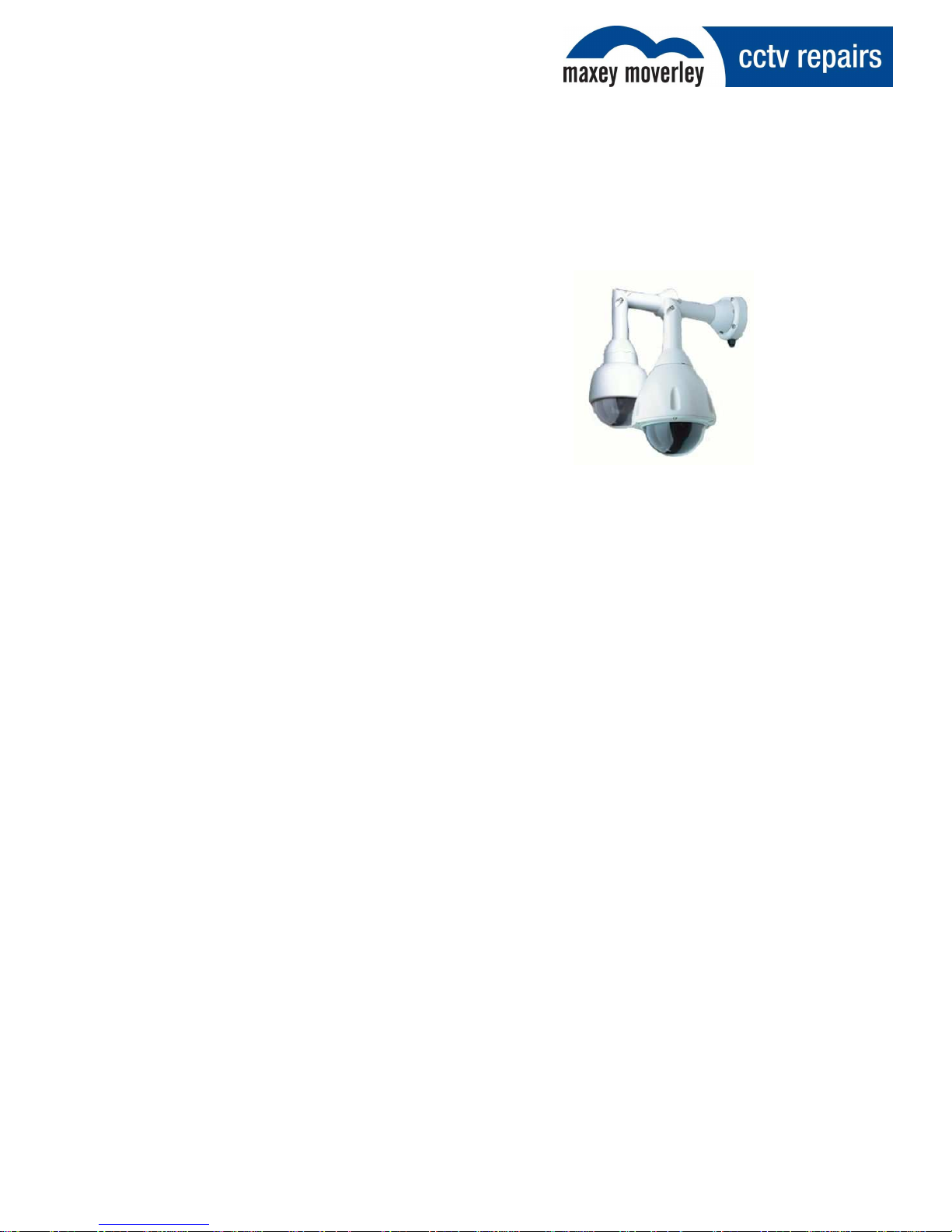
Dedicated Micros 2060
Dedicated Micros 2060
Quick Reference Guide
Contents
1. INTRODUCTION 2
1.1 Description 2
2. CONNECTIONS 2
3. ADDRESS SWITCHES 3
3.1 Address Chart 3
4. CONTROLS 5
4.1 RS485 Configuration 5
4.2 Twisted Pair Configuration 5
4.3 Up the Co-ax Configuration 5
5. TECHNICAL SUPPORT HELPLINE 6
6. REVISION HISTORY 7
Page 2

Maxey Moverley Limited, 6 Broad Ground Road, Lakeside, Redditch, Worcestershire, B98 8YP
Web: www.cctvrepairs.com ● Email: enquiries@maxeymoverley.com
Tel: 01527 522299 ● Fax: 01527 522588
Date: 28/03/2013
| Page 2
Quick Reference Guide
Dedicated Micros 2060
1. Introduction
This guide provided by Maxey Moverley Limited contains programming instructions to aid onsite
engineers in tackling common problems when installing Dedicated Micros 2060 cameras.
This information has been compiled from publicly available documentation in conjunction with the
observations of Maxey Moverley Limited.
1.1. Description
The Dedicated Micros 2060 camera is a precision unit, offering a wide variable speed range, together
with a large pre-set memory for positions, tours and alarm responses.
The Dedicated Micros 2060 Camera has a number of features which can be selected by the System
Supervisor when the dome is installed. Any of these can be altered subsequently, or cancelled
altogether, to give the best operational responses for any particular application. They are invoked or
cancelled through on-screen menu structures and the settings are then retained in non-volatile
memory so that they are not affected by a loss of power.
2. Connections
The type 2060 external connections are via an IP66 Amphenol connector with 3 metre composite
cable flying lead comprising co-ax, power pair & RS485 pair. This lead should be connected to the
boxed P.S.U. supplied with the dome (can be extended to 30 metres max. in length) The connections
are as follows:
Red Wire 24 V AC live
Blue Wire 24 V AC neutral
Yellow Wire R.S. 485 ‘A’
Green Wire R.S. 485 ‘B’
Coax Screen BNC screen
Coax Signal BNC centre pin
The co-ax and power wires are always connected, the RS 485 wires are only connected when an
external protocol converter is fitted or an RS485 controller is being used.
Page 3

Maxey Moverley Limited, 6 Broad Ground Road, Lakeside, Redditch, Worcestershire, B98 8YP
Web: www.cctvrepairs.com ● Email: enquiries@maxeymoverley.com
Tel: 01527 522299 ● Fax: 01527 522588
Date: 28/03/2013
| Page 3
Quick Reference Guide
Dedicated Micros 2060
3. Address Switches
3.1 Address Chart
0 1 2 3 4 5 6 7 8 9 A B C D E F
0 0 1 2 3 4 5 6 7 8 9 10 11 12 13 14 15
1 16 17 18 19 20 21 22 23 24 25 26 27 28 29 30 31
2 32 33 34 35 36 37 38 39 40 41 42 43 44 45 46 47
3 48 49 50 51 52 53 54 55 56 57 58 59 60 61 62 63
4 64 65 66 67 68 69 70 71 72 73 74 75 76 77 78 79
5 80 81 82 83 84 85 86 87 88 89 90 91 92 93 94 95
6 96 97 98 99 100 101 102 103 104 105 106 107 108 109 110 111
7 112 113 114 115 116 117 118 119 120 121 122 123 124 125 126 127
8 128 129 130 131 132 133 134 135 136 137 138 139 140 141 142 143
9 144 145 146 147 148 149 150 151 152 153 154 155 156 157 158 159
A 160 161 162 163 164 165 166 167 168 169 170 171 172 173 174 175
B 176 177 178 179 180 181 182 183 184 185 186 187 188 189 190 191
C 192 193 194 195 196 197 198 199 200 201 202 203 204 205 206 207
D 208 209 210 211 212 213 214 215 216 217 218 219 220 221 222 223
E 224 225 226 227 228 229 230 231 232 233 234 235 236 237 238 239
F 240 241 242 243 244 245 246 247 248 249 250 251 252 253 254 255
Yellow Rotary Address Switch
Blue Rotary Address Switch
Page 4

Maxey Moverley Limited, 6 Broad Ground Road, Lakeside, Redditch, Worcestershire, B98 8YP
Web: www.cctvrepairs.com ● Email: enquiries@maxeymoverley.com
Tel: 01527 522299 ● Fax: 01527 522588
Date: 28/03/2013
| Page 4
Quick Reference Guide
Dedicated Micros 2060
The type 2060 can be controlled via RS 485 commands or ‘up the co-ax’.
With RS 485 control each dome has to individually addressed using the Blue and Yellow rotary
address switches following the address chart on the previous page. For ‘up the co-ax’ control, using
the built in protocol converter, the same address switches are used to select the protocol format for
the controller being used e.g.
BAX AC PANEL Blue. F Yellow. C = 252
For: Baxall a.c. controllers
DEN PANEL Blue.F Yellow. D = 253
For: Dedicated Micros, BBV & DM Sprite controllers
BAX DC PANEL Blue.F Yellow. D = 254
For: Baxall d.c. controllers
For ‘up the co-ax’ control using external protocol converters like the drx 100 or DAX-DEN the address
swtiches should be set to Blue.0 Yellow.1 = 1.
To access the address swtiches remove the outer hemisphere and inner shroud as shown in A & B.
Picture C shows the location. This operation should be carried out in an office type environment to
avoid ingress of moist air.
Page 5

Maxey Moverley Limited, 6 Broad Ground Road, Lakeside, Redditch, Worcestershire, B98 8YP
Web: www.cctvrepairs.com ● Email: enquiries@maxeymoverley.com
Tel: 01527 522299 ● Fax: 01527 522588
Date: 28/03/2013
| Page 5
Quick Reference Guide
Dedicated Micros 2060
4. Controls
The Dedicated Micros 2060 dome can be controlled by one of three methods.
4.1 RS485 Configuration
4.2 Twisted Pair Configuration
4.3 Up the Co-ax Configuration
Page 6

Maxey Moverley Limited, 6 Broad Ground Road, Lakeside, Redditch, Worcestershire, B98 8YP
Web: www.cctvrepairs.com ● Email: enquiries@maxeymoverley.com
Tel: 01527 522299 ● Fax: 01527 522588
Date: 28/03/2013
| Page 6
Quick Reference Guide
Dedicated Micros 2060
5. Technical Support Helpline
For help and guidance with installation issues, that are not covered within this guide please contact
our dedicated customer technical helpline on 01527 522299 and speak to one of our specially
trained technicians will who will be happy to assist you.
Page 7

Maxey Moverley Limited, 6 Broad Ground Road, Lakeside, Redditch, Worcestershire, B98 8YP
Web: www.cctvrepairs.com ● Email: enquiries@maxeymoverley.com
Tel: 01527 522299 ● Fax: 01527 522588
Date: 28/03/2013
| Page 7
Quick Reference Guide
Dedicated Micros 2060
6. Revision History
Revision
Date
Author
Amendments
Comments
1 24/04/2013 DS First Draft Issued for internal review
1.1 14/05/2013 DS Agreed format/content Issued for distribution
 Loading...