

Page 1

1
Lecture Capture Station
MA-XL1
User’s Manual (detailed)
Operating Guide
Thank you for purchasing this Lecture Capture Station.
Please read this manual thoroughly before using the product.
Our website: Please see the attached sheet
WARNING
• Before using this product, please read all manuals for this product. Be sure to read “Safety Guide”
first. After reading them, store them in a safe place for future reference.
About this manual
Various symbols are used in this manual. The meanings of these symbols are described below.
WARNING
This symbol indicates information that, if ignored, could possibly result in personal
injury or even death due to incorrect handling.
CAUTION
This symbol indicates information that, if ignored, could possibly result in personal
injury or physical damage due to incorrect handling.
NOTICE
This entry notices of fear of causing trouble.
Please refer to the pages written following this symbol.
Do not open
CAUTION
RISK OF ELECTRIC SHOCK
DO NOT OPEN
The lightning flash with an
arrowhead within a triangle is
intended to tell the user that
inside this product may cause
risk of electrical shock to
persons.
CAUTION / TO REDUCE THE RISK OF ELECTRIC SHOCK
DO NOT REMOVE COVER(OR BACK)
NO USER-SERVICEABLE PARTS INSIDE
REFER SERVICING TO QUALIFIED SERVICE PERSONNEL
The exclamation point within a
triangle is intended to tell the
user that important operating
and/or servicing instructions are
included in the technical
documentation for this
equipment.
[NOTE]
• The information in this manual is subject to change without notice.
• The illustrations in this manual are for illustrative purposes. They may differ slightly from your
product.
• The manufacturer assumes no responsibility for any errors that may appear in this manual.
• The reproduction, transfer or copy of all or any part of this document is not permitted without
express written consent.
NOTICE
When recovering the product for repairing or replacing the product, the data, account ID,
account password, and setting data saved in the HDD will be deleted immediately after
recovery, for the purpose of protecting personal information. Since it is impossible to restore
the data saved in the HDD, be sure to back up the necessary data and settings.
If we recover the product, you are deemed to have agreed to the above.
Page 2

2
Trademark acknowledgment
• Microsoft® and Windows®, Internet Explorer®, PowerPoint® are registered trademarks of Microsoft
Corporation in the U.S. and/or other countries.
• Mac®, Mac OS® and OS X® are registered trademarks of Apple Inc. in the U.S. and/or other countries.
• VESA and DDC are trademarks of the Video Electronics Standard Association.
•
The Adopted Trademarks HDMI, HDMI High-Definition Multimedia
Interface, and the HDMI Logo are trademarks or registered trademarks of
HDMI Licensing Administrator, Inc. in the United States and other
countries.
• Trademark PJLink is a trademark applied for trademark rights in Japan, the
United States of America and other countries and areas.
• The Bluetooth® word mark and logos are registered trademarks owned by
Bluetooth SIG, Inc. and any use of such marks by Maxell, Ltd. is under
license. Other trademarks and trade names are those of their respective
owners.
• RealVNC®, VNC® and RFB® are trademarks of RealVNC Limited and are protected by trademark
registrations and/or pending trademark applications in the European Union, United States of America
and other jurisdictions.
All other trademarks are the properties of their respective owners.
Page 3

3
Contents
Contents .................................................. 3
Introduction ............................................. 4
Features ............................................... 4
Checking the contents of package ............ 4
Part names ........................................... 5
Lecture Capture Station ....................... 5
Control buttons .................................. 6
Ports ................................................. 6
Setting up ................................................ 7
Placement ............................................. 7
Product connection ................................ 9
........................... 15
Connecting the power supply ................ 17
Using the security bar .......................... 19
Power on/off .......................................... 20
Turning on the power ........................... 20
Turning off the power ........................... 20
Getting start ........................................... 21
Connection of the peripheral devices ...... 21
Calibration of Touch Module .................. 22
Log into the settings webpage ............... 23
Connection via LAN port .................... 23
Connection via WAN port ................... 24
Settings of the video and audio input sources
......................................................... 25
Settings of the conference function ........ 27
Button Control ..................................... 29
Graphical User Interface .......................... 30
Menu Ball ........................................... 30
Toolbar ............................................... 31
Video switch .................................... 31
Playback .......................................... 33
Record ............................................ 38
Conference ...................................... 39
Annotation ....................................... 43
Master Audio adjustment ................... 44
Information Button .............................. 44
Lecture information import ................... 46
Web Interface ........................................ 47
Overview of the Web Interface .............. 47
Administrator ......................................... 48
Media I/O ........................................... 48
Video inputs ..................................... 49
Network camera manager ................. 54
PTZ control port ............................... 55
Audio .............................................. 55
Video ................................................. 57
Recording ......................................... 57
Streaming ........................................ 60
Content ........................................... 62
Theme ............................................. 63
Storage ............................................... 64
Scheduler ............................................ 64
Upload ................................................ 67
Conference .......................................... 68
System ............................................... 72
System settings ................................ 72
Network ........................................... 75
Configuration .................................... 76
Service ............................................ 78
Display ............................................ 79
Account .............................................. 80
Online Director ........................................ 81
Director Page ....................................... 81
Recording Controls ............................ 84
Cameraman Page ................................. 92
Presenter Page ..................................... 93
Video Manager ........................................ 94
Upload the recording file to server .......... 95
Download the recording file to PC ........... 96
Delete the recoding file ......................... 96
Playback the video file .......................... 96
Edit the content information .................. 97
Edit/Add Index .................................... 98
Photo/Snapshot List & Preview .............. 99
Tools/Applications ................................. 101
Presentation tool (Version 2.2.8.11) ..... 101
User Interface ................................. 101
Operation Flow ............................... 102
Mobile Controller Webpage .................. 103
VNC Remote Control Application .......... 105
Overview ....................................... 105
Connection Flow ............................. 105
Remote Desktop UI ......................... 106
Operation by USB number keyboard ..... 107
Table of On Screen Display Icons ............. 108
Indicator .............................................. 110
Specifications ........................................ 112
RS-232/TCP Command .......................... 114
Troubleshooting..................................... 117
Page 4

4
Introduction
Features
The product provides you with the broad use by the following features.
✓ Teacher Friendly, Intuitive Operation With Simple GUI
✓ Remote Classroom Optimized, Connecting Two Remote Locations to One
✓ Student Friendly, Learn Whenever You Want, Wherever You Are By Streaming Or Uploading The
Lecture
✓ Operate with your smartphones, or tablets
Checking the contents of package
Please see the Contents of package section in the User’s Manual (concise) which is a book. Your
product should come with the items shown there. Contact your dealer immediately if any items are
missing.
[NOTE]
• Keep the original packing materials, for future reshipment. Be sure to use the original packing
materials when moving the product.
Page 5

5
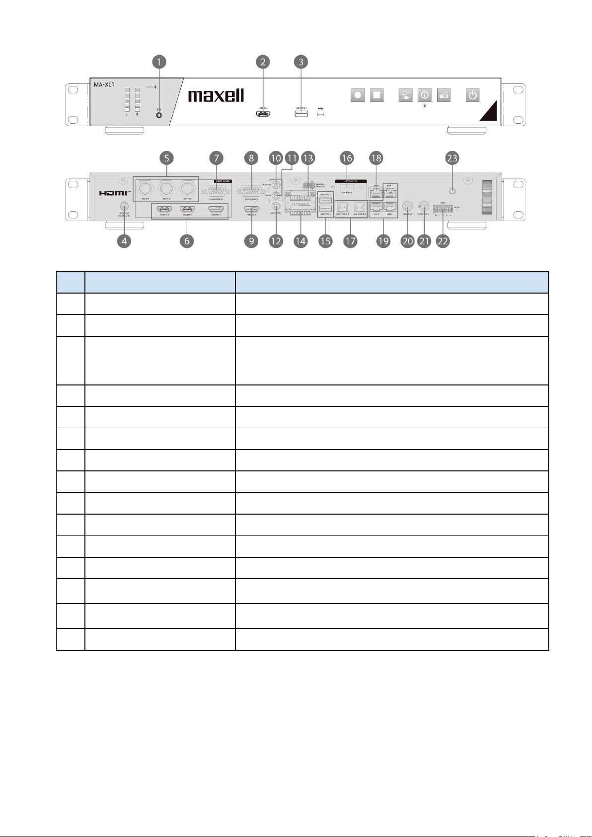
Part names
Lecture Capture Station
(1) Control buttons (6)
(2) Ports (6)
(3) Indicators (110)
(4) Power connector (17)
(5) Rack mount brackets (7)
(6) Security bar (19)
(7) Spacers
(8) Exhaust vent
(9) Intake vents
WARNING
• Do not touch around the exhaust vents during use or just after use, since it is too hot.
CAUTION
• Maintain normal ventilation to prevent the product from heating up. Do not cover, block or plug up
the vents. Do not place anything that can stick or be sucked to the vents, around the intake vents.
Page 6

6
Control buttons
(1) Main power button (29)
(2) Projector power button (29)
(3) Information button (29, 44)
(4) Video switch button (29, 31)
(5) Recording stop button (29, 38)
(6) Recording start button (29, 38)
Ports
(1) SDI IN 1 port
(2) SDI IN 2 port
(3) SDI IN 3 port
(4) COMPUTER IN port
(5) HDMI IN 1 port
(6) HDMI IN 2 port
(7) HDMI IN 3 port
(8) HDMI IN 4 port
(9) MONITOR OUT port
(10) HDMI OUT port
(11) AUDIO IN port
(12) MIC IN port
(13) AUDIO OUT port
(14) Front audio output port
(15) AUDIO IN port (Balanced)
(16) AUDIO OUT port (Balanced)
(17) USB TYPE A port (x2)
(18) USB TYPE A port
(19) USB TYPE A port (Interactive)
(20) USB TYPE B 1 port
(21) USB TYPE B 2 port
(22) WAN port
(23) LAN 1 port
(24) LAN 2 port
(25) LAN 3 port
(26) CONTROL 1 port
(27) CONTROL 2 port
(28) Bluetooth® antenna port
(29) DIDO port
(13)
Page 7

7
Setting up
Install the product according to the environment and manner the product will be used in.
Placement
Please set this product to level. This product can be mounted into a rack (for 19-inch rack) with the
provided “rack mount bracket”. When attaching the rack mount bracket to the main unit, be sure to use
the provided screws. Please follow the manual of the rack to mount.
Please take a distance of more than 2 cm between the product and the wall.
Attach rack mount bracket
1. Attach one of the brackets to the 4 screw holes at the side of the product. Using 4 screws in
accessory box to fix the bracket on the side of the product
2. Do the same steps to complete another side.
3. The product is ready for the rack fixation.
(continued on next page)
Page 8

8
Placement (continued)
WARNING
• Place the product in a stable horizontal position at the direction the spacer is on the bottom. If the
product falls or is knocked over, it could cause injury and/or damage to the product. Using a damaged
product could then result in fire and/or electric shock.
• Do not place the product on an unstable, slanted or vibrational surface such as a wobbly or inclined
stand.
• Place the product in a cool place, and ensure that there is sufficient ventilation. The high temperature
of the product could cause fire, burns and/or malfunction of the product.
• Do not stop-up, block or otherwise cover the product's vents.
• Keep a space of 2 cm or more between the sides of the product and other objects such as walls.
• Do not place or attach anything that would block the product vent holes.
• Do not place the product on metallic thing or anything weak in heat.
• Do not place the product on carpet, cushions or bedding.
• Do not place the product in direct sunlight or near hot objects such as heaters. Do not place anything
near the product vents, or on top of the product. It causes high temperature and could result in fire
or smoke.
• Do not place anything that may be sucked into or stick to the vents on the bottom of the product.
• Do not place the product anyplace where it may get wet. Getting the product wet or inserting liquid
into the product could cause fire, electric shock and/or malfunction of the product.
• Do not place the product in a bathroom or the outdoors.
• Do not place anything containing liquid near the product.
• Do not place the product where any oils, such as cooking or machine oil, are used. Oil may harm the
product, resulting in malfunction, or falling from the mounted position. Do not use adhesive such as
threadlocker, lubricant and so on.
• Use only the mounting accessories the manufacturer specified, and leave installing and removing the
product with the mounting accessories to the service personnel.
• Read and keep the user's manual of the mounting accessories used.
• When attaching the rack mount to the main unit, be sure to use the provided screws. Using other
screws may cause failure, fire, or electric shock.
CAUTION
• Avoid placing the product in smoky, humid or dusty place. Placing the product in such places could
cause fire, electric shock and/or malfunction of the product
• Do not place the product near humidifiers, smoking spaces or a kitchen. Also do not use an ultrasonic
humidifier near the product. Otherwise chlorine and minerals contained in tap water are atomized
and could be deposited in the product causing image degradation or other problems.
• Do not place the product in a place where radio interference may be caused.
• Do not place this product in a magnetic field.
Page 9

9
Product connection
Before connecting the product to a device, consult the manual of the device to confirm that the device
is suitable for connecting with this product and prepare the required accessories, such as a cable in
accord with the signal of the device.
Consult your dealer when the required accessory did not come with this product or the accessory is
damaged.
After making sure that this product and the devices are turned off, perform the connection, according to
the following instructions.
WARNING
• Use only the appropriate accessories. Otherwise it could cause a fire or damage the product and
devices.
- Use only the accessories specified or recommended by this product’s manufacturer. It may be
regulated under some standards.
- Neither disassemble nor modify this product and the accessories.
- Do not use the damaged accessory. Be careful not to damage the accessories. Route a cable so
that it is neither stepped on nor pinched.
• Be careful to the volume When using headphone or earphone. If you continue to use it for a long time
at a loud volume that stimulates your ears, your auditory capacity may be greatly impaired.
CAUTION
• Do not turn on or off the product while connected to a device in operation, unless that is directed in
the manual of the device. Otherwise it may cause malfunction in the device or product.
• Be careful not to mistakenly connect a connector to a wrong port. Otherwise it may cause
malfunction in the device or product.
- When connecting a connector to a port, make sure that the shape of the connector fits the port.
- Tighten the screws to connect a connector equipped with screws to a port.
- Use the cables with straight plugs, not L-shaped ones.
• Before connecting this product to a network system, be sure to obtain the consent of the
administrator of the network.
• Do not connect the WAN/LAN port to any network that might have the excessive voltage.
• Be sure to confirm that the product has been installed and connected safely even if it is turned on
automatically.
• If you connect the product to an existing network, consult a network administrator before setting
server addresses.
• You should be aware of the following:
DO NOT USE NEAR THE FOLLOWING!
- Microwave ovens
- Industrial, scientific or medical devices
- Designated low power radio stations
- Premises radio stations
- Wireless LAN router
- Using this product near the above may cause radio interference, which would result in a decrease in
transmission speed or interruption, and even lead to malfunctioning of devices such as pacemakers.
• Depending on the location where this product is used, radio wave interference may occur, which
may result in a decrease in transmission speed or interruption in communication.
• Bringing this product out of the country or region you reside in and using it there could lead to a
violation of the radio laws of that country or region.
• The product is for indoor use only. Outdoor use is prohibited.
• Be careful to the volume When using headphone or earphone. If you raise the volume too much from
the beginning, you may suddenly get loud noise and damage your ears. Please increase the volume
little by little.
(continued on next page)
Page 10

10
Product connection (continued)
・ To enable the port, login to the Web Interface in Administrator mode and set Media I/O. (48)
[NOTE]
• Before connecting the product to a computer, consult the computer's manual and check the
compatibility of the signal level, the synchronization methods and the display resolution output to
the product.
- Some signal may need an adapter to input this product.
- Some computers have multiple screen display modes that may include some signals switch are not
supported by this product.
(Continued on next page)
Page 11

11
Product connection (continued)
[NOTE]
• If you connect this product and a notebook computer, you need output the display to an external
monitor, or output simultaneously to the internal display and an external monitor. Consult the
computer's manual for the setting.
• This product does not support HDCP encryption & decryption. When input content has HDCP
protection, the HDMI Input may receive no image and connected display may show black screen.
Therefore, if you display content with HDCP protection set, please output directly to an HDCP
supported monitor without passing through this product.
- The HDMITM supports the following signals.
Video input signal: 1920X1080p(60/50/30/25/24Hz), 1280X720p(60/50Hz),
1024X768p(60/70/75Hz),
Video output signal: 1920X1080(60Hz)
Audio signal: Format Linear PCM
Sampling frequency 48kHz / 44.1kHz / 32kHz
- This product can be connected with another equipment that has HDMI™ connector, but with some
equipment the product may not work properly, something like no video.
- Be sure to use an HDMI™ cable that has the HDMI™ logo.
- Use a Category 2-certified HDMI™ cable to input 1920X1080p(50/60Hz) signal to the product.
- When the product is connected with a device having DVI connector, use a DVI to HDMI™ cable to
connect with the HDMI input.
(continued on next page)
Page 12
12
Product connection (continued)
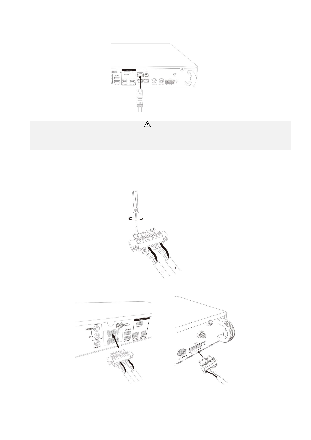
To use network functions of the product, connect the WAN port with the external network. For
connection, use a network cable with RJ45 connector.
CAUTION
• Before connecting the product to a network system, be sure to obtain the consent of the
administrator of the network.
• Do not connect the WAN/LAN port to any network that might have the excessive voltage.
Connect detachable terminal block
When using balanced audio or DIDO, use the supplied detachable block connector.
Loosen the screw of block connector and insert the cable into the port. Then tighten the block connector screw to
fix the cable.
Connect the block connector to the Audio IN terminal or DIDO terminal.
(continued on next page)
Page 13
13
Product connection (continued)
No.
Name
Brief information
1
Front audio output
Output of recording sound for monitoring
2
HDMI IN
HDMI input source
3
USB TYPE A
・ External USB storage device (mp4 video file recording and
snapshot image)
・ Lecture information import with recording
・ Mouse control
4
Power Connector
DC : 24V / 2.5A
5
SDI IN x 3
HD-SDI input
6
Rear HDMI IN x 3
HDMI input source
7
COMPUTER IN
VGA input source for PC
8
MONITOR OUT
VGA output for display
9
HDMI OUT
HDMI output for display
10
AUDIO IN
Line audio input
11
MIC IN
Mic audio input
12
AUDIO IN
Line audio output
13
AUDIO IN(L,R)
Differential line audio input
Refer to below chart for the pin define
14
AUDIO OUT(L,R)
Differential line audio output
Refer to below chart for the pin define
15
USB TYPE A port x 2
For Extended USB storage & Mouse control
(continued on next page)
Page 14

14
No.
Name
Brief information
16
USB TYPE A (INTERACTIVE)
Operation input port by interactive projector and touch monitor
17
USB TYPE B x 2
For PC USB mouse control
18
WAN
RJ-45 Ethernet connector for network connection
19
LAN x 3
RJ-45 Ethernet connectors for network camera input source, &
accessing to web management setting pages, and projector
ON/OFF.
20
CONTROL 1
Mini DIN connector for camera
Refer to below chart for the pin define
21
CONTROL 2
Mini DIN connector for other devices*
*: Hitachi / Maxell Projector & Computer etc.
22
DIDO
Refer to below chart for the pin define
23
Bluetooth antenna port
Antenna for Bluetooth speaker/microphone
(continued on next page)
Page 15

15
Product connection (continued)
RS-232
DIDO
Terminal block
Pin No.
I/O
Description
1 - GND
2 O H while recording
L while recording stop
3 - Reserved
4 - Reserved
5 - Reserved
(continued on next page)
Page 16

16
Product connection (continued)
CONTROL port connection
[NOTE]
• Depending on the device to be connected, the pin assignment may be different. Before connecting,
please refer to the manual of the device to be connected and check the pin assignment.
CONTROL1 port
of the product
RS-232 port
of the camera
CONTROL2 port
of the product
CONTROL2 port
of the product
CONTROL port
of the projector
Page 17

17
Connecting the power supply
1. Connect the power cord to the Power adaptor.
2. Put the DC plug of the power adaptor into the DC 24V connector of the product.
3. Firmly plug the power cord’s plug into the outlet. In a couple of seconds after the power supply
connection, the POWER indicator lights up in steady red.
WARNING
• Please use extra caution when connecting the power adapter and the power cord, as incorrect or
faulty connections may result in fire and/or electrical shock.
• Do not touch the power adapter and the power cord with a wet hand.
• Only use the power adapter and the power cord that came with the product. If it is damaged, consult
your dealer to get a new one. Never modify the power adapter and the power cord.
• Only plug the power cord into an outlet whose voltage is matched to the power cord. The power
outlet should be close to the product and easily accessible. Unplug the power cord for complete
disconnection.
• Do not distribute the power supply to multiple devices. Doing so may overload the outlet and
connectors, loosen the connection, or result in fire, electric shock or other accidents.
• Do not press the main body of product on the power adapter and the power cord.
• Connect the terminal for the AC inlet of power adaptor to the power outlet of the building using an
appropriate power cord (bundled).
• When multiple power cords are included, please use the power cord that matches the outlet shape.
• Do not use with the power adaptor hanging.
• Do not trample the power adaptor or cord.
(continued on next page)
Power Adaptor
Power cord
Page 18

18
Connecting the power supply (continued)
NOTICE
• Do not unplug the power cable during recording. There is a possibility of breaking the recorded data
and breaking the product.
Page 19

19
Using the security bar
A commercially available anti-theft chain or wire can be attached to the security bar on the product.
Refer to the figure to choose an anti-theft chain or wire.
For details, refer the manual of the security tool.
WARNING
• Do not use the security slot to prevent the product from falling down, since it is not designed for it.
CAUTION
• Do not place anti-theft chain or wire near the exhaust vents. It may become too hot.
[NOTE]
• The security bar is not comprehensive theft prevention measures. It is intended to be used as
supplemental theft prevention measure.
Page 20

20
Power on/off
Turning on the power
1. Make sure that the Power adaptor and power cord is firmly and correctly connected to the product
and the outlet.
2. Make sure that the POWER indicator is lighted in steady red.
3. Press the (power) button on the product.
Press the power button to start automatically.
When the power button is pressed, the power indicator lights red and green alternately. When startup
is completed, the indicator lights in steady green.
To display the picture, select an input signal according to the section Video switch (31).
WARNING
• Keep the product out of the reach of children.
[NOTE]
• Turn on any connected devices prior to the product.
• After turning off the power, if the indicator is light in red it is possible to turn on the power.
• This product has the function that can make the product automatically turn on/off. Please refer to section
“System setting” (72), items of the System settings.
Turning off the power
1. Press the POWER button on the product. The message “Shutdown?” appears on the screen for about
10 seconds.
2. Press the POWER button again while the message appears. The POWER indicator will begin blinking
in red. Then the POWER indicator will stop blinking and light in steady red when shutdown completed.
WARNING
• Do not touch around the exhaust vents during use or just after use, since it is too hot.
• Remove the power cord for complete separation. The power outlet should be close to the product
and easily accessible.
Page 21

21
Getting start
Connection of the peripheral devices
Refer to section "Product connection" and connect peripheral devices. (9)
Below check list for reference.
・ Connect interactive projector or touch monitor to both the HDMI output port and Interactive USB port.
If you connect an unsupported interactive projector or touch monitor, the menu bar will not be
displayed. Also, when starting this product for the first time, connect the mouse to the front USB port
to calibrate the touch module. For detail refer to section “Calibration of Touch Module”.(22)
・ Connect audio devices: both input and output
ex: Speaker & Microphone
・ Use RJ45 to connect WAN port with the external network
・ Connect camera via HDMI/SDI/RJ45
・ Connect several cables to reserve for video input sources
ex: HDMI & VGA & SDI
If everything is connected well, you could see the menu ball & toolbar appear in the display.
Page 22

22
Calibration of Touch Module
In some cases, installers would need to do calibration before using touch function.
After connecting interactive projector or touch monitor with the product USB TYPE A port (Interactive),
finding a USB mouse and insert into the front USB port.
Press information button on the front panel to call information dialog.
Moving the mouse cursor to click on calibration icon . Then go through the calibration process with
your figure or the dedicated optical pen of the touch module.
After all the settings finished, start enjoy the easy interface of the product!
Page 23

23
Log into the settings webpage
Prepare a PC for the settings of the first time installation.
Connection via LAN port
Turn on the product and using RJ45 cable to connect PC with the LAN port of the product. Set the PC's
IP address to 192.168.11.XX*. Then open the web browser and input 192.168.11.254 as the URL to
access the product setting page.
Log in web page with default username “admin” and password “lcsadmin”, then entering the system
Administrator webpages.
*
“XX” is any number between 1 and 253
Page 24

24
Connection via WAN port
Turn on the product and using RJ45 cable to connect router with the WAN port of the product. And
connect router to PC with RJ45 cable. Set the PC's IP address to DHCP. Push Information button to get
IP address of the product.
Then open the web browser and input the IP address of the product as the URL to access the product
setting page.
Log in web page with default username “admin” and password “lcsadmin”, then entering the system
Administrator webpages.
Language switching:The product automatically detects PC’s system language and selects the
coordinate language to display. The product also provides Language options on the top-right corner of
the webpage for changing.
[NOTE]
Be sure to change the user name and password of the Administrator / Online Director /
Video Manager after first logging in to the administrator page. Please be careful in
managing user name and password. For details, refer to section "Account". (80)
Page 25

25
Settings of the video and audio input sources
Refer to section “Media I/O” to setup video & audio input sources. (48)
If you use HDMI input, make the following settings.
Go to [Media I/O] [Video inputs] Select the Enable checkbox of the HDMI port number to which the
HDMI output device is connected. For example, if CH1 is selected, select the Enable checkbox of in
the following figure.
If you use network camera, make sure it comply with standard ONVIF before the setting.
Then check if the RJ45 is well connected with the product LAN port and the camera is ON.
Check Camera’s product label and remember the MAC address of the camera.
Come back to Administration webpage.
Go to [Media I/O] [Network Camera Manager] Press [Refresh] button
The network camera should be listed in the table and using MAC address to identify the one in use.
Press “Login” button and input camera’s account name and password* to pass authentication until
“Status” shows “OK”.
Remember the IP address of the camera.
*: To know camera’s account name and password, please refer to the manual of the network camera.
(continued on next page)
Page 26

26
Settings of the video and audio input sources (continued)
Go back to [Media I/O] [Video Inputs] scroll down to [Cam 1 Group].
From “Video Source” drop down list, select “Network Camera”.
Then you will be able to assign the correct camera as the video source via “IP address” and press
“Apply”.
Press icon to enter advanced configuration page and check the video source. For details of advanced
configuration, please refer to section “Content Group / Cam1 Group / Cam2 Group” (51).
Page 27

27
Settings of the conference function
Go to [Conference] and assign the product as the internal conference server or point to an external
server.
As an internal conference server, the product needs to have a fixed/public IP address in order to let
other product access via internet. Check with IT staff to make sure port 1935 & 5070 are not block in the
local network environment.
When set as the external server, means there must be another product already set as the internal
conference server. To join into the same contact list, input the IP address of the product which is set as
the internal server. When the connection built, the conference icon in the toolbar will turn from disable
to be available.
Scroll down to find “Encoder Settings”. Change the video compression profile if necessary.
Then, Go to [System] [System settings] find “Device description”. Give(assign) this product a name
for identification. This name will show in the “call-out list”. And while connection built, users from the
remote site could see this description on the top banner.
(continued on next page)
Page 28

28
Settings of the conference function (continued)
Page 29

29
Button Control
No.
Name
Brief information
1
Recording start
button
Recording start
Pause while recording and click again to resume recording.
2
Recording stop
button
Recording stop
3
Video switch
button
Video source switch; cycling switch for each assigned source
CH1->CH2->CH3, In each CH, follow below order
HDMI1->HDMI2->HDMI3->HDMI4->VGA->SDI1->SD2->SD3->Netw
ork Camera
4
Information
button
Short push:Information list appears and USB mouse control switch back
from PC to the product
Long push:2 sec. Bluetooth pairing start
*The nearest one or the strongest one or the first one would be paired in
pairing mode.
*The product’s Bluetooth module can pair with only one Bluetooth device
at a time. And only one paired device could be kept for auto-connection
next time.
*Bluetooth Auto connection: When any of the Bluetooth devices
disconnected, the product would auto connect to the remembered
Bluetooth device. The retry interval is 5 seconds.
5
Projector power
button
Power on / off button of PJLink compatible projector or Hitachi / Maxell
projector.
6
Main power
button
Power on/off button for the MA-XL1
Short push : pop out a dialog to ask if power off is confirmed.
Long push : power off directly
7
Reset
Users are not allowed to use this reset. For service personnel only.
Page 30

30
Graphical User Interface
When there is any mouse or touch device connected to the product, users could see the graphical user
interface appeared. It includes menu ball and toolbar which carry several of the useful functions for
teachers or presenters.
Menu Ball
The menu ball carries most important information of the system and useful functions. Do a snapshot,
clear all the annotation, control presentation slide page up & down and show recording status. Users
could also move the menu ball to any location of the display for ease of use.
Icons
Function description
Remark
Toolbar switch
• Show device status: Ready
or recording or Pause
• Click to call toolbar
appear/disappear
Long press 2 seconds in any
space to lead the menu ball to
change location
Snapshot
Screen shot of the display
Menu ball & Toolbar will flash
one time to show captured.
Clear all
Clear all the annotation in
current display
-
Timer
Show the recording time
-
Page Up
Control presentation slide
page up
Icons appear only when the
Presentation tool connected with
the product via PC. For details,
refer to section "Presentation
tool ". (101)
If it’s not in full screen mode,
click either on Page Up icon or
Page down icon could enter full
screen mode
Page Down
Control presentation slide
page down
Snapshot function:
Allow users to do snapshot of the display, for both video source and annotation:
The snapshot image would be saved as JPG file into assigned storage*
While users insert front USB storage and activate “front USB recording” function in admin setting page,
JPG file would be saved in both assigned storage* & front USB storage.
While recording, the product would automatically insert an index with thumbnail together with the
snapshot image captured.
The menu ball and toolbar will flash once after snapshot icons pressed to show it works. No graphical
user interface would be taken within the snapshot image.
* Assigned Storage: internal HDD or rear USB storage, please refer to section “Storage”.(64)
: Snapshot from menu ball : Snapshot from playback toolbar
Page 31

31
Toolbar
All the main function icons are in toolbar, and allow users to mirror icons arrangement.
Including video switch, playback, record, conference, annotation and pen ON/OFF, eraser, clear all, pen
color for annotation, pen/eraser width for annotation, audio output adjustment/mute and mirror all
icons.
Video switch
The product allows installers to connect different types of video input sources(HDMI/VGA/SDI/IP
video) and assign them into different channel groups(CH1/CH2/CH3). For details, refer to section
“Video inputs” (49). Besides, during the conferencing mode, it also allows users to select the video
sources from the remote site. Furthermore, the whiteboard groups offer 4 types for selection. Use
video switch icons to choose target video source and show on the display for sharing. In addition, icons
that were not assigned are grayed out.
You can also switch video by using the video switch button on the front panel of the product.
During the conferencing mode, CH3 would be replaced by remote video sources for the ease of
communication and collaboration purpose. Which means users cannot switch to any CH3 video sources
under this mode.
(continued on next page)
Content Group
Camera 1 Group
Camera 2 Group
(or Remote)
Whiteboard Group
CH1
CH2
CH3
Page 32

32
Video switch (continued)
Function descriptions:
Layer 1
Layer 2
Function description
Remark
Video
switch
Channel 1
group for
Content
Select one of the
assigned local content
sources to show on
the display device
HDMI 1 /2 /3 /4 ,
VGA or IP camera ,
encoder for selection
Channel 2
group for
Camera 1
Select one of the local
camera sources to
show on the display
device
HDMI 1 /2 /3 /4 ,
SDI 1 /2 or IP camera
, encoder for selection
Channel 3
group for
Camera 2
Select one of the local
camera sources to
show on the display
device
SDI 3 or IP camera ,
encoder for selection
Remote
Sources
group
Select one layout of
the remote sources to
show on the display
device
Totally 12 layouts for selection
For detail refer to section “Conference”.
(39)
Whiteboard
Group
Select one whiteboard
type to show on the
display device
Whiteboard/
Blackboard/
Whiteboard with grid/
blackboard with gird
Page 33

33
Playback
Allow users to playback snapshot images, existing and current recording files.
• Snapshot preview: show all images captured in hard disk.
• Current recording video: playback current recording video from the start recording time.
• Existing files: all the videos saved in assigned storage could be selected and playback.
After click snapshot preview or existing video icons, a dialog window would pop up to show Image List
or Video List.
Using page up and page down to review Image List or Video List, and select the folder/file you want to
playback.
(continued on next page)
Page 34

34
Playback (continued)
Function descriptions:
Layer 1
Layer 2
Function description
Remark
Playback
Snapshot
images
Show all the folders which
contain snapshot image files
Images taken in the same day are put in
the same folder
Display 4 folders in one page
Image
list
Dialog
Choose any file in
the list to playback
Show Date and numbers of the image files
in the folder
Page up
folder list page up
Page down
folder list page down
Close
Close the dialog
Folder pages list
Click to jump to different folder index page
Current
recording
video
• While recording: playback
current recording video from
start time
• Not recording: playback
latest saved video file
-
Existing
videos
Show all videos saved in hard
disk drive
4 videos in one page
Video list
Dialog
Choose any file in
the list to playback
Show Thumbnail/ Date/ Start-End time/
Video duration
Page up
file list page up
Page down
file list page down
Close
Close the dialog
Video Pages
Click to jump to different video page
After click the folder or video to playback, the display would enter playback mode.
Under playback mode, the function toolbar would be different.
(continued on next page)
Page 35

35
Playback (continued)
Image playback mode:
Function descriptions:
Icons
Function description
Remark
Mirror
Function icons rearrange from left
←→ right
Playback mode toolbar
Exit
Exit the playback mode and back to
the main toolbar
-
Snapshot
Screen capture during playback
mode
-
First Image
Jump to the first Image
Previous image
Show previous image
-
Next image
Show next image
-
Last Image
Jump to the last Image
Folder
information
Show the date when the folder built
-
Image number
Show the current image number
from total images in the folder
-
Annotation
toolbar
Eraser
Eraser the part mouse move over
Clear all
Clear all the annotation on playback
mode
Pen color
Change color to white/ black/ yellow/
blue/ green/ red/ orange/ purple
Pen width
Pen: 3/6/9/12 pixels
Eraser: 16/32/48/64 pixels
(continued on next page)
Page 36

36
Playback (continued)
Video playback mode:
(continued on next page)
Page 37

37
Playback (continued)
Function descriptions:
Icons
Function description
Remark
Mirror
Re-arrange Function icons from left
←→ right
Playback mode toolbar
Exit
Exit the playback mode and back to
the main toolbar
-
Snapshot
Screen capture during playback
mode
-
Index list
Show Index list attached with this
playback video
4 Index items in one page
Index list
dialog
Choose any Index to
jump to the
correspondent time
stamp to playback
Show Thumbnail/ Index title/ Index time
Page up
Index list page up
Page down
Index list page down
Close
Close the dialog
Index Pages
Click to jump to different Index list page
Source switch
Switch between different video
source while playback
Only available if the recording video
include individual source files
Last Index
Skip to last Index time stamp to
playback
-
Play/Pause
Playback chosen video
While the video is playing, click to
pause and click again to resume
-
Next Index
Skip to next Index time stamp to
playback
-
Time bar
Show playback progress in bar
Click any point on the bar will jump to
correspondent time
-
Time
information
Show total recording time & current
playback time
-
Audio On/Off
Mute or resume playback audio
-
Volume bar
Show playback volume level
Click any point on the bar will adjust
to correspondent volume level
-
Annotation
panel
Eraser
Eraser the part mouse move over
Clear all
Clear all the annotation on playback mode
Pen color
Change color to white/ black/ yellow/
blue/ green/ red/ orange/ purple
Pen width
Pen: 3/6/9/12 pixels
Eraser: 16/32/48/64 pixels
Page 38

38
Record
The product supports lecture capture functions. From graphic user interface, users could do simple
recording controls which including recording start/pause/stop, layouts preview and selection.
After recording start, the icon of Record will change to Pause. Icon changes to Record during pause and
click on record icon to resume recording. You can also recording start/pause/stop by using the
recording start/stop button on the front panel of the product.
Function descriptions:
Layer 1
Layer 2
Function
description
Remark
Recording
Snapshot
Screen shot of the
display
Menu ball & Toolbar will flash one time to show
captured.
Record
Start recording
Click to Pause
while recording
Recording icon on toolbar change to yellow while
recording
Pause
Click to resume
recording
-
Stop
Stop recording
-
Layout
selection
Click to select
recording layout
• Single source(Display content)/
• Picture in Picture(Display content big + Camera
1 small)/
• Picture by Picture (Display content + Camera 1)/
• Triple sources: (Display content + Local camera
1 + Remote camera 1 or Display content + Local
camera 1 + Local camera 2)
While the recording time of the internal HDD or external USB storage is limited, a confirm dialog will
show on screen to remind users that the maximum time length of current recoding job, users could
confirm to record or cancel recording attempt.
(continued on next page)
Page 39

39
Record (continued)
After recording start, all menu and confirmed dialog will disappear, only menu ball appear and the
timer start.
[NOTE]
• Maximum time length of a recording video file is 8 hours.
• A dialog will be displayed to show the available recording time if the recordable time is 8 hours or
less. The system will only show the less one between internal HDD and the front USB storage.
• If front USB storage is FAT32 format, the maximum file size is 4GB.
• If front USB storage is NTFS format, maximum recording time would be based on USB storage free
space & recording profile
• Recording will be stopped under below conditions:
- Remaining time is zero
- HDD or front USB storage cannot be access
- HDD or front USB storage cannot be read/write
Conference
The product provides an easy way of conferencing and collaboration functions.
(continued on next page)
Hang-up
Visiable when conferencing
Collaboration
ON/OFF
Icon become yellow when conferencing
Page 40

40
Conference (continued)
Function descriptions:
Layer 1
Layer 2
Function description
Remark
Conference
Open Contact
list
Show Contact list
-
Contact
list
Show local
device name
-
Show
destination
devices names
Green: ready for call
Black: device not available
Red: Busy
Yellow: waiting for connection
Click to choose
one destination
device and make
a call
Accept or Refuse icons s in call in
dialog
Stop icon in call out dialog
Conferencing icon on toolbar change
to yellow while connected
Close the dialog
-
Hang-up
Disconnect the
conferencing
-
Collaboration
on/off
Collaboration
enable/disable
[NOTE]
• When the call is waiting for acceptance, the product would keep playing a ring tone.
• If anyone is in a conference call in the list, you cannot call out.
• If the call doesn’t be accepted within 15 seconds, the dialog will disappear and the ring tone will
stop.
After the call been accepted, the ring tone would be stopped, and a bar shows the remote name at the
top area of the display, an icon shows when collaboration is ON.
Furthermore, the display will show Camera 1 Picture-in-Picture. The big window shows remote camera
1 while the small window shows local camera 1.
Use video switch to select target video input source for display and collaboration. For details, refer to
section “Video switch” (31)
Hang up the call by clicking the icon at the right side of the bar or click the icon in main toolbar.
(continued on next page)
Page 41

41
Conference (continued)
Collaboration
When users enable collaboration function, annotations from each site would be shown on both screens,
and any change of the video source on display would automatically apply to another site to make sure
the users from two sites could see the same content on display.
Collaboration ON Collaboration OFF
Refer to the table below for the displayed content.
Device-A (Local site)
[A ]: content channel (CH1 of Device-A)
[a] : camera channel (CH2 of Device-A)
Device-B (Remote site)
[B] : content channel (CH1 of Device-B)
[b] : camera channel (CH2 of Device-B)
Device-A
Device-B
Video
Source
Description
Local
Display
Auto
Switch
Description
Local
Display
Local content
(Local CH1)
[A]
Remote content
(Remote CH1)
[A]
Local camera
(Local Ch2)
[a]
Remote camera
(Remote CH2)
[a]
Local whiteboard
[WB]
Local whiteboard
[WB]
Local playback
[Play]
Remote content
(Remote playback)
[Play]
Remote content
(Remote CH1)
[B]
Local content
(Local CH1)
[B]
Remote camera
(Remote CH2)
[b]
Local camera
(Local CH2)
[b]
Local content + Remote content
(Local CH1+ Remote CH1)
[A+B]
Remote content + Local
content
(Remote CH1+ Local CH1)
[A+B]
Local content + Remote camera
(Local CH1+ Remote CH2)
[A+b]
Remote content + Local camera
(Remote CH1+ Local CH2)
[A+b]
Local camera + Remote content
(Local CH2+ Remote CH1)
[a+B]
Remote camera + Local content
(Remote CH2+ Local CH1)
[a+B]
Local camera + Remote camera
(Local CH2+ Remote CH2)
[a+b]
Remote camera + Local camera
(Remote CH2+ Local CH2)
[a+b]
Remote camera + Local camera
(Remote CH2+ Local CH2)
[b+a]
Remote camera + Local camera
(Remote CH2+ Local CH2)
[a+b]
Local content + Remote camera
(Local CH1+ Remote CH2)
[A+b]
Remote content + Remote
camera
(Remote CH1+ Remote CH2)
[A+a]
Remote content + Remote camera
(Remote CH1+ Remote CH2)
[B+b]
Local content + Remote camera
(Local CH1+ Remote CH2)
[B+a]
After hang-up the phone, the display source will return to CH1 & system will remember the source
before the connection built.
(continued on next page)
Page 42

42
Conference (continued)
Display layout for Conference
The display will show Picture-in-Picture. Big window for remote camera 1 and small window for local
camera 1 video.
Meanwhile, the video switch function on toolbar will switch from Camera 2 to remote sources. Allow
users to switch remote Content/Camera 1/Picture-in-picture/Content side-by-side/Camera 1
side-by-side/Camera 1 picture-in-picture.
Icon
Description
Display Layout
Local content video
(Local CH1)
Full screen
Local camera 1 video
(Local CH2)
Full screen
Local whiteboard
Full screen
Remote content video
(Remote CH1)
Full screen
Remote camera 1 video
(Remote CH2)
Full screen
Local content + remote content
(Local CH1 + Remote CH1)
Picture-by-picture
Left : Local content
Right : Remote content
Local content + remote camera 1
(Local CH1 + Remote CH2)
Picture-by-picture
Left : Local content
Right : Remote camera 1
Local camera 1 + remote content
(Local CH2 + Remote CH1)
Picture-by-picture
Left : Local camera 1
Right : Remote content
Local camera 1 + remote camera
(Local CH2 + Remote CH2)
Picture-by-picture
Left : Local camera 1
Right : Remote camera 1
Local camera 1 + remote camera 1
(Local CH2 + Remote CH2)
*Default layout when conference connected
Picture-in-picture
Full screen : Remote camera 1
Top-right : Local camera 1
Local content + remote camera 1
(Local CH1 + Remote CH2)
*Default layout when conference connected
Picture-in-picture
Full screen : Local content
Top-right : Remote camera 1
Remote content + camera 1 video
(Remote CH1 + CH2)
Picture-in-picture
Full screen : Remote content
Top-right : Remote camera 1
Content Group
Camera 1 Group
Camera 2 Group
(or Remote)
Whiteboard Group
Remote
Page 43

43
Annotation
Using the interactive projectors or touch monitors, the product could allow users to do annotation on
still images, videos and a white board. It supports 8 colors and 4 sizes of the width could be selected.
Function descriptions:
Layer 1
Layer 2
Function description
Remark
Annotation
and Pen
ON/OFF
-
OFF: Hide all the annotations and
show mouse cursor only
ON: show all existing annotations
Eraser
-
Eraser the part mouse move over
-
Clear all
-
Clear annotation on display
Long click 2 sec. Could pop-out
dialog to confirm if clear all
annotation for each input source
-
Pen color
8 colors
Change color to white/ black/
yellow/ blue/ green/ red/ orange/
purple
-
Pen width
4 sizes
Pen: 3/6/9/12 pixels
Eraser: 16/32/48/64 pixels
Default Pen size: 3 pixels
Default Eraser size: 64 pixels
[NOTE]
• The product only supports single touch annotation. Multiple-touch behavior may cause
un-expected result.
• During the conference mode, the annotation on different video sources would be at the
same layer.
Page 44

44
Master Audio adjustment
A master volume control bar allows users to mute or adjust the audio volume for the speakers.
Function descriptions:
Layer 1
Layer 2
Function description
Remark
Volume
Adjustment
Volume
level
Click to show volume bar
-
Volume bar
Show volume level
Click any point on the bar
will jump to
correspondent level
Mute
Mute & Resume
Mute on:
icon become yellow
Mute off:
icon become white
Information Button
Push the Information button on the product front panel could show device information and allow device
manager to do VGA H position adjustment, HID calibration, USB control switch and power off.
Info List
Item
Description
Host Name
For network management use
Device Description
ID to show on conference contact list.
IP Address
For accessing to the web control interface
Model
Show the model name of this product
Version
For maintenance or service identification
Brand
Show the manufacturer information about this product
(continued on next page)
Mute
Volume Adjust
Volume Bar
Page 45

45
Information Button (continued)
Function descriptions:
Button
Information / icons
Function description
Information
Show device information
Host Name/ Device Description/ IP Address/ Mode/
Firmware version/ Manufacturer
Power OFF icon
Power OFF the product & Projector
External USB Host icon
Click to switch USB HID to external host(ex. PC), HID
goes to Host 1(USB Type-B 1) when current video
source is CH1, and HID goes to Host 2(USB Type-B 2)
when current video source is CH2.
Menu ball & Toolbar will disappear after click this icon.
HID Calibration icon
See below illustration
VGA H Adjust icon
Adjust the VGA input H offset position
Adjust the VGA input H offset phase
Close icon
Close information dialog
HID calibration: some of the interactive projector / touch monitor need to be calibrated before use.
Use USB mouse device to click the calibration icon to start.
First appears the Touch Module list, select one and then start the calibration process.
Use touch pen or finger to click on the center of the red circles/dots one by one. Totally 5 circles/dots,
and each circle/dot keep 30 seconds for time out.
[NOTE]
• Both HID Calibration & External USB Host icons appears while HID such as interactive
projector or touch monitor connected.
Page 46

46
Lecture information import
Users could edit a text file for the lecture(video) information and this information would be recorded
together with the video and be uploaded to the video server.
1. Edit the video information based on below instruction and save into the USB storage.
2. The file name should be defined as “lcs_user_config.ini”
3. The data should be written in below format.
Add an arbitrary character string after "=".
[Content Information]
Title =
Organization =
Department =
Event_date =
Semester =
Topic =
Level =
Audience =
Room =
Category =
Presenter =
Section =
Description =
4. Insert the USB storage into the product front USB port. The product will recognize the data with
pre-defined format and import the data to combine with recording file and show in video manager
UI.
5. After the product read and confirm the data, a dialog will show on GUI.
6. Press Confirm button to continue.
[NOTE]
• Available characters: 1024 Unicode for Description and 256 Unicode for the others.
• If “;” is inserted before the item name, that item will be ignored.
Page 47

47
Web Interface
Overview of the Web Interface
The product web interface has three user modes, which are described in detail in the following
chapters:
User mode
Description
Administrator
To setup the device, logging into Administrator with default username
“admin” and password “lcsadmin”. The admin account provides highest
priority to log into all three user modes.
Online Director
For quick start recording and video source switching, logging into Online
director mode from the initial login page with default username “director”
and password “lcsdirector”. This user also could access to Video Manager
web pages and recording related pages in administration.
Video Manager
If you only need to access to the recordings, log in Video Manager with
default username “video” and password “lcsvideo”.
Log-in Authorization
Administrator
Online
Director
Video
Manager
Administrator
V
(Default page)
V
V
Online Director
V
(Video setting page
only)
V
(Default page)
V
Video Manager
V
(Default page)
[NOTE]
Be sure to change the user name and password of the Administrator / Online Director /
Video Manager after first logging in to the administrator page. Please be careful in
managing user name and password. For details, refer to section "Account". (80)
Page 48

48
Administrator
The Administrator web pages provide a system administration interface of the product:It includes
Media I/O, Video, Storage, Scheduler, Upload, Conference, System, Account settings.
NOTICE
Pay attention to the configuration setting. There is a possibility of data deletion and information leak if
you make wrong setting.
[NOTE]
• Pay attention to the configuration setting. There is a possibility of data deletion and information
leak if you make wrong setting.
• After changing the setting, be sure to back up the configuration file by exporting the configuration
file. For details on backing up the configuration file, refer to section “Configuration”. (76)
Media I/O
Media I/O settings help you assign video inputs to each video channel, camera authentication, PTZ
control setting and audio related adjustment. The functions within “Media I/O” include the following:
Item
Description
Video inputs
Select video source to do settings, enable/disable video capture sources,
change sources icon and assign PTZ control method for each input.
Network device
manager
Search & list all the connected network cameras. Camera management
including authentication & delete.
PTZ control port
Set the product RS-232 serial port for the control of PTZ cameras or other
PTZ devices.
Audio
Adjust the volume and set the audio input gain.
Page 49

49
Video inputs
The product is capable to process up to three video inputs at the same time. The name of each input
could be defined by administrators; the default value is “Content”, “Cam 1” and “Cam 2”. The icon on
display could also be changed (default icons show CH1/CH2/CH3). Click on the icon, one dialog carries
all the options would pop up for selection.
(continued on next page)
Page 50

50
Video inputs (continued)
[NOTE]
• Ch2 is dedicated to camera, please assign a camera to Ch2. Assigning other video or content
may cause the video to be distorted or change color.
• The video recorded with this product may not be used without permission by the right owner
under the copyright law.
• When using a device such as a camera, please take responsibility for the subject's privacy,
portrait right, copyright on your responsibility. Appropriately respond to privacy, portrait right,
copyright, etc. by getting consent beforehand from the person who becomes the subject at
your own risk as necessary. The manufacturer does not assume any responsibility for
infringement acts on portrait rights, copyright, etc. using this product, or illegal acts, etc.
Page 51

51
Content Group / Cam 1 Group / Cam 2 Group
Video source can be chosen as Video port, Network Camera, or Encoder.
Item
Description
Video port
Check the box to select Video source: The product provides HDMI, VGA and SDI input
options.
・ Content Group : can select HDMI 1/ HDMI 2/ HDMI 3/HDMI 4/ VGA
・ Cam-1 Group : can select HDMI 1/ HDMI 2/ HDMI 3/HDMI 4/ SDI 1/ SDI 2
・ Cam-2 Group : can select SDI 3 only
While connect with PC via USB type B, it is necessary to assign USB host to be USB 1
or USB 2
Note: For HDMI1~4 port, when anyone be assigned in CH2, it would not show in CH2
for selection.
(continued on next page)
Page 52

52
Item
Description
Network
Camera
Select IP address: Select from the drop-down list of the available cameras which
shows authentication OK and also be well connected.
Note: A login authentication with the camera might be required. Refer to section
“Network camera manager” for more details. (54)
Encoder
Select Protocol: The available options are RTP, RTSP, or RTMP. Enter the primary and
secondary URL which provided by the encoder or stream server. Primary stream would
be used for recording; where secondary URL would be used for director preview.
PTZ control:The product web interface could control PTZ cameras and provides two control methods,
Over IP or via Serial port.
Serial port : When PTZ cameras connect with the product via RS-232 port. For detail refer to section
“PTZ control port”. (55)
Over IP : The option is available when the network cameras comply with ONVIF profile S.
Page 53

53
Advanced configuration
Provide video preview and further configuration of the assigned video input device. After the video
input setting is successfully applied, click to enter the advanced configuration page. In the case of
a PTZ camera, the 9key directional control panel, zoom in/out bar, and up to 8 preset points are
available for control.
No.
Description
①
The preview of the assigned video input.
②
Direction control panel: Click the arrow icons to control camera pan and tilt.
③
Movement speed: Move leftward or rightward to set camera’s moving speed.
④
Zoom in/out: Click the zoom in & out icons or drag the control bar.
⑤
Preset positions: Click the icons to drive camera to the preset position.
⑥
Change preset positions: Click the icon to change the preset positions. Select any of the
P01~P08, move the camera to the new position by using the direction control panel and the
zoom in/out control. Click Save icon to complete the change or click Cancel icon to give it up.
⑦
Brightness, sharpness, and contrast: Slide the bar left or right to change the camera image
settings.
⑧
Visit the camera website icon: Click the icon to enter the camera management webpage. Check
camera’s manual for the account name and password, and input them into the pop-up
authentication dialog.
⑨
Click icon at upper left corner to return to the last page.
Page 54

54
Network camera manager
The Network camera manager page can display/scan the network camera connected to the product.
Network cameras connected before product startup are automatically scanned.
You may click Refresh icon to scan again. Click Login icon and the login authentication dialog would pop
out.
Enter the username and password of the camera to complete the authentication.
The status then changes to OK, which indicates it is available for video input selection.
[NOTE]
• If you fail to find your camera by clicking on “Refresh”, it means the camera may not comply with
standard ONVI
F. If the camera supports RTSP streaming, you could try in another way to get the
video stream. Select “Signal type” as “Encoder” in the “Video Inputs” and check the camera’s
manual to find out camera’s RTSP streaming URL. Then fill in the URL into the encoder setting
page.
• If ONVIF authentication of the camera is set to OFF, please press the authentication icon with
Username and Password blank.
Page 55

55
PTZ control port
The product facilitates the users control PTZ cameras via web interface. Before making any changes on
the configuration, please get to know about the RS-232 settings of the assigned PTZ camera. The
following information must be identified first
Protocol : Available options are VISCA, PELCO-D, and PELCO-P;
Baud rate : 2400, 4800, 9600, and 115200
Audio
Adjust the volume and select the input source. Press Default icon, the volume will be back to factory
default.
Input volume control: Adjust the volume of each audio input. The configurable range is 0-125. The
volume meter indicates the energy of the current volume. In addition, you can set it to mute by clicking
the icon.
Click for advanced settings.
In advanced settings, for Line-in, Line-in(Balanced), and Mic-in/Bluetooth, there are 3 levels of gain
could be selected.
(continued on next page)
Page 56

56
Audio (continued)
Recording volume control: Adjust the volume for recording & streaming. The configurable range is
0-125. The volume meter indicates the energy of the current volume.
Output volume control: Adjust the audio output (via HDMI/Line-out/Bluetooth) volume. Switch
Audio output loop through ON/ OFF.
[NOTE]
When speaker is connected via Bluetooth, it will be output in monaural sound.
Page 57

57
Video
The Video setting pages provides recording & streaming related configurations. The functions within
“Video” include the following:
Item
Description
Recording
Configure recording mode, profile and Index related settings
Streaming
Configure streaming mode, profile and URL.
Content
Edit the video information which could be uploaded/downloaded
together with the mp4 file.
Theme
Add the overlay and background images.
Recording
Encoder settings
Item
Description
Recording mode
Available options are MP4 Mixed video only, MP4 Mixed video with original
sources and OFF.
Video compression
There are 7 compression profiles for selection (Refer to the table below).
Select one to see the detail information at the right side. You may also choose
“User defined” for advanced settings.
Front USB recording
Switch between ON/OFF to enable/disable the product front USB recording
function. Make sure the connected USB storage can be normally read and
written and have enough space for the recording time.
Loop recording
Switch between ON/OFF to enable/disable loop recording function.
Click Apply icon at the bottom when configuration finished.
(continued on next page)
Page 58

58
Recording (continued)
[NOTE]
• No matter ON/OFF of Front USB recording, users still could save snapshot image when they
insert USB storage into the front port.
• When you record on USB flash drive or USB HDD, it may be playable on other devices.
7 video compression profiles:
Profile name
Video Resolution/
Bitrate
Application description
Full HD
1080p/ 4Mbps
Dynamic scene and large local hard disk recording.
Internet Full HD
1080p/ 3Mbps
General scene and medium local hard disk recording.
HD
720p/ 2Mbps
Static scene and small local hard disk recording.
Internet HD
720p/ 1.5Mbps
Live broadcasting through the Internet.
SD
480p/ 800kbps
Static scene for live broadcasting through the
Internet.
Mobile SD
480p/ 500kbps
Live broadcasting for portable mobile devices
watching.
User defined
Click icon for more
options to configure, and
click Save icon after
making any change.
Page 59

59
Index settings:
Item
Description
Add
automatically
Select on if you want to add indexes automatically during recording.
Refer to the table below for conditions.
Additional condition of index
Add automatically
Functions
Trigger
Only on
Presentation tool
Slides changed
Video Switch
Each video switch
Playback mode
Enter/Esc playback mode
Conference mode
Connection start/Hang up
On and off
Menu ball
Snapshot icon
Playback mode
Snapshot icon
Web Director
Snapshot icon
Web Director- Presenter
Input text & press Snapshot icon
Mobile controller
Input text & press Snapshot icon
Video Manager
Add/delete Index
Add prefix to video filename:
Item
Description
Prefix setting
This description would be added to the video filename as a prefix string for
Download and Upload.
Page 60

60
Streaming
Streaming profile could be independent from recording one. Normally for the smooth of the video
stream transferred through network, especially for internet, users may need a smaller bitrate and
resolution. Here allow you to change the profile to fit in local network environment.
Encoder settings:
Item
Description
Video
compression
There are 7 streaming compression profiles for different resolutions and bitrates.
Select a proper one to see the detail information at the right side.
Remember to click “Apply” icon after settings finished.
Click
icon
for more options and click “Save”
icon
after making any change.
[NOTE]
• The product does not protect streaming contents. Take security measures by yourself.
• It’s not allowed to choose the resolutions of the streaming larger than recording one.
For example, if you already choose HD resolution for recording, then the maximum resolution for
streaming profile is HD. No Full HD could be selected.
• About the 7 streaming profiles please refer to section “Recording”. (57)
(continued on next page)
Page 61

61
Streaming (continued)
Streaming settings:
Item
Description
Live
streaming
4 available options for streaming control
OFF : No streaming
Together with recording : Streaming control together with recording icons
Streaming always : Always streaming after power-on.
Independent streaming control : Recording and Streaming are controlled by
independent icons. Streaming start / stop by LIVE icons. It does not work with
recording.
URL
Input target streaming server URL into the blank column. For the RTMP stream, some
servers provide the server URL and key separately. Please connect server URL and
the key together with “/”.
Click on for RTMP name/password if necessary.
Protocol
The available protocols on the product are RTP and RTMP, the URL format is as
follows:
RTMP: In the protocol setting field, copy and paste the Server or Stream URL and
Stream name provided by your CDN (Content Delivery Network) or server
administrator in the format of rtmp://serverurl/streamkey.
RTP: Enter the destination IP address and the port number in the format of
rtp://@ip_address:port_number.
For example, rtp://@226.10.24.32:7000
[NOTE]
• The LIVE icon exists in Online director and mobile controller. (81, 103)
• Please refer to the server manual for the URL.
Page 62

62
Content
The product offers up to 15 user-configurable items for describing content.
It includes Title, Organization, Department, Event_Date, Semester, Topic, Level, Audience, Room,
Category, Presenter, Section, Descriptions.
Only 256 Unicode characters for “Description”; the others are 24 Unicode characters
These texts messages will be saved and attached with the recording files.
[NOTE]
This setting would not be applied to the existing recording files, only for the coming recording
event. To edit or check the existing files information, refer to section “Video Manager”.(94)
Page 63

63
Theme
The product provides three overlays and three backgrounds for selection. Users could design and
upload their own image files for more options.
Administrator user mode adds and deletes images. Layout to the recording screen is done in Online
Director user mode. For details, refer to section “Overlay/Background Selection”. (90)
Item
Description
Overlay
Allow users to select and delete the overlay files. Or click [ ]icon and
select the file in the open dialog to upload for more options.
Background
Allow administrators to select and delete the background files.. Click
[ ]icon and select the desired file in the Open dialog box.
[NOTE]
• The overlay file must be in PNG format, maximum size 1920px x 1080px.
• The background file must be in PNG format, maximum size 1920px x 1080px.
Page 64

64
Storage
Allow administrators to select local storage sources, show embedded disk information and format.
Record disk settings
Item
Description
Local storage
Available options are internal hard disk drive(default) and external USB
storage. Select external USB storage to save recording files to a USB hard
disk connected with the product rear USB port.
Disk information
Show disk information, available storage space and total capacity.
Click Format: The product allows administrator to connect external USB
storage via rear USB port to replace internal HDD. However, to work the
same as internal HDD, this USB storage must be format for the product
access, read/write as a better efficiency and performance.
NOTICE
• This product supports only Partition style MBR. As GPT is not supported, it is not possible to connect
GPT format HDD or USB storage.
[NOTE]
• Because format function will overwrite all the existing data saved in HDD, make sure all the data
is backup well or deleted before clicking the icon.
• Please upload the data recorded with this product to the server within 24 hours. HDD is for
temporary storage. Manufacturers do not guarantee data. Therefore, when recording important
scenes, record with two products and record backup data. For details on uploading data, refer to
section “Upload”. (67)
• The product supports USB storage formatted with FAT32, NTFS, EXT2, EXT3, or EXT4. And the
product supports USB storage of 2TB or less.
Scheduler
Support 3 kinds of schedule/calendar import for scheduled recording.
Available options are Scheduling via Opencast server, Manual Calendar import, and Periodic Calendar
import.
(continued on next page)
Page 65

65
Scheduler (continued)
Schedule settings
Item
Description
Scheduling via
Opencast server
Leverage scheduling interface on Opencast server, the product will synchronize
with Opencast server periodically.
Enter the Capture agent name、Username、Password and iCalendar URL in these
fields.
Capture agent name: the ID to recognize the product on Opencast platform
Username: Opencast user account
Password: Opencast user password
URL: Opencast server URL
1. Click Apply. The product will try to connect with Opencast server then show
successful message. If it show failed, please check the network condition or
contact the manager of the opencast server.
2. Go to Opencast server’s administration interface and double check if the
product is correctly registered on Opencast.
Manual Calendar
import
Importing iCalendar files manually
1. Click Import. An Open window pops up.
2. Select an iCalendar file from the PC to import. The file must have a *.ics file
extension. Click open icon to confirm.
3. Click Apply to import. The event schedule would be added and appears in the
calendar on the Scheduled Events page.
(continued on next page)
Page 66

66
Item
Description
Periodic Calendar import
Importing iCalendar files automatically
Fill in the iCalendar URL.
Click Apply. The assigned schedule would be added and shows in the
calendar on the Scheduled Events page.
[NOTE]
The product scheduler cannot include cycling events, only accept one-time event. Furthermore,
Scheduler also cannot allow more than 2 events to start at the same time. When two events’ time
periods are partially overlapped, the product would only pick the earlier one and drop the other.
Click :Open Scheduled Events page.
Content information:
When users set content information in platform’s interface, it will be synchronized to the product’s
content info and attach with the video after the recording.
(continued on next page)
Page 67

67
Scheduler (continued)
Opencast
iCAL
The product content info.
Title
SUMMARY
Title
Description
DESCRIPTION
Description
Location
= Capture Device
= Device Description
LOCATION
Room
Presenter (1st)
1. ATTENDEE (mail to)
2. ORGANIZER (mail to)
Presenter
Start
DTSTART
Start_Time
End
DTEND
End_Time
Recording interruption
While recording by schedule, you cannot stop recording from the front panel button and the toolbar.
To stop recording by schedule, click Stop.
Upload
The product allows administrators to set a target server as the destination for recording files uploading.
Connection test is the icon for testing after the setting completed.
Item
Description
Auto upload
Select from “OFF” or enable uploading "After recording is completed”.
Followings to be configured according to the upload destination.
Mode
Select network server type: FTP/SFTP/Kaltura/Panopto/OpenCast
HTTP/OpenCast HTTPS
For the operation method of Kaltura / Panopto / OpenCast, refer to the
manual of each service.
IP address, port, or
domain name
Fill in server information
Folder
Assign the folder name as the uploading destination.
Authentication
Select authentication type. Normal or Anonymous
Connection test
Click the Connection test icon and the product will try to connect the server
and show the result.
Click Apply after the settings are completed.
The upload status/result will be shown in the Video Manager web pages. (94)
Page 68

68
Conference
The product supports one-on-one conferencing function. Users in two different locations could
communicate with each other by two product devices via internet or intranet.
For the settings, it follows server-clients structure.
Max. 100 products can join one internal service unit (including itself), 99 other products will show on
contact list, and only one conference connection allowed at the same time.
As a service server, this product needs to be assigned as “Internal” from the drop down list.
When act as a client, the other product need to be set as “external”.
(continued on next page)
Page 69

69
Conference (continued)
Conference settings:
Item
Description
Conference service
Internal: Set the product as conference server, the port number is 5070.
Contact list : List all the other products connected to this product. Click
"Clear All" to clear all the registered products. The contact list would be
blank until administrators registered new units.
external : Set the product as client.
IP address : Fill in the conference server’s IP address.
Port : Fill in the same number as the Internal conference server’s port
number
(continued on next page)
Page 70

70
Conference (continued)
Encoder settings
Item
Description
Video compression
The compression profiles of the conferencing could be different from
recording and streaming. Conferencing stream has another 7 profiles for
selection. Select one to see the detail information at the right side. You may
also choose “User defined” for advanced settings.
7 video compression profiles of conferencing:
Profile name
Video Resolution/
Bitrate
Application description
Internet Full HD
1080p/ 3Mbps
Dynamic scene and good bandwidth for high
resolution & quality of audio/video.
Conference Full HD
1080p/ 1.5Mbps
General scene and enough bandwidth for high
resolution video.
Internet HD
720p/ 1.5Mbps
Static scene and enough bandwidth for HD resolution
video.
Conference HD
720p/ 1.2Mbps
Fit to normal network environment with HD
resolution video.
SD
480p/ 800kbps
Limited bandwidth with acceptable resolution &
audio/video quality.
Mobile SD
480p/ 500kbps
Limited bandwidth with acceptable resolution.
User defined
Click icon for
more options to
configure, and click
Save icon after
making any change.
(continued on next page)
Page 71

71
Conference (continued)
Service information
Item
Description
Device description
Displays the Device description of the product.
This is the device name displayed in the contact list.
Device description can be changed. For details, refer to “System
settings”. (72)
Conference version
Conference version is displayed.
Page 72

72
System
System function page includes basic settings and the information of this device. The functions within
“System” include the following:
Item
Description
System setting
Contains device identification, date and time configuration, and
booting settings
Network
IP assignment for network connection
Configuration
Export /Import the configuration & Reset
Service
Displays the current firmware version, and provides web-based way
to update firmware, download system log, and restart.
Display
Settings related to local display/projector
System settings
Device identification
Allow administrator to change the host name and description. Remember to click “Apply” in the bottom
area.
Item
Description
Host Name
As a network device, the product would be identified by other network
devices by host name.
Device description
For conferencing function, this product will be identified as this
description.
Show other system
information
Brand, Model, Serial number & MAC address.
(continued on next page)
Page 73

73
System settings (continued)
Date and Time:
Show current time, set time zone and select time setting mode.
Item
Description
Device current date and
time
Show current time in format of YYYY-MM-DD hh-mm-ss
Time zone
Drop list for manual or auto select the time zone.
Setting mode
NTP service: Users could use default URL or input own NTP server URL.
Manually set: Users could press the icon to synchronize with PC or
manually input date and time.
Set Date & Time: Click on to call calendar for setting. Or click on the
time blank to get the cursor and use keyboard to key in directly.
• : Switch to time setting page
• : Close the window. If users click on other area outside this window,
also the window will be closed.
• : Switch to previous/next month or year
• Chose any date to assign the date information
• Click on “Month Year”, will switch to Month setting page.
(continued on next page)
Page 74

74
Item
Description
Setting mode
(Continued)
• : Switch to date setting page
• : Increase/decrease the number of the time. Or click on the
number will show numbers for selection. For the hours is from 00~23. For
the minutes and seconds, the options use “5” as the interval. Totally 12
numbers to choose.
Boot image:
Item
Description
Boot image
Change the boot screen image file. The boot screen is the image you will
see when booting up the device.
Click Browse icon and select the image file from your PC to upload. Then
click “Apply”
[NOTE]
The boot screen file must be in PNG format, maximum size 1920x1080px.
(continued on next page)
Page 75

75
System settings (continued)
Power:
Item
Description
Power mode
Select Boot-up with power button or Boot-up on AC power.
Boot-up with power button : Boot-up by pressing the power button as a
trigger.
Boot-up on AC power : Boot-up by plug-in AC power directly as a trigger.
Network
The default IP assignment mode is DHCP, which means the product would automatically try to obtain
an IP Address from a router or any other DHCP server. It also allows administrator to assign a
static/fixed IP address manually.
Item
Description
IP assignment
Select DHCP to be dispatched IP address by a router or any DHCP server
being connected; or Select Static IP and fill in the IP address / subnet mask
/ default gateway/ DNS server.
[NOTE]
The system will automatically reboot to complete the network settings. Login the updated new IP
address after the system restarts.
Page 76

76
Configuration
For the ease of installation, the product supports export/import the configuration values.
Item
Description
Export
Choose from “All configurations” or “specific items only” to export the *.config. This
file would be saved in administrator’s PC.
When “All configurations” is selected, all settings excluding the Network setting are
exported.
Import
Select a *.config file from administrator’s PC to import the configuration into the
product. After import, the original settings will be overwritten.
(continued on next page)
Page 77

77
Item
Description
Reset
Reset to factory default. Check if you want to keep your network settings, and click
“Reset”. The dialog pop out and ask you “System will reboot after updating,
continue?” Make sure the system is not busy and click “Confirm” to start reset.
[NOTE]
The configuration file contains important items of the system. Please, handle with care.
Page 78

78
Service
This page shows the device firmware version. Provide this information together with firmware version
& log files to the service center when your product cannot work properly.
Firmware version:
Item
Description
MCU version
MCU version is for service use only.
Bluetooth module
Show the embedded Bluetooth module firmware version.
Firmware
When updating Firmware, click “Update" to select the firmware file from your
PC. Click “Open” to confirm and “Apply” to start firmware updating process.
System will reboot automatically when the firmware update is completed. It
might take a few minutes. Until the menu ball and toolbar appear again, it’s
ready for use.
Service data
Log file is used for problem analysis while the product cannot work properly.
Export the log file to your PC and send to the service center for further
investigation. Totally 3 files would be downloaded. Including device
configuration data, service data, and debug log.
Restart Device
Allow the administrator to restart the device at remote site via network
connection. Make sure the device is not in use or busy before restart. After
click on Restart icon, one warning dialog would pop up to ask if you want to
continue. Click Confirm to restart.
NOTICE
Do not shutdown / power off the system during firmware updating. It may cause un-reversible
damage on the device.
Page 79

79
Display
Select the language of on-screen graphic interface & the output resolution
Item
Description
On-screen language
Select the language of on-screen graphic interface.
Turn on/off the GUI
Show / Hide menu ball, toolbar, and annotation layer on the display
Resolution mode
Display the output resolution.
Projector control
Protocol:
None
TCP: Select between Hitachi and PJLink projectors
IP address: IP address of projector
Password: Password of projector
RS-232: only support Hitachi / maxell projector
Page 80

80
Account
This webpage provides the account management of three user types.
Item
Description
Administrator
Allow to access Web Administrator/Online Director/Video Manager.
Input username and new password, and then input password again to make
sure it is correct.
Online Director
Allow to access Online Director/Video Manager/Video item of Administrator.
Input username and new password, and then input password again to make
sure it is correct.
Video Manager
Allow to access Video Manager.
Input username and new password, and then input password again to make
sure it is correct.
[NOTE]
• Be sure to change the user name and password of the Administrator / Online Director / Video Manager
after first logging in to the administrator page. Please be careful in managing user name and
password. For details, refer to section "Account". (80)
• User name character: 4~16 characters, ASCII code, only accept a~z, A~Z, 0~9, no space allowed
• Password character: 8~16 characters ASCII code, only accept a~z, A~Z, 0~9, no space allowed
Page 81

81
Online Director
Online Director webpage provides users to do recording & streaming controls. Including recording
start/pause/stop; snapshot; camera and audio control; overlay, background and vide source switching.
Login the Online Director webpage via [Administrator] by clicking the icon ; or log in with the initial
login page with default username “director” and password “lcsdirector”.
Director Page
Allow users to do basic recording control and some.
Please refer to below table for the function description.
Item
Function Description
Remark
1
Online Director indicator
2
Device description
Could be configurable in Administrator webpage, indicates
the device description. For the setting refer to section
“System settings”(72)
3
Director tag
4 Cameraman tag
For details refer to section “Cameraman Page”(92)
5
Presenter tag
For details refer to section “Presenter Page” (93)
6
Switch to administration
webpage without log-in
If using administrator to log-in, can access whole
administration function tags. If using director to log-in, only
access Video Settings tag. For details refer to section
“Overview of the Web Interface”.(47)
7
Switch to Video Manager
without log-in.
For managing and playback recorded videos
8
Exit
Logout Online Director webpage
9
Video Title
Title of the content that is being/ or going to be recorded and
streamed
10
USB drive capacity
Would be converted into remaining time for recording
(continued on next page)
Page 82

82
Item
Function Description
Remark
11
Internal HDD capacity
Would be converted into remaining time for recording
If loop recording function enable, there will show an icon
12
Preview
For both recording and streaming
13
Recording status and timer
14
Link icon
This icon appears only when user choose “Streaming with
recording mode” and click start recording icon
15
Live-streaming indicator
Live-streaming ON=> appear
Live-streaming OFF=> disappear
16
Live icon (Start streaming)
Only be enable when steaming & recording control
separately. For details refer to section “Streaming” (60)
17
Start recording
18
Recording Pause
While pause, the change of layouts/overlay/background
would be invalid.
19
Stop recording
*All above four recording control icons(from 16~19) will disappear and replace by a scheduling icon
when scheduling function enable
20
Snapshot
To get a snapshot image and automatically add an Index
while recording
21
Audio volume meter
Indicates the audio volume of the content being recorded
and streamed.
22
Auto layout functions
For details refer to section “Auto Layout” (84)
23
Manual layout functions
For details refer to section “Manual Layout” (90)
24
Overlay image selection
For details refer to section “Overlay/Background Selection”
(90)
25
Background image selection
For details refer to section “Overlay/Background Selection”
(90)
26
Audio volume control
For details refer to section “Audio Volume Control” (91)
27
Function control panel
For item 22 to 26
(continued on next page)
Page 83

83
Director Page (continued)
[NOTE]
If the following figure is displayed, the director cannot check the image.
In order to check the image, please click the Download icon and download FBVLC
plugin installer according to the screen instructions.
Unzip the downloaded installer and run the installer file.
Follow the instructions on the screen to install FBVLC plugin.
After installation completed, re-open the browser and video will show in the Window.
Temporarily stop the firewall and anti-virus software etc. during installation. Some of software
interfere with the installation of plugins.
Suggested SW environment:
Internet Explorer 11(Windows 10), Safari 10(macOS Sierra)
Page 84

84
Recording Controls
Auto Layout
Allow users to select 1 out of 12 layout templates and system will automatically assign content source,
camera 1 source, camera 2 source in different windows.
• Avoid same source appears in two windows and make content as biggest one.
- When the layout has only 1 source, then no auto-layout happens.
- When the layout has 2 video sources, if the main window is switched to CH2(camera 1), then another
camera window will be replaced with CH1(content) source.
- When the layout has 3 video sources, and the main window is switched to an existing source which
already in another window. To avoid from double video, the system will automatically pick another
available source to fill into the other window.
Auto layout assign rule:
(continued on next page)
Main
window
Main
window
Main
window
Main
window
Main
window
Main
window
Main
window
Main
window
Main
window
Main
window
Main
window
Main
window
Page 85

85
Auto Layout (continued)
(continued on next page)
Page 86

86
Auto Layout (continued)
(continued on next page)
Page 87

87
Auto Layout (continued)
(continued on next page)
Page 88

88
Auto Layout (continued)
(continued on next page)
Page 89

89
Auto Layout (continued)
Page 90

90
Manual Layout
Allow users to select 1 out of 12 layout templates(same as auto layout) and manually assign display
source, content source, camera 1 source, camera 2 source in different windows.
• Click each window to set video source cycling by display (with annotation), CH1 , CH2 , CH3
, and the video from remote site .
• Click [Apply] icon would change the current recording & streaming layout.
• Once users click auto layout or change layout by display toolbar, manual layout function will be
invalid.
[NOTE]
Basically all the layouts are applied as aspect ratio except two layouts.
The 2 small windows in layout and are applied as fit to all.
Overlay/Background Selection
Allow users to select 1 out of max. 5 overlay/background images for recording & streaming
• Overlay image will be mixed on the top of the video
• Background image will be mixed on the bottom of the video
Overlay image selection Background image selection
Page 91

91
Audio Volume Control
Includes 4 inputs and 1 output for adjustment.
• HDMI for CH1 input (125 levels)
• HDMI for CH2 input (125 levels)
• Line-in/Mic-in/Bluetooth mixed input (125 levels)
• Streaming/Conference input (125 levels)
• Recording/Streaming mixed output (125 levels)
Move the bar leftward and rightward to adjust the volume. Click on the speaker icon could switch
between mute and resume.
Page 92

92
Cameraman Page
Cameraman provides users to do PTZ control of every assigned camera.
This webpage provides the following features and information about:
Item
Function Description
Remark
1
Directional control panel
Click the arrow icons to move the camera.
2
Movement speed
Move leftward or rightward to set slower or faster the camera is
moving.
3
Zoom in/out
Click the icon or drag on the control bar.
4
Preset positions
Click the icons to command that the camera go to the preset
position. For details on registering the preset position, refer to
section “Advanced configuration” (53).
5
Recording layout
indicator
Show current recording layout
6
Channel selection
Select between Content CH1/Cam1 CH2/Cam2 CH3
7
Source monitor window
Display live video of each channel source.
[NOTE]
• From No.1~4 items are enable only when the video source been configured for PTZ control, refer
to section “Content Group / Cam 1 Group / Cam 2 Group” (51)
• When in playback mode, CH1 video would be black; when in conferencing mode, CH3 will be black,
and show a still image as below.
Page 93

93
Presenter Page
This webpage helps the presenter do video source switch, snapshot, toolbar control ON/OFF and USB
switch from the remote site.
Below table shows the function description:
Item
Function Description
Remark
1
Switch USB HID to
external host devices
Product’s menu ball and toolbar on screen will disappear when
switch to external hosts(PC), and come back when the USB
control switch back.
2
Toolbar switch
Open/Hide Menu ball & toolbar on local display
3
Audio output
adjustment
Adjust master out volume of local audio output
4
Index with text
Fill in text for Index title insertion
5
Snapshot
Click to get a snapshot manually, and insert an Index with filled
text while recording
6
Display Video source
switch
Switch video source on display, only one source can be selected
at the same time. CH3 group will be replaced by remote group
when conferencing. Video source icons are the same as main
toolbar on display.
7
Collaboration ON/OFF
In conferencing mode, switch ON to make both sides see the
same display content and annotation.
Switch off would make both side control separately.
[NOTE]
Only item 3 audio would be saved after reboot.
Page 94

94
Video Manager
The product Video Manager provides basic management functions for the video files stored in the internal
HDD or external USB hard drive. The videos are listed in descending order by the recording time.
Login the Video Manager webpage via [Administrator] or [Online Director] by clicking the icon; or log
in with the initial login page with default username “video” and password “lcsvideo”.
The Video Manager includes the following features: upload, download, delete, playback, edit recording
information and Index title.
[NOTE]
Video Manager would be invalid during the recording. After recording stop, refresh this page to restore
the Video Manager page.
(continued on next page)
Page 95

95
Video Manager (continued)
Below table shows the function description:
Item
Function Description
Remark
1
Video Manager indicator
2 Device description
3 Select video list
Recording
4
Select photo list
Snapshot
5
Switch to administration
webpage without log-in
If users log in with Video Manager ID/PW, this icon
will not be shown for click because this account and
password cannot visit administration webpage.
6
Switch to Online Director
webpage without log-in
If users log in with Video Manager ID/PW, this icon
will not be shown for click because this account and
password cannot visit Online Director webpage.
7
Exit
Log out Video Manager webpage.
8
Storage capacity
Show used & total HDD space
9
Upload
Upload selected files to backup server
10
Download
Download selected files to PC
11
Delete
Delete selected files
12
Video file
Show thumbnail image and video information
13
Check box
For file selection
14
Thumbnail
15
File name
16
Creating time
17
Video length
18
File size
19
Page indicator
Show file list page number
20
Upload indicator
: Upload successful
: Upload failed
: In the queue
: Uploading
Upload the recording file to server
Select the files and click to upload. The upload destination is pre-configured in administrator
webpage. For details refer to section “Upload”(67) The product arranges the upload sequence
automatically and indicates the upload status/result on the corresponding files. The following indicators
are used:
Page 96

96
Download the recording file to PC
Select the files and click to download. The videos would be saved in your computer in the format
of *.mp4. Meanwhile, the data sets of each video would also be compressed and downloaded at the
same time. These are saved to the default download location used by your browser.
The selected recording video may be more than one .mp4 files if that was recorded in MP4 Mixed
video/Original sources mode.
Delete the recoding file
Recording files can be deleted manually to make space for new recordings.
Select the files and click to delete. A confirmation dialog popup to ask for the confirmation. Click
“Confirm” to permanently remove the files from mounted HDD. The list may not be updated
immediately. Refresh the webpage to show the updated list.
Playback the video file
Click the file for playback, and you will be directed to the content information page. Use the control panel
at the bottom of the playback window to watch the video.
There might be more than one files listed under the window if the content is recorded in MP4 Mixed
video/ Original source mode. Select the single channel source for playback by clicking on the thumbnail.
The title used for Mixed video is “Movie”. To download MP4 Mixed video file, select the file by the check
box and click “Download” icon. The file size being downloaded would be shown within the icon.
(continued on next page)
2
3 4
5
8
7
6
9
10
1
11
Page 97

97
Playback the video file (continued)
Below table shows the function description:
Item
Function Description
Remark
1
Back to video list
2 Channel name
Movie or Content or Cam1 or Cam2
3
Recording date and time
4 Content information
Refer to section “Edit the content information” (97)
5
Index list
Refer to section “Edit/Add Index” (98)
6
Delete/edit Index
Refer to section “Edit/Add Index” (98)
7
Add Index
Refer to section “Edit/Add Index” (98)
8
Playback window and
control panel
Each Index will be shown as a dot on playback time
bar. Drag the bar to skip to playback
9
Mixed & single channel
video sources list
Click thumbnail to switch playing different channel
sources, and check the box for download. Both mixed
and each channel source videos will generate
thumbnail automatically. The thumbnail of each
channel source will be determined by the first
recording second of an assigned video source.
10
Data set
Check the box to download. Users would get a zipped
file with the file name: DataSet.zip. Un-zip the file
would get Index information, Index/snapshot
images, and the thumbnail of each video.
11
Download
Edit the content information
Select video file to preview the content information. Edit on existing text or fill in new information in the
content fields. Click Apply to save the changes.
This content information belongs to each video as kind of meta-data, and could be downloaded as part
of the data set or uploaded to 3rd party server.
Page 98

98
Edit/Add Index
Select the video file and click on Index to preview all Index took during the recording.
Click Edit icon to edit Index title as below illustrations. Or click the trash can icon to delete.
To add a new Index:
Move the bar of the video player in the playback window and find the target time to add the Index.
Click [Add Index] button and open the dialog with following features and information:
1. Show the thumbnail of the Index.
2. Show the target time of the Index which should be the same with the time stopped on the video
player.
3. Fill in the title of the Index.
4. Click [Apply] to insert the new Index into the existing list.
Page 99

99
Photo/Snapshot List & Preview
No matter snapshot done by manually or automatically, all the image files would be listed and could be
managed in the Photo List as below.
Click tag in Video Manager to switch from video list to photo list.
All the image files are archived in folders by daily base.
Each folder shows the established date, image numbers and the folder size.
Same as the video list, all the folders are listed in descending order by the established date.
Check the box to select the folders to upload/download and delete.
Choose and click any folder to get into the photo/snapshot list.
(continued on next page)
Page 100

100
Photo/Snapshot List & Preview (continued)
Click thumbnail on photo/snapshot list, photo preview dialog will show.
 Loading...