

Page 1
\-,
Nakamichi
2
Head
Owner's Manual
1;riii:i;l
;;iiiii;;i
;ii;iir;;i
IBX-2
Cassette Deck
g
l-!
<F
f'E
HgF
ile
H
9
ii;;i5iii
o lo
x+
i
3.f
d
g.f
o:;
sFL
Ef
sgg
st
F'dd
otS
z
Page 2
Congratulations!
have chosen a
You
Nakamichi
The
experience
with high-grade cassette
superior technology
very fine cassette
BX-2 was developed
and
overall characteristics
Please take
the time
this cassette
you.
Thank
deck.
to read this
Nakamichi Corporation.
following
represents
and
deck.
the basis of
on
While incorporating
decks.
its
sound
an extraordinary
manual in
its entirety
policy,
this company's
much of
this basic
model delivers
value at a moderate
to fully acquaint
extensive
Nakamichi's
price.
yourself
high
with
CONTENTS
Connections
Instructions.
Safety
On Cassette
Controls
Precautions.
Operation
Maintenance.
TroubleshootinS.
Specifications.
and Features
Playback
Matching
Various Cassette
Recording
Recording or Playback.
Timer
. . .
.
Tapes
the Deck
. . .. ..
to
Tapes.
.........
........... . 5
......... 5
.
............ 6
..'
........ 5
........
........ 7
....... 7
....... I
z
e
6
I
RISK OF ELEITRIT
5HIItK. DO TIOTOPEN
CAUTION-
TO REDUCE
ELECTRIC
REMOVE
USER-SERVICEABLE
REFER SERVICING
SERVICE
THE RISK OF
SHOCK,
COVER
DO NOT
(OR
BACK). NO
PARTS INSIDE.
TO
PERSONNEL.
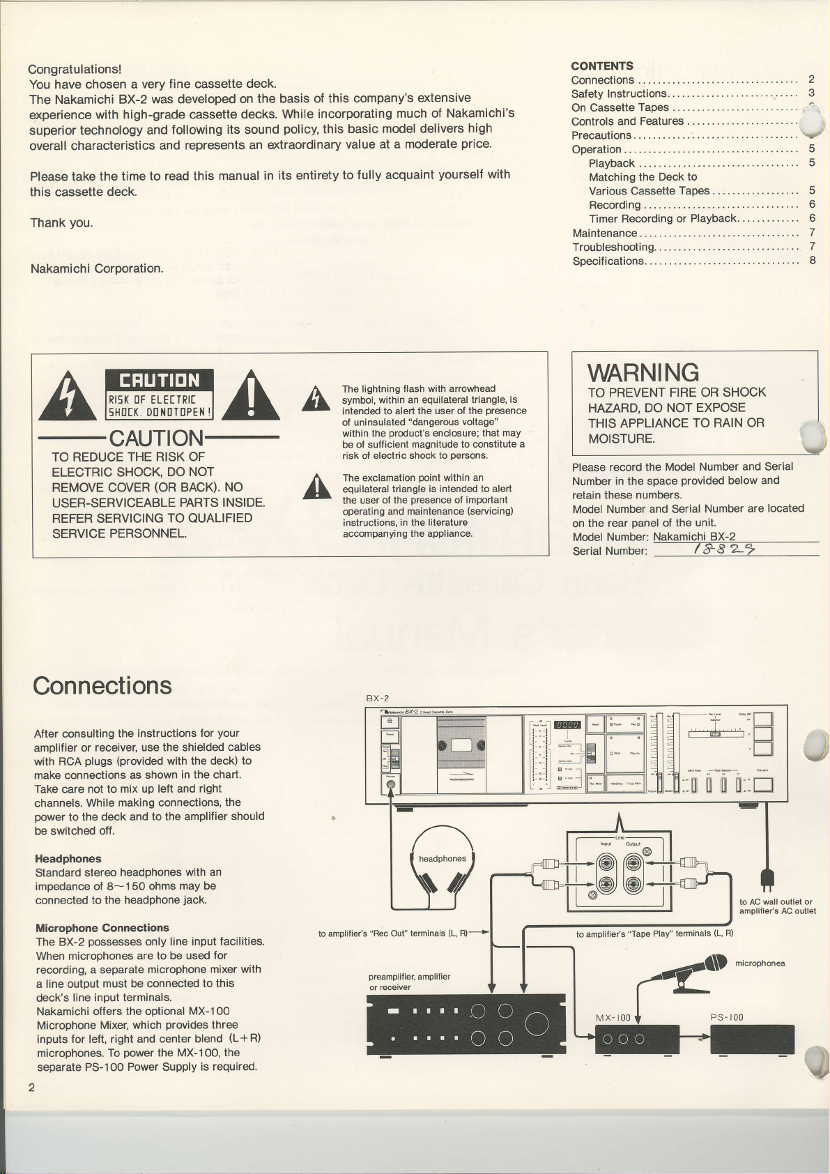
Connections
consulting
After
amplifier
with RCA
make connections
Take care not to
channels.
power
to
be switched off.
the instructions
or receiver, use
(provided
plugs
as shown
mix up left and
making connections,
While
the deck and
to the amplifier should
the shielded cables
with the deck)
in the chart.
I
AA
QUALIFIED
your
for
to
right
the
The lightning
symbol,
intended to alert
uninsulated
of
within
be of sufficient
risk of electric
The
equilateral triangle
user of the
the
operating
instructions,
accompanyi
flash with arrowhead
within an equilateral triangle,
the user of the
"dangerous
product's
the
magnitude to constitute a
shock to
exclamation
ooint
is intended to alert
presence
and maintenance
in the literature
ng
appliance.
the
voltage"
enclosure;
oersons.
within
an
of important
(servicing)
is
oresence
that may
WARNING
TO PREVENT
HAZARD,
APPLIANCE
THIS
MOISTURE.
Please record
Number
retain
Model
on
Model
Seriaf
in the space
these
Number and Serial
rear
the
Number:
Number:@
FIRE OR SHOCK
NOT EXPOSE
DO
the Model
provided
numbers.
panel
of the
Nakamichi BX-2
below
Number
OR
are
and
located
TO RAIN
Number and Serial
unit.
J
Headphones
Standard
impedance of 8- 1 50
connected
Microphone Connections
The BX-2
When microohones
recording, a separate
a line output
line input
deck's
Nakamichi offers
Microphone
for left, right and
inputs
microphones. To
separate PS-100
2
headphones
stereo
headphone
to the
possesses
are to be used
must be connected
terminals.
the ootional
Mixer, which
power
Power Supply
with an
may be
ohms
jack.
line input facilities.
only
microphone
center blend
the MX-1 O0,
to this
MX-1
provides
is required.
for
mixer with
00
three
(L+R)
the
amplifier's
to
"Rec
Out"
terminals
wall outlet or
to AC
amplifier's
AC outlet
(L,
to
amplilier's
"Tape
Play"
terminals
(L,
R)
Page 3
Safety
Instructions
r
following safety instructions
\r6luded in
regulations.
1. Read Instructions
operating instructions
before
2.
Retain
operating instructions
lor
3. Heed Warnings
appliance
should be adhered.
4.
Follow lnstructions
use instructions
Water
5.
should
example, near a bathtub, washbowl,
.
kitchen
,
arbasement,
6. Carts and
be used
recommended
7.
Wall or
should be mounted
as recommended
compliance with
Please read
the appliance is
instructions
future reference.
and in the operating instructions
and Moisture
not
be used
laundry
sink,
or near a swimming
Stands - The
only with a
Ceiling Mounting
them
-
All the
should
operated.
-
The
should be retained
-
All warnings
-
All operating
should
be followed.
-
The
near
water
tub, in a wet
cart or stand that is
by the manufacturer.
to a wall
by the manufacturer.
have
safety
carefully.
safety and
appliance should
-
been
standard
safety and
read
be
the
on
and
appliance
-
for
pool,
etc.
The appliance
or ceiling only
8. Ventilation
situated
does not interfere
ventilation.
should
or similar
ventilation
installation,
that
ventilation
9. Heat
away from
heat registers,
(including
1O.Power
connected
type
instructions
appliance.
1 l.Grounding
should be taken
polarization
defeatdd.
1 2.Power-Cord
cords
not likely
items
particular
convenience receptacles,
where
-
The
so that its location
not
surface that may
may impede
-
The
Sources - The
described in the
should be routed
to be walked
placed
attention
they exit from
appliance
with its
For
example, the
be situated
openings;
such as
the flow
openings.
appliance
heat
sources
stoves, or
amplifiers)
power
to
a
or as marked
or Polarization
so that
means
Protection
upon or against
should be
position
or
proper
appliance
on a bed,
block the
placed
or
a bookcase
of
air through
should be
such as radiators,
other appliances
produce
which
appliance
supply
only of
operating
on
the
-
Precautions
grounding
the
of an
appliance is not
-
Power-supply
so that they are
pinched
on or
them,
and
plugs,
the
to cords at
the appliance.
sofa, rug
in
a built-in
or cabinet
situated
heat.
should
the
by
paying
point
or
the
be
l3.Cleaning
cleaned
manufacturer.
'1
4.Nonuse Periods
appliance
outlet when
time.
1S.Object
taken
are not
openings.
16.Damage
appliance
service
A. The
B. Objects
C. The
D.
E.
lT.Servicing
to
described
other
qualified
-
only as recommended
should
and Liquid
so that
spilled into
Requiring
should be
personnel
power-supply
been damaged;
spilled into
rain;
The appliance
operate normally
change in
The appliance
enclosure
service
have fallen,
appliance
or,
the appliance
in the
servicing
service
The
appliance
be unplugged from
left
unused for a long
Entry
objects
when:
the
appliance;
has
does not
performance;
has
damaged
The
user'should
operating instruction.
should
personnel.
should be
power
The
-
Care should be
do not fall and liquids
the
enclosure through
Service
or,
-
serviced by
cord or the
liquid
or
been exposed to
appear to
or exhibits a marked
or,
been dropped,
beyond
be referred
by the
cord of the
period
The
qualified
plug
has been
or,
not
attempt
that
to
the
of
has
or the
All
On
Cassette
Precautions
1. C-120 cassettes
per
side) contain extremely thin tape
which breaks
1,
Vsometimes
is of low sensitivity.
cassettes are
high{idelity recording.
2. Do not
3. Be careful not to turn the
4. Store cassette tapes away
pull
housing.
with the fingers, causing
humidity,
as caused by
(playing
or snarls easily, is
subject to
Therefore,
not
recommended
out the tape from
dust, and magnetic fields
speakers, TV sets etc.
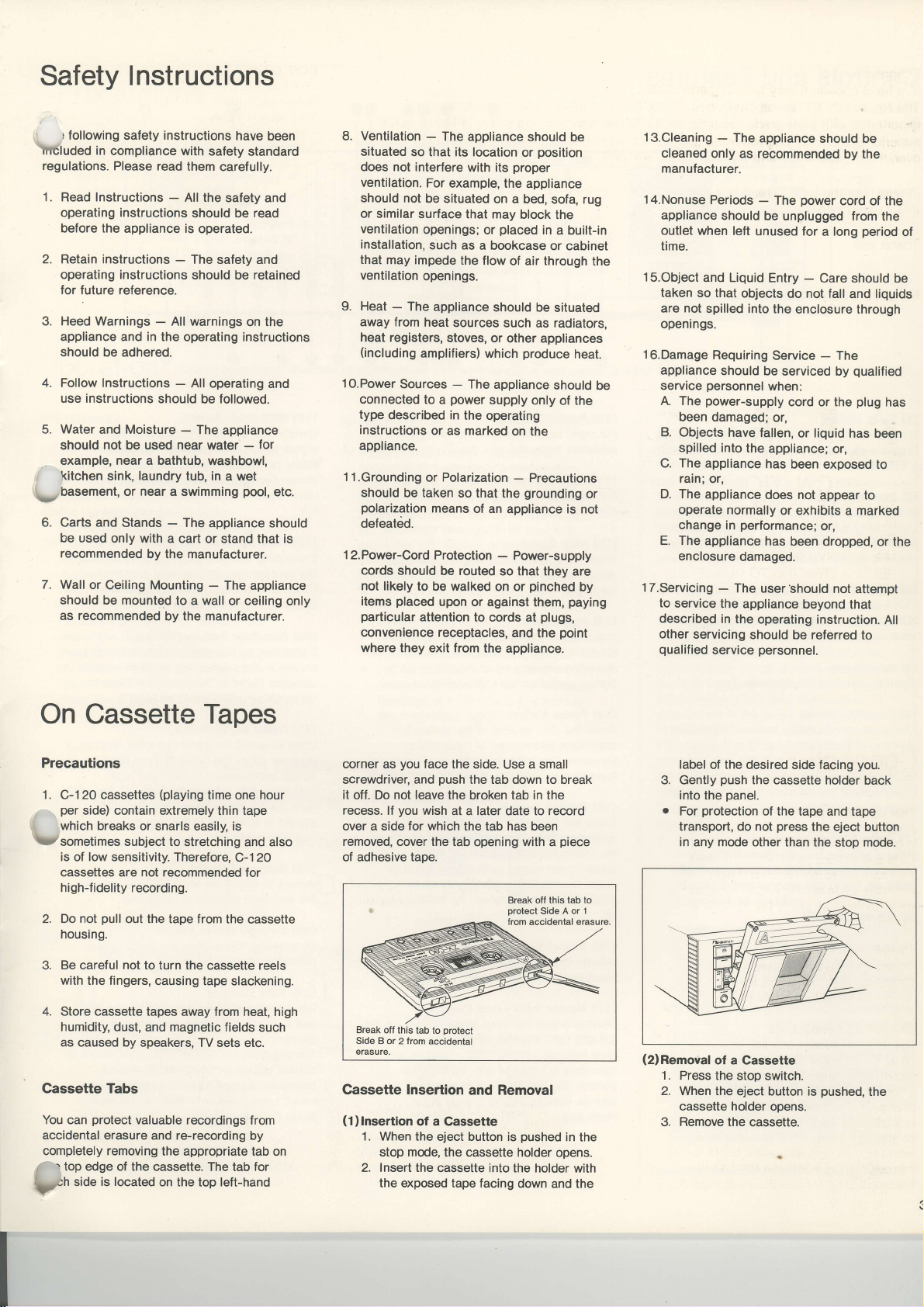
Cassette Tabs
You can
accidental erasure
completely removing
/
pn
protect
valuable
and re-recording
r
top edge of the cassette.
.io" is located
the appropriate tab
on the top left-hand
Tapes
time one
stretching and also
cassette reels
tape slackening.
recordings from
The tab for
hour
C-120
for
the cassette
from heat, high
such
by
on
corner as
screwdriver, and
it off.
recess.
over a side for which the tab has been
removed, cover the tab
of adhesive
Cassette Insertion
(1)lnsertion
you
face the
push
not leave
Do
you
lf
wish
tape.
Break
off this
Side B
erasure.
1. When
2. Insert the cassette
tab to
or 2 from accidental
of a Gassette
the eject button is
mode,
stop
the exposed tape facing
the tab down to break
the broken tab in the
at a
protect
and
the cassette holder
side. Use a small
later
date to record
opening with a
Break off this
protect
Side
trom accidental erasure
Removal
pushed
into the holder
down
piece
tab to
A or 1
in the
opens.
and
with
the
label
of the desired side facing
push
Gently
into
the
protection
For
transport, do not
in any mode
(2)Removal
1.
2. When
3. Remove the
of a Cassette
Press the stop
the eject button is
cassette holder opens.
the cassette
panel.
of the tape and tape
press
other than the
switch.
cassette.
you.
holder back
the eject button
stop
pushed,
mode.
the
Page 4

Controls and Features
(1)
Eiect Button
By depressing this button,
holder is opened for insertion and
a cassette.
(2)
Power Switch
Pressing this switch activates the deck.
Depressing
off. When the
switch indicator lights up.
(3)
This switch
automatic
odernal audio timer.
(4)
Accepts standard stereophone
(5)
The cover can be easily
cleaning of
(6)
Provide exact
range
(7)
When the Dolby B-Type NR or the Dolby
C-Type NR
lights up.
(8)
When this switch
the tape
fast-forward at the
indication. When the switch is set to
"Memory
fast-forwarded,
from the
(9)
By depressing this switch during recording,
the
During operation, the indicator lights up.
it
once
power
Timer
Switch
permits
playback
Headphone
Cassette
Peak LeYe! Meters
of
Dolby
Memory
Rec Mute Switch
input
Jack
Holder
heads s1s.
indication of
-30
dB to *5 dB.
NR lndicators
is
used,
Switch
is
is
stopped
Play" and
playback
"OOOO"
indicAtion.
signal can be temporarily cut off.
the cassette
removal
more
switches
is switched
unattended recording or
in
conjunction with an
removed for routine
(*p.
7)
peak
the respective indicator
"Memory
set to
from rewind or
"0000"
tape counter
the
is rewound
tape
automatically starts
power
the
on, the stop
plug.
levels in the
Stop",
or
(1O)
Rewind
Switch
For rapid tape
of
direction,
(1
1) Fast-Forward Switch
For rapid tape
direction,
(1
2)
Stop
the D section is
When
motion comes to a full stop and the indicator
lights up.
(13)
Play Switch
Press the
playback.
recording-standby mode, recording starts.
During operation,
(14)
Pause Switch
Press the
short-term
playback.
recording
(15)
Record Switch
Press the O section of the switch for
recording. This deck
recording-standby feature.
pressing
mode, the recording-standby mode is
entered. During operation, the indicator lights
&
uo.
(16)
Output Level
Adjusts
headphones listening
(17)
Master
to adjust the input
Used
left
and
level
balance between
recording
control. The
also be used to fade in
recording.
winding in
press
the
winding
press
the
Switch
>
section
When the switch is
section
EE
interruption
The indicator
playback, press
or
the record switch from the
the line
output
lnput
right
channel simultaneously. The
is adjusted with the balance
master
the reverse
<<
section
in the forward
>>
section of the switch.
pressed,
the
of
switch
pressed
the indicator lights up.
the
of
switch
recording
of
lights up. To resume
the
possesses
By simply
Control
level
and the
level.
Level Control
(record)
channels in
both
inout level control can
fade
or
out
of the
switch.
the tape
to
start
in the
for
or
play
switch.
a one-touch
stop
level for the
a
(18)
MPX Filter
to cut the 19-kHz multiplex carrier
Used
which
signal,
Dolby NR system when recording from FM
stereo broadcasts. When recording from
other sources, this switch
off.
(19)
Tape Selector Switches
Depending on the tape used for recording,
the appropriate
Refer to
Cassette
(2O)
Equalizer Switch
Depending on the tape used
playback,
selected.
Various Cassette Tapes" on
(21)
Dolby NR Switches
to select the
Used
desired: either
1o-dB improvement
frequency
for a
20-dB
is
system
indicator lights up.
(22)
Balance Control
to
Serves
left and right
(23)
Gounter
pressing
By
indication is reset
(24)
Tape Counter
be used to
Can
and to check
moment.
Starting from the
carried out
playback
count") and
("minus
mode
Switch
could cause
position
"Matching
Tapes" on
the appropriate
Reler to
the
ratio
S/N
improvement. lf a Dolby NR
the respective
used,
the level
adjust
channel
Reset
this switch, the tape counter
index
the tape's
"0000"
"9999"
up to
fastJorward
and
down to
count").
misoperation
should
must
the Deck to Various
page
"Matching
noise
Dolby B-Type
in midor
"0000".
to
"-999"
be selected.
5.
for recording
position
the Deck to
page
reduction system,
and
the Dolby G-Type NR
Dolby
balance
in recording.
Switch
sections on the
position
indication, count is
in
the
modes
in the rewind
be set to
must be
5.
NR for a
high-
between
given
at a
record,
("plus
of
NR
tape
the
or
if
J
il
V
a
Page 5

Precautions
1)
After the
on, the tape
Inoperative
circuits
(2)
After timer recording
completed,
operative. To eject
case,
OpefatiOn
power
control buttons
for
appr.4
have become
the eject
press
not
do
to the deck is
stable.
or timer
button may not
the tape
the
switched
are
seconds,
playback
in such
button forcibly.
Gheck once more whether
lPlaybackl
(1)
Confirm that the
-
Switch on
jassette
\zholder.
(2)
Set the equalizer
appropriate
(3)
lf
the tape to
recorded
reduction,
Dolby NR switches.
recorded
reduction,
respective
lf the tape to
recorded
press
(4)
the
Press
the > section
lMatching
Tape
Selector Switch and Eq Switch Settings
:)U120
pS
I
-E-
EX
I
SX,/TO&S
Tape
_T,^6
timer switch is
power
the
played
to be
switch to
position
played
be
with
Dolby
press
the
with Dolby
press
the
Dolby
NR indicator
played
be
with
Dolby noise
"Off"
switch.
and insert
into the
for
C-Type noise
"C"
lf the
B-Type noise
"B"
of the
set to
the
cassette
the
the tape in
back was
switch
of the
tape was
switch.
The
lights
back was
reduction,
play
switch.
the Deck to Various
Position
Tape
Position
Selector
IL
SX
q6t6^+^r_
IL
zx
Switch Eq
not
ItAIL
EX
SX
ZX
until all
(3)
is
be
a
Set
all connections
(5)
Off.
use.
up.
(6)
Gassette Tapesl
(Recommended
Switch
Eq(rrsec)
I
.EL
70
the
timer switch to
switch to
and the tape
Voltage
AC voltage
which
selector
in
Adjust
level control.
When the tape
auto-shutoff
stops the tape transport.
remove
press
For temporary interruption
press
switch. To
play
o
.
On. The button is
Selector
you purchased
permits
case the
the desired volume
the tape
the E section
the
EE
resume
switch
The logic-controlled
permits
deck
mode into
rewind,
from rewind
etc.) without
playback
During
display the level
Readings are
the
output
Off, and the
can be removed.
is factory-set
re-setting
deck
between
end is reached,
mechanism
during
section
again.
going
any
using
not affected
level
for the
your
is
to be used
amplifier
automatically
lf
playback,
of the
of the
playback, press
transport
from
(i.e.
other
to
the
peak
the
recorded
control.
Tapes)
Nakamichi
Nakamichi EX
TDK AD,
MaxeII
Fuji FR-l
AMPEX GM-I
Nakamichi
TDK
Maxell
Fuji
AMPEX GM-II
Brand Name
power
now
operative
country in
BX-2. The voltage
of mains
in a
voltage
different
and cassette deck have been
with
the output
the
you
want
to
first
stop switch.
playback,
of
pause
the
of this
any
transport
play
from
fast-forward,
stop switch.
EX
UD,
SX
SA-X
UD-XU, XL-[S
FR-ll
to
level meters
on
the tape.
by
turning
II
AD-X
XL-IS
UD-XLI,
counlry.
Note:
Safety regulations in
prohibit
inclusion
feature, therefore, may
deck.
certain countries
of a
_
120V
@m@
220_24OV
properly
I
Memory
By setting the memory
playback
Play",
"00O0"
the
tape is
setting the
motion during rewind
automatically
point
I
Dolby
This
B-Type
reduction
selected. The
approximately
the
NR
appr.2O
kHz,
For
recorded
NR
playback
C-Type
presseo.
.
The
any noise
source signal.
noise-free as
tape counter
rewound
switch to
is
reached.
NR
deck incorporates
and the
systems, which
high frequencies.
achieves
"B"
use recording
in
dB
where noise is most
playback
with Dolby
switch has
of a tape recorded
NR, the
Dolby NR system
estabtished.
Switch
automatically
fast-torwarded.
or
"Memory
stops when the
System
Dolby C-Type noise
Dolby B-Type
1O dB
of noise reduction
ratio
a S/N
the range
of a tape which
B-Type NR,
to be
"C"
switch must
already
You should
sources
oossible.
voltage
selector.
be absent from
1
switch
fast-forward
or
both the
The
contained in
"Memory
to
starts from
point
when
Stop", tape
"0000"
Dolby
can be freely
provides
NR
Dolby C-Type
improvement
from 2 kHz
readily
audible.
was
the Dolby
pressed.
with
Dolby
be
does not
therefore
which
are as
the
By
of
to
For
reduce
the
This
your
in
8
.
This
results
EX
a
.lttnese
ape
Selector
.u-
EX
cassette deck will
trcassette
tapes whenever
SX
with
Nakamichi ZX,
tapes.
l
-Ezx
achieve
Therefore the use
possible
best
SX and
is
Nakamichi
TDK
ilaxell
Fuji FR-Metal
AMPEX
recommended.
lf
of
other tapes are used, it is
to choose tapes from
ZX
MA,
MX
MPT
this list.
MA-R
desirable
Frequency Response
and
Ff*ncy
(Hz)
Noise
Spectrum
Analysis
Page 6

lRecordingl
(1)
Confirm
Switch
cassette
cassette
(2)
Set
equalizer switch
Cassette
(3)
switches.
(4)
(5)
(6)
(7)
(8)
that the timer switch
power
on the
to
be
and insert the
used for recording
holder.
the tape
use.
selector switches and
"Matching
(*
according
the Deck
Tapes")
NR is to be
lf the Dolby
press
used,
respective Dolby
lf no Dolby
press
When recording
the MPX filter switch
Pressing
the tape counter
convenient
point
C-Type
"C"
the
lf the Dolby
press
the
switch
"8"
the Dolby NR
of
B-Type
switch.
NR indicator lights up.
noise reduction
"Off"
the
switch.
from FM broadcasts,
to On.
the counter reset switch
indication to
to easily re-locate the starting
the recording or
of
Play feature.
pressing
By
switch,
the recording-standby
The red O
and the
the O section of the
the deck
automatically
(Rec/Pause)
indicator in the record switch
green
indicator in the
0E
switch light up.
peak
While watching
adjust the
up the master
sliding
and adjusting
balance
For hints on
paragraph
the
When the > section of
pressed,
When the
auto-shutoff
stops the
you
lf
want to
recording,
switch.
stop
For temporary
press
the
switch.
play
switch again.
.
pressing
By
switch
record switch depressed,
the
the
recording level by
input level control
the left/right channel
with the balance control.
proper
level
"Record
Level Setting".
the
recording starts.
tape end is reached, the
mechanism automatically
tape transport.
remove the tape during
press
first
the
interruption of recording,
section of
!!
resume recording,
To
the > section of the
while keeping the O section of
recording can be started immediately
entering the standby mode.
without
.
lf the record switch
play
the
cannot
switch, the
be entered.
is
recording mode
is set to Off.
into the
the
to the tape
in
to Various
used,
NR is to be
The
used,
is to be
set
to bring
"0000"
is
use the Memory
record
goes
into
mode.
pause
level meters,
gradually
settings,
tr
the
refer to
play
switch is
section of
pause
press
the
the
play
pressed
after
I
By
recording,
record
off and the
the switch
can
tape, etc.
Mute
Rec
pressing
the tape
mode,
be used to
The line output
the Rec Mute switch
but the
indicator
is being
headphone output
this operation,
continuously
I Record
This deck's
"overshoot"
levels with a
"Chrome"
Adjust record
lights up only
oeaks.
[Timer
This
deck
which enables
monitor the
Level Setting
LED
problems
high degree
(LH)
position
position
levels so that the + 3 dB
occasionally on
Recording or
incorporates
you
recordings or start
selected
time with the use of a
continues to
run in the
input signal is cut
lights for as long as
kept depressed.
insert blank spaces
and the
muted during
are not
possible
it is
so that
input
signal.
level meters are
and display
of accuracy.
tape formulations,
tape fotmulations:
the highest signal
I
'-
|
le
I l- r
lr
r_
I
LI
_!-.
I t-.
I :-
l!-.-! |
lr
trlr ^^ I I
lt-4-t I
l! ^^ I I
-*
"
-
-I
_r I
-!-
-!
"
-:
-r
;l
rl
IJ
I
I
|
I
|
I
I
I
_-.l
*dB
r_
P€k Level
lr-w-r I
l' " I
LdBJ
As dilferent tape
different
the requirements
when using ditferent
Playback]
a timer-start feature,
to make unattended
playback
at a
timer.
pre-
during
This
on a
to
free of
peak
indication
overload
good
For
recordings,
maintain a high signal-to-noise
record level
impair the
is set too low tape
playback
other hand, setting
high will cause distortion.
guideline
chart below as
recording
The
Dolby C-Type
in this deck
prevent
to
saturation
levels can be set
without noise
"Metal"
record levels
Adjust
lights
up
oeaks.
a
levels.
possesses
distortion even at
levels. Therefore recording
in
reduction.
position
tape formulations:
only occasionally
so that the + 5
_
I
I
lr
Li
tapes.
(1)
Establish
chart.
(2)
Insert the tape
playback
components.
(3)
For
level to suit the
playback,
desired
set
(4)
For timer
switch
the
(5)
Set
(6)
At the
supply
deck
playing.
.
have slightly
characteristicq
degree
connections
and turn on
timer recording, set
the output control
set
level. Check
properly.
up
recording, set
"Rec".
to
switch to
the timer
"Play".
to the desired operation
pre-selected
power
to the
will automatically
Be sure to
"Off",
to
playback
set the deck's timer switch
when
feature is
tormulations
(headroom)
may vary to a certain
it is essential to
ratio. lf the
hiss will
quality.
sound
the record
On the
level too
Refer to the
to set
NR system
incorporated
advanced circuitry
high
the same
Peak Level
r_ q _t
!- e -l
|
tr
- -!_i
l-
rl - -!-r
lr c I I
ll
lr-
l!-,.-! |
lr I I
tr-
wav as
the highest signal
on
_-l
*dB
I
I
-
ll
I
rl
-l
n
-
I
I
-r
I
-r
I
dB indication
l!-^-! |
l!-*-! I
Ir a I
L
to be used
--l
dB
as shown
in the
for recording or-
power
the
to all
the recording
expected signal. For
to the
if
components
all
this deck's timer
time,
playback,
the timer will
For timer
components, and
start recording
the timer recording or
not
desired.
timer
are
set
time.
the
or
I
Page 7

Maintenance
'
d and Transport Cleaning
very important to regularily
\/
surfaces of the heads as well as the
capstan,
pinchroller
and all other
which come in contact with the tape. Tiny
particles
oarts,
shedded
as well as dust accumulations etc.
from
the tape onto these
become the cause of drop-outs, and severely
degrade frequency response and
wow-andJl utter characteristics.
Gleaning Procedure
Remove the
cassette
holder
cover. Use
cotton{ipped sticks or the like
audio
stores, etc.) to carefully and
light
white
pressure
on
clean the
the illustration. In
parts
cases of severe
contamination, dip the cotton tip in cleaning
fluid.
Cleaning
is facilitated if
removing the cassette holder
cover is closed again and the
depressed, thereby raising the head
---embly.
pressure
b
switch and clean the roller while it is
lry
roller is very dirty,
turning. At this time, be careful that the
cotton
tip does not
get
caught
roller and the capstan. After cleaning the
roller,
put
the deck
into
the
pause
again and clean the revolving capstan.
the
clean
parts
(available
with very
indicated
-
after
cover - the
pause
switch
press
between
mode
in
in
the
the
Erase Head
Guide Tape
Tape
Be careful not to
cleaning as the respective
Rec/PB Head
Guide
CaDstan
Pressure Roller
apply too much force in
parts
are
critically aligned. Take special care not to
damage the tape
Do not
use too much cleaning fluid and
give
the cleaned
dry off completely
you
When
be careful
on the cleaned
guides.
surfaces some time to
playing
before
have
used cotton-tipped
not
to leave any cotton strands
parts.
a tape.
sticks,
Demagnetizing
After a longer
build-up
capstan, etc.
induce noise
during
demagnetize these
hours of use with
50
period
residual
of
of use, there can be a
magnetism in heads and
residual
Such
magnetism can
and impair the high frequencies
playback.
prevent
To
parts
this,
about once
the optional Nakamichi
DM-10 Demagnetizer or another
designed demagnetizer.
demagnetizing
procedure,
demagnetizer's instruction
.
Always switch
For details on the
please
manual.
power
off the
before starting the demagnetizing
orocedure.
Gleaning
This unit
with a
solvents, ammonia
the
Faceplate
should be cleaned only by wiping it
soft, dry cloth. Never use alcohol,
or abrasive cleaning
agents.
Lubrication
All important moving
fitted
with long-life,
lubrication is
parts
this deck
of
oil-less bearings.
therefore not necessarv.
you
should
every
properly
consult the
to the deck
are
Periodic
Troubleshooting
Condition Probable
Taoe
qecord
\z
EX
Uneven
excessive wow/flutter.
Incomplete
Distorted record/playback
Record mode is entered,
recoro.
Cannot
Dull high lrequencies
Hum heard
not run.
dose
mode cannot
playback
cessive
sound levels, drop-outs,
erasure.
playback
during
be enteJed. 2.
hiss.
sound. 7.
but cannot
recording
playback.
or
'1.
3. Head
4.
5.
6.
8.
9.
lO. Wrong setting of tape selector switches.
| 1.
1 2. Head dirty.
1 3. Output disconnected.
14. Head dirty.
1
5.
16.
17. Strong
1 8. Signal
Cause
holder not
Cassette
tabs have been removed.
Cassette
is magnetized.
Heads and/or capstan and
Faulty cassette.
Erase head
Program material itsell is distorted.
Recording levels are too high.
Head dirty.
Input
disconnected.
dirty.
Head
Tape selector switches
correclly.
induction
cable
comoletelv
dtry.
fields near deck.
or connector
locked.
pressure
and/or equalizer switch not set
grounding
roller dirty.
laulty
Remedy
'1.
Press eiect button and then close cassette holder firmly
Place
2.
adhesive tape over tab opening or use new
cassette.I
Demagnetize head.
3.
4. Clean these oarts.
5. Reolace cassetle.
Clean head and
6.
7. Check
8.
9. Clean
'lO.
1.
1
1 2. Clean head.
13. Check connections.
14. Clean head.
1
5. Clean
16. Select correct
1 7. Keep deck away
18.
program
Wide dynamic range
but excessive
Adjust recording levels.
head.
Select correct setting for the tape in use.
Check
head.
lamos. etc.
Replace
material.
recording levels will cause
connections.
positions
signal cables.
roller
oressure
permits
some short-term overload,
for tape in use.
from
amplifier, transformers, fluorescenl
distortion.
Page 8

Specif
ications
Specifications
TrackConfiguration..
Heads..
(Tape
Motors
Power Source.
Power
Tape
Wow-and-Flutter.....
Frequency Response .......2O
Signal-to-Noise Ratio .......
Total Harmonic
Erasure
Separation
Crosstalk
Bias Frequency... .. ..
Input
Output
Dimensions
Approximate Weight . .......5.5
Transport)
Consumption... ......23
Speed.
Distortion. . .
(Line)
(Line).
(Headphones)
.......4tracks/2-channelstereo
.....2
... .
DC servo motor
DC motor
.. .
1O0,
(According
1-718 ips.
.......
Less than
Less
Dolby
Better
Dolby B-Type
Better than 62dB
Less than
Less than
.. . . .
Better than
..
Better than
... Better
. ... . .
1 05
.50 mV
.......
O.sV
.. .
... .2.2 mW
.490(W x
16-15/16(W) x
12lb.2 oz
(erase
head x
1, record/playback head x 1)
(capstan
(reel
to
country of sale)
(4.8
cm/sec.)
0.1't%
0.06"/0
68dB
1.O%
1.2"/o
60
36
dB
60
kO
30
Hz, 0 dB,
(400
Hz, O dB,
110(H) x
drive) x 1
WTD Peak
WTD RMS
(recording
<70ps,
(400
Hz,
(70ps,
NR on
(400
Hz,
(400
Hz, 0 dB, ZX,
Hz, 0 dB,
@OO
(1
dB
00
(1
dB
kHz,
(1
kHz,
output
output
2s0(D)
4-5116(H) x
'12O,12O/22O-24O,22O
W max.
than
HZ-20,OO0 Hz
C-Type NR on
than
than
kHz
(400
kg
drive) x 1
or 24OY AC;
io.S%
-2O
level
ZX tape>
THD, IHF A-WTD RMS)
3%
ZX tape>
THD, IHF A-WTD
3%
II
EX
tape)
SX
Hz, 0 dB)
dB)
0
0 dB)
level
control at max.) 2.2 kO
level
control at max.) 8 O load
miilimeters
9-7l8(D)
inches
50/60H2
dB)
tape)
RMS)
Optional Accessories
ZX
Gassette
SX
Cassette
EX II
EX
Gassette Tape
DM-1 O Head Demagnetizer
SP-7
Tape
Tape
Cassette Tape
Headphones
Stereo
C-60, C-9O
C-60,
C-90
C-60, C-9O
C-60, C-90
Specifications
notice.
a
Dolby NR
a
The word
Corporation.
Nakamichi
Tokyo
Office
Shinjuku Daiichi Seimei
2-7-1
Nishishiniuku,
(03)342-21461
Phone :
f elex'. 2324721
0D041 007
and appearance
under license
"DOLBY"
Corporation
Shiniuku-ku, Tokyo
(NAKAM
design are subject to
from Dolby Laboratories
and the Double-D-Symbol
Bldg.
J)
change for further improvement without
Licensing
are trademarks
Nakamichi
1101
Santa Monica.
Phone
Telex :
Corporation.
of Dolby Laboratories Licensing
U.SA.
Colorado Avenue
Calif. 904O1
(213)
:
451-5901
(NAKREI
652429
Corporatio
SNM
n
)
Nakamichi
220
Westbury
Carle Place,
(516)
Phone:
U.SA.
Avenue
N.Y.
333-5440
Corporation
11514
I
\J
in Japan
G8209308
Printed
 Loading...