

Page 1
MAXDATA PLATINUM 3200 I – Quick Start Guide
B
A
G
F
D
E
C
A B D
G
FEC
I
H
J
L
K
M
Q
N
O
P
U
R
S
T
X
CC
EE
FF
BB
DD
AA
Z
Y
W
V
NN
OO
PP
SS
QQ
RR
MM
LL
KK
JJ
II
HH
GG
DIMM A2
DIMM A1
DIMM B2
DIMM B1
DIMM C2
DIMM C1
DIMM F1
DIMM F2
DIMM E1
DIMM E2
DIMM D1
DIMM D2
Thank you for buying a MAXDATA PLATINUM 3200 I Server. This document describes how to set up
the system, turn on the system, and complete configuration for the system.
Follow the link “User-Support und Treiber” on www.maxdata.de to access the download area and download a more detailed guide.
Safety
Warning
Installation and service
Installation and service of this product is to be performed only by qualified service
personnel to avoid risk of injury from electrical shock or energy hazard.
Enclosure cover
In order to comply with applicable safety, emission, and thermal requirements, no covers
should be removed and all bays must be fitted with drive carriers.
Battery Safety
There is a danger of explosion if the battery is incorrectly replaced.
Dispose of used batteries in accordance with the manufacturer’s instructions and national
regulations.
Caution
Electrostatic discharge
Observe normal Electrostatic Discharge (ESD) procedures during system integration
to avoid possible damage to the server board and/or other components of the server
system.
Server system power
System power on/off: The power button DOES NOT turn off the system AC power. To
remove power from server system, you must unplug the AC power cord from the wall
outlet or the chassis.
Site Selection
The system is designed to operate in a typical office environment. Choose a site that is:
• Clean, dry, and free of airborne particles (other than normal room dust).
• Well-ventilated and away from sources of heat including direct sunlight and radiators.
• Away from sources of vibration or physical shock.
• Isolated from strong electromagnetic fields produced by electrical devices.
• In regions that are susceptible to electrical storms, we recommend you plug your system into a
surge suppresser and disconnect telecommunication lines to your modem during an electrical
storm.
• Provided with a properly grounded wall outlet.
• Provided with sufficient space to access the power supply cord(s), because they serve as the
product’s main power disconnect.
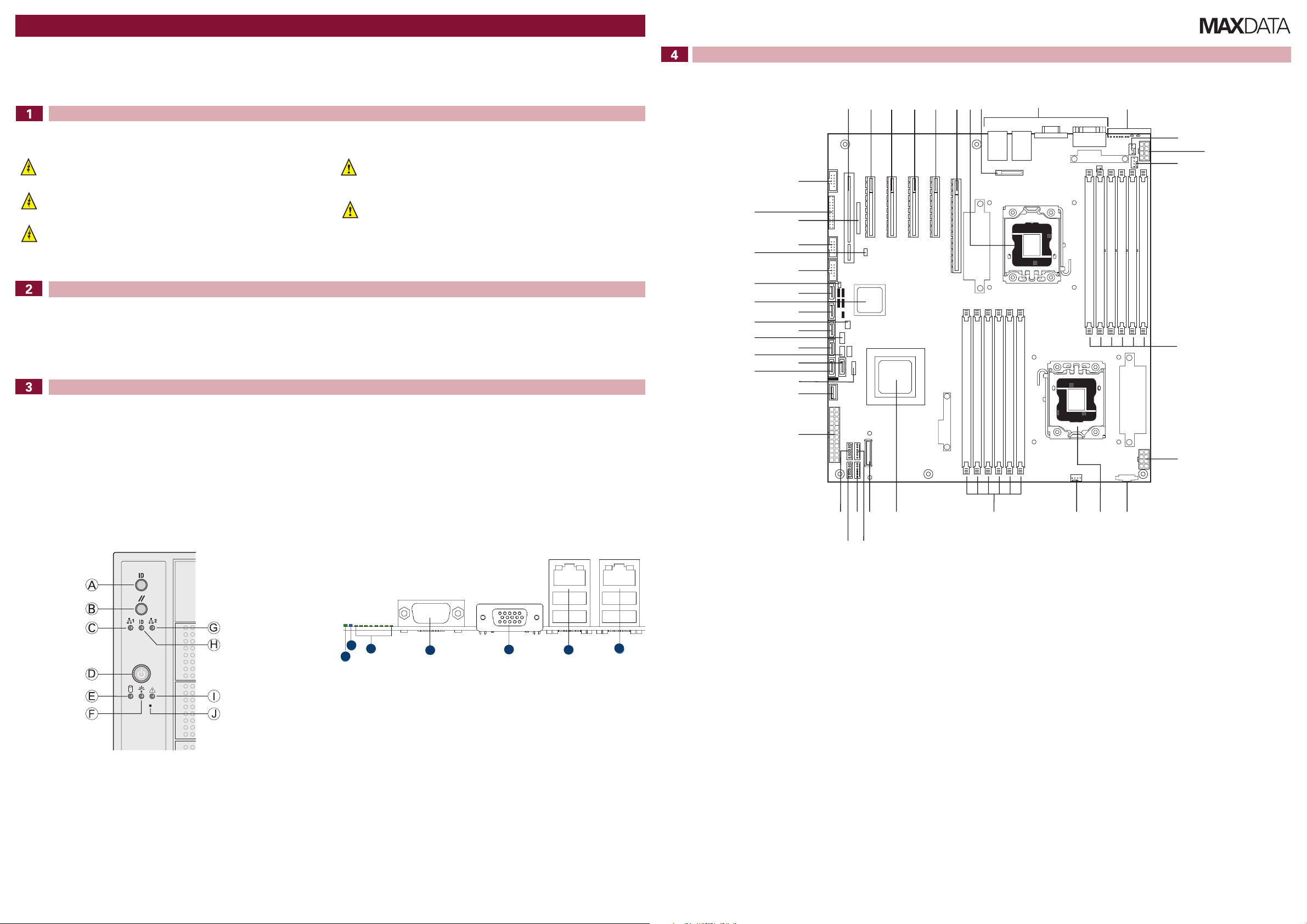
Server Board Connector and Component Locations
System Overview
Technical Specification
Dimensions (upright configuration):
- 432 mm high
- 218 mm wide
- 709 mm deep
- 36 kg max. weight
System Power:
- Redundant Power Supply (two line connectors, one for each power module)
100-127 V / 200-240 V at 50/60 Hz; 12 A / 6 A max.
- Single Power Supply
100-127 V / 200-240 V at 50/60 Hz; 12 A / 7 A max.
Temperature Range: +10 °C to +30 °C
Front Controls
A. ID Toggle Switch F. Power/Sleep LED (green)
B. Reset Button G. NIC 2 Activity LED (green)
C. NIC 1 Activity LED (green) H. ID LED (blue)
D. Power Button I. Status LED (bi-color)
E. Hard Dri ve Activity LED (green) J. NMI Button
Regulatory Compliance
This product complies to the following requirements:
- EN 60950 – Safety
- EN 55022 – Emissions
- EN 55024 – Immunity
- EN 61000-3-2 – Harmonics
- EN 61000-3-3 – Voltage Flicker
- CE – EMC Directive 89/336/EEC
This product has a CE declaration of conformity (CENELEC Europe).
This server system is compliant to European Directive 2002/95/EC (RoHS).
Back Panel Connectors
A. Status LED E. Video Port
B. System Identification LED F. NIC 1 (top, default management port),
C. Diagnostic LEDs G. NIC 2 (top), two USB ports (bottom)
D. Serial Port A
two USB ports (bottom)
A. Slot 1 (PCI, 32-bit, 33 MHz) P. Aux Power Signal EE. HSBP B
B. Slot 2 (PCIe x4) Q. CPU 2 Socket FF. SATA 2
C. Slot 3 (PCIe2 x8) R. CPU 2 Fan GG. HSBP A
D. Slot 4 (PCIe2 x8) S. DIMM Sockets (CPU 2) HH. SATA 3
E. Slot 5 (PCIe2 x8) T. IOH II. SATA RAID 5 Key
F. Slot 6 (PCIe2 x8) U. SAS Module Slot JJ. SATA 4
G. CPU 1 Socket V. System Fan 3 KK. ICH10
H. CMOS Battery W. System Fan 4 LL. SATA 5
I. I/O Ports X. System Fan 2 MM. HDD Activity LED
J. Diagnostic LEDs Y. System Fan 1 NN. USB
K. System Fan 5 Z. Main Power OO. USB SSD
L. CPU 1 Power AA. Type A USB Port PP. USB
M. CPU 1 Fan BB. LCP/IPMB Header QQ. RMM3 Slot
N. DIMM Sockets (CPU 1) CC. SATA 1 RR. Front Panel Header
O. CPU 2 Power DD. SATA 0 SS. Serial Port B
MAXDATA PLATINUM 3200 I M7 Quick Start Guide
Page 2
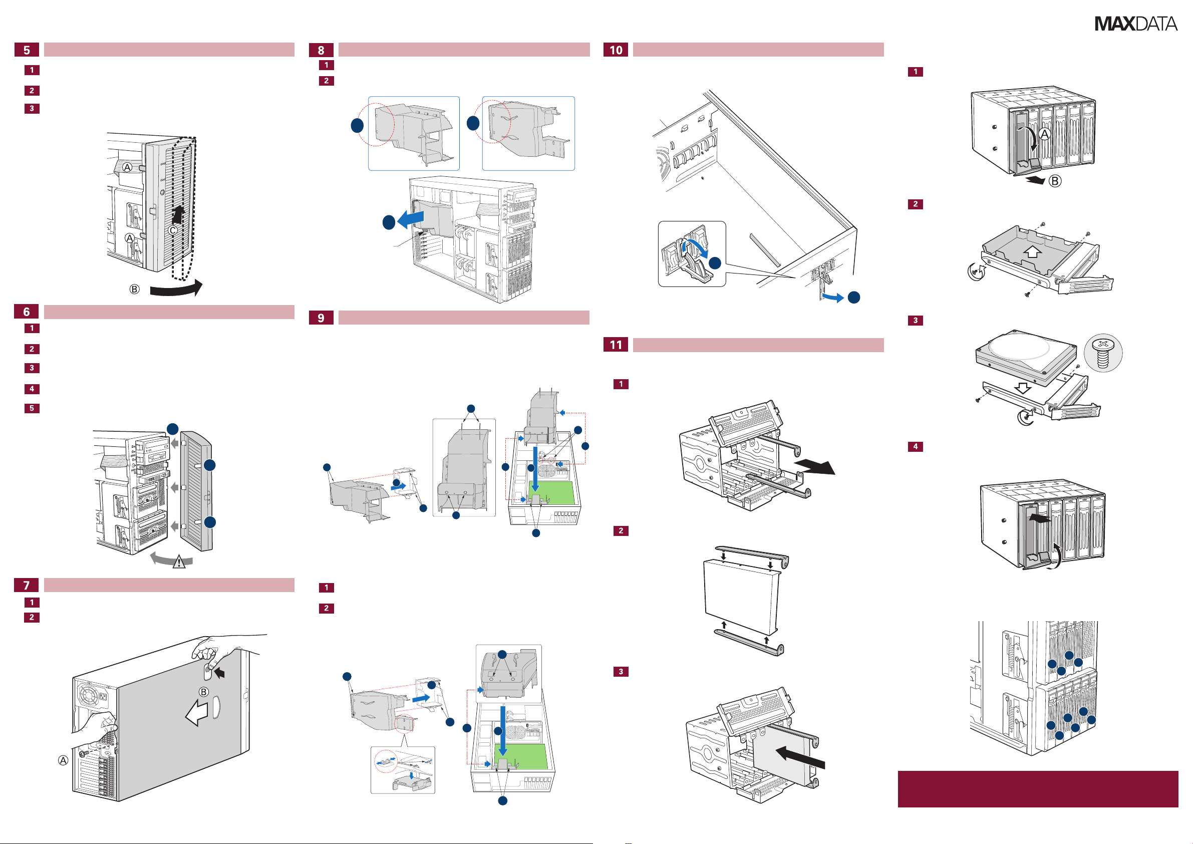
Removing the Front Bezel Assembly
40° max
B
A
B
A
B
B
P3200 Redundant P3200 Base
A
A
A
D
H
C
B
G
E
E
H
F
A
B
E
C
C
D
D
5
6
7
2
3
1
0
4
8
9
Release the two plastic tabs (letter “A”) on the left side of the bezel assembly to disengage
the tabs.
Rotate the bezel assembly (letter “B”) no more than 40 degrees outward.
Push the bezel assembly away from the chassis (letter “C”). If the bezel assembly does
not immediately disconnect from the chassis, tap the lefthand side of the bezel assembly
to disengage the bezel hooks on the righthand side of the chassis.
Removing the Processor Air Duct
Push the clips on the rear side of the air duct to loosen it from the chassis (letter “A”).
Slide the air duct out of the chassis (letter “B”).
Air Duct Latch
Installing and Removing a PCI Add-in Card
From inside, open the latch on the blue PCI card socket at the rear of the chassis. The PCI
card can now be installed or removed.
Hot-swap hard drives
Remove the drive carrier from the server chassis.
Remove the air baffle.
Installing the Front Bezel Assembly
Replace the external bezel assembly door.
Align the right-hand edge of the bezel assembly with the right-hand side of the server
chassis.
Insert the plastic hooks on the bezel assembly (letter “A”) into the slots at the edge of
the chassis.
Pull the bezel assembly toward the chassis.
Allow both plastic clips (letter “B”) on the left-hand side of the bezel assembly to click
into place on the chassis.
Removing the Server System Cover
If the shipping screw is installed, remove it (letter “A”).
Press the latch (letter “B”) and slide the top cover toward the rear of the server.
Installing the Processor Air Duct
P3200 I Redundant
Align the air duct with the rails on the rear chassis fan socket (letter “E”). Insert the air
duct clips (letters “B”, “C” and “F”) into the corresponding slots on the chassis (letters
“A”, “D” and “F”).
P3200 I Base
If two processors are installed, remove the plastic plate in the air duct (see enlarged
section, bottom left in the figure).
Align the air duct with the rails (letter “C”) on the rear chassis fan socket (letter “D”).
Insert the air duct clips (letter “B”) into the corresponding slots on the rear chassis fan
socket (letter “A”).
Mount the hard drive.
Installing Hard Drives
Non-hot-swap hard drives
Open the drive cage and remove the device slides.
Install the drive carrier.
Connect the device slides to the hard drive. The power connector is located at the rear.
Hard drive numbering
Slide the unit into the drive cage and connect the power and data cables to the hard
drive.
MAXDATA PLATINUM 3200 I M7 Quick Start Guide
Caution
Any empty drive bays must be occupied by carriers with baffles to maintain proper system
cooling.
To avoid possible damage to your chassis, use only carriers that came with your server system.
 Loading...