

Page 1

MAXDATA PLATINUM 100 Server
System Manual
1MAXDATA PLATINUM 100 Server
Page 2

2 Contents 3MAXDATA PLATINUM 100 Server
Page 3

Contents
1 Setting up the system..................................................................................... 7
Server position......................................................................................................................... 7
Connecting the system............................................................................................................ 8
Rear Connectors ................................................................................................................. 8
Powering up the system.......................................................................................................... 8
2 Description.......................................................................................................9
Server Board Features ............................................................................................................. 9
Server Board Connector and Component Locations.............................................................. 10
Processors ............................................................................................................................. 11
Memory ................................................................................................................................. 11
Intel® 845E Chipset................................................................................................................ 12
Intel® 82845E Memory Controller Hub (MCH) .................................................................. 12
Intel® 82801BA I/O Controller Hub (ICH2)......................................................................... 12
Intel® 82802AB Firmware Hub (FWH) ................................................................................... 12
I/O Controller ......................................................................................................................... 13
Serial Ports............................................................................................................................. 13
Parallel Port............................................................................................................................ 13
Diskette Drive Controller........................................................................................................ 13
Keyboard and Mouse Interface.............................................................................................. 13
Hardware Management Subsystem...................................................................................... 14
Hardware Management ASIC ........................................................................................... 14
Fan Monitoring .................................................................................................................. 14
Real-Time Clock, CMOS SRAM, and Battery......................................................................... 14
Legacy USB Support.............................................................................................................. 15
IDE Support ........................................................................................................................... 16
IDE Interfaces ................................................................................................................... 16
BIOS ...................................................................................................................................... 16
PCI Auto Configuration...................................................................................................... 16
PCI IDE Support ................................................................................................................ 17
Language Support ............................................................................................................. 17
Custom Splash Screen...................................................................................................... 17
Boot Options.......................................................................................................................... 17
CD-ROM and Network Boot ............................................................................................. 17
Booting Without Attached Devices................................................................................... 18
Fast Booting Systems with Intel® Rapid BIOS Boot .............................................................. 18
Intel® Rapid BIOS Boot...................................................................................................... 18
BIOS Security Passwords...................................................................................................... 18
System Management BIOS (SMBIOS).................................................................................. 19
Power Management Features ............................................................................................... 19
Wake on LAN Technology ..................................................................................................... 20
Wake on Ring ........................................................................................................................ 20
Resume on Ring .................................................................................................................... 20
ACPI....................................................................................................................................... 20
System States and Power States .......................................................................................... 21
Wake-up Devices and Events ................................................................................................ 22
Hardware Support.................................................................................................................. 22
Power Connector................................................................................................................... 23
Fan Connectors...................................................................................................................... 23
LAN Wake Capabilities .......................................................................................................... 23
Instantly Available PC Technology ......................................................................................... 23
Resume on Ring .................................................................................................................... 24
Page 4

5MAXDATA PLATINUM 100 Server
Wake from USB..................................................................................................................... 24
PME# Wake-up Support ........................................................................................................ 24
Wake from PS/2 Devices....................................................................................................... 24
PCI I/O Subsystem ................................................................................................................ 25
32-bit, 33-MHz PCI Subsystem ......................................................................................... 25
Device IDs (IDSEL) ........................................................................................................... 25
PCI Arbitration ....................................................................................................................... 25
ATA-100 ................................................................................................................................. 26
Video Controller ..................................................................................................................... 26
Video Modes ..................................................................................................................... 27
Video Memory Interface ................................................................................................... 27
Network Interface Controller (NIC) ........................................................................................ 27
NIC Connector and Status LEDs ....................................................................................... 28
Hardware Monitoring............................................................................................................. 28
3 Regulatory and Integration Information ..................................................... 29
Product Regulatory Compliance ............................................................................................ 29
Product Safety Compliance............................................................................................... 29
Product EMC Compliance ................................................................................................ 29
Product Regulatory Compliance Markings ........................................................................ 29
Electromagnetic Compatibility Notices.................................................................................. 30
FCC (USA) ......................................................................................................................... 30
Europe (CE Declaration of Conformity) ............................................................................. 30
Installation Precautions.......................................................................................................... 31
Installation Requirements ...................................................................................................... 31
Prevent Power Supply Overload............................................................................................ 31
Place Battery Marking ........................................................................................................... 31
Use Only for Intended Applications ....................................................................................... 31
4 Contents
Page 5

Figures
1. Rear connectors ................................................................................................................ 8
2. The Controls ...................................................................................................................... 8
3. Server Board Components .............................................................................................. 10
4. Location of the Standby Power Indicator LED ................................................................ 24
Tables
1. Server Board Features....................................................................................................... 9
2. Supported Processors ..................................................................................................... 11
3. Supported Memory Congurations ................................................................................. 11
4. Supervisor and User Password Functions....................................................................... 19
5. Effects of Pressing the Power Switch ........................................................................... 21
6. Power States and Targeted System Power .................................................................... 21
7. Wake-up Devices and Events.......................................................................................... 22
8. Fan Connector Function/Operation ................................................................................. 23
9. PCI Bus Characteristics ................................................................................................... 25
10. PCI Bus Conguration IDs ............................................................................................... 25
11. Video Modes ................................................................................................................... 27
12. Product Certication Markings ........................................................................................ 29
5MAXDATA PLATINUM 100 Server
Page 6

6 Contents 7MAXDATA PLATINUM 100 Server
Page 7
1 Setting up the system
Server position
Please take note of the following criteria for creating a practical and safe workplace when
setting up your computer:
The system can be used anywhere the temperature is suitable for people. However, rooms
with humidity over 70%, and dusty or dirty areas are not appropriate. In addition, do not
expose the server to any temperatures over +35°C or under +10°C.
Make sure that the cables connecting the server to peripheral devices are not tight.
Make sure that all power and connection cables are positioned so that they are not trip
hazards.
When you save data to your server‘s hard disks or to a floppy disk, they are stored as
magnetic information on the media. Make sure that they are not damaged by magnetic or
electromagnetic fields.
Because the electronics in your computer can be damaged by jarring, no mechanical devices
should be placed on the same surface as the server. This is especially important for impact
printers whose vibrations could damage the hard disk.
ATTENTION
In order to fully separate the server from current, the power cord must be removed from
the wall outlet
Page 8

Connecting the system
Rear Connectors
Figure 1. Rear connectors
A.
PS/2-Mouse
B.
PS/2-Keyboard
C.
Parallel port (Parallelport)
D.
Serial port A (Serieller Port A)
E.
VGA port
F.
NIC 1
G.
USB-Connector 1
H.
USB-Connector 2
I.
NIC 2
Powering up the system
At the front of the case, you can find the neccessary controls like power button, reset button
and the HDD Leds. Press the power button onte time briefly in order to boot the server.
8 Setting up the system 9MAXDATA PLATINUM 100 Server
Figure 2. The Controls
A.
Power switch
B.
Reset switch
C.
Power LED
D.
HDD LED
Page 9

2 Description
Server Board Features
Table 1. Server Board Features
Feature Description
Processors Support for an Intel® Pentium® 4 processor in a µPGA478 socket
Support for an Intel® Celeron® processor in a µPGA478 socket
400/533 MHz Supported
Memory • Two 184-pin DDR SDRAM Dual Inline Memory Module (DIMM) sockets
• Support for up to 2 GB ECC system memory
• Support for single-sided or double-sided DIMMs (DDR 200/266)
Chipset Intel® 845E Chipset, consisting of:
• Intel
• Intel
• Intel
I/O Control SMSC LPC47M102 LPC bus I/O controller
Peripheral Interfaces • Two external USB ports with an additional internal header providing two
optional USB ports for front panel support
• One serial port and one serial port header
• One parallel port
• Two IDE interfaces with UDMA 33, ATA-66/100 support
• One oppy drive interface with support for two drives (Diskette A and
Diskette B)
• PS/2 keyboard and mouse ports
Expansion Capabilities One independent PCI bus (32-bit/33 MHz, 5 V) with three PCI connectors and
four embedded devices:
• 2D/3D graphics controller – ATI Rage XL Video Controller with 2 MB of
SDRAM
• Two Intel® 10/100 82550PM Fast Ethernet Controllers
• ATA-100 controller, Promise Technology PDC20267
BIOS Intel®/AMI BIOS with support for:
• Advanced Conguration and Power Interface (ACPI)
• Plug and Play
• SMBIOS
Power Management Support for ACPI
• Wake on PME
• Wake on Ring (WOR)
• Wake on LAN (WOL)
Form Factor SSI-compliant
®
82845E Memory Controller Hub (MCH)
®
82801BA I/O Controller Hub (ICH2)
®
82802AB 4 Mbit Firmware Hub (FWH)
Page 10
11MAXDATA PLATINUM 100 Server
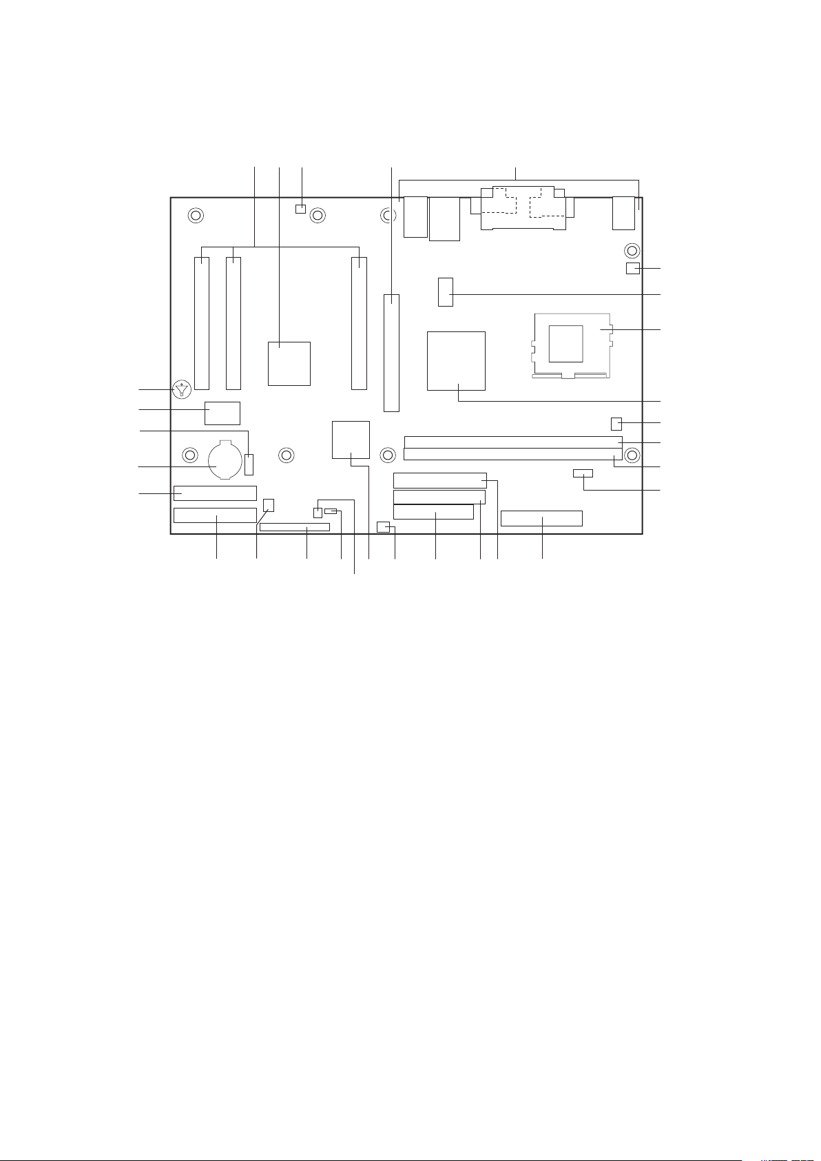
Server Board Connector and Component Locations
Figure 3. Server Board Components
A.
PCI expansion slots
B.
ATI Rage XL Video Controller
C.
D.
E.
F.
G.
H.
I.
J.
K.
L.
M.
N.
Chassis intrusion connector
AGP connector
Back panel connectors
System fan (fan 2)
12 V auxiliary power connector
µPGA478 processor socket
Intel® 82845E memory controller hub (MCH)
Chassis fan
DIMM1 socket
DIMM0 socket
Serial port B connector
Main power connector
P.
Primary IDE connector
Q.
Floppy drive connector
R.
System fan (fan 3)
S.
Intel® 82801BA I/O controller hub (ICH2)
T.
HDD LED connector
U.
Configuration jumper block
V.
Front panel header
W.
System fan (fan 1)
X.
Secondary RAID IDE connector
Y.
Primary RAID IDE connector
Z.
Battery
AA.
Front panel USB connector
BB.
Promise ATA RAID controller connector
CC.
Speaker
10 Description
Page 11

Processors
The Server board board supports a single Intel® Pentium® 4 processor with a µPGA478 socket.
Processors are not included with the server board and must be purchased separately.
Table 2. Supported Processors
Type Designation System Bus L2 Cache Size
Intel® Pentium® 4 processor 1.6, 1.8, 2.0, 2.26, and 2.4 GHz 400 / 533 MHz 512 KB
Intel® Pentium® 4 processor 1.8, 1.9, and 2.0 GHz 400 MHz 256 KB
Intel® Celeron® processor 1.7, 1.8, and 1.9 GHz 400 MHz 128 KB
Memory
The SE845WD1-E server board contains two 184-pin DIMM sockets and supports up to
two DDR SDRAM DIMMs. The minimum supported memory configuration is 64 MB and
the maximum configurable memory size is a 2 GB stacked un-buffered DDR200/266 ECC
DIMM. See the table below for supported memory configurations.
Table 3. Supported Memory Congurations
DIMM Capacity
64 MB SS 64 Mbit 8 M x 8/empty 8
64 MB SS 128 Mbit 8 M x 16/empty 4
128 MB DS 64 Mbit 8 M x 8/8 M x 8 16 (Note 1)
128 MB SS 128 Mbit 16 M x 8/empty 8
128 MB SS 256 Mbit 16 M x 16/empty 4
256 MB DS 128 Mbit 16 M x 8/16 M x 8 16 (Notes 1 and 2)
256 MB SS 256 Mbit 32 M x 8/empty 8
256 MB SS 512 Mbit 32 M x 16/empty 4
512 MB DS 256 Mbit 32 M x 8/32 M x 8 16 (Notes 1 and 2)
512 MB SS 512 Mbit 64 M x 8/empty 8
1024 MB DS 512 Mbit 64 M x 8/64 M X8 16
Notes:
1. If the number of DDR SDRAM devices is greater than nine, the DIMM will be double sided.
2. Front side population/back side population indicated for DDR SDRAM density and DDR SDRAM organization.
Number of
Sides
DDR SDRAM
Density
DDR SDRAM Organization
Front-side/Back-side
Number of DDR
SDRAM Devices
DIMM and memory configurations must adhere to the following:
• 2.5 V (only) 184-pin DDR SDRAM DIMMs with gold-plated contacts
• Unbuffered single-sided or double-sided DIMMs.
• Maximum total system memory: 2 GB; Minimum total system memory: 64 MB
• 200/266 MHz DDR SDRAM DIMMs only
• Serial Presence Detect (SPD)
• Suspend to RAM
• Non-ECC and ECC DIMMs
• Only DIMMs tested and qualified by Intel® or a designated memory test vendor will be
supported on the MAXDATA Platinum Server board. A list of qualified DIMMs will be made
available. Note that all DIMMs are supported by design, but only fully qualified DIMMs will
be supported.
11MAXDATA PLATINUM 100 Server
Page 12

13MAXDATA PLATINUM 100 Server
Intel® 845E Chipset
The Intel® 845E chipset consists of the following devices:
• Intel® 82845E Memory Controller Hub (MCH) with Accelerated Hub Architecture (AHA)
bus
• Intel® 82801BA I/O Controller Hub (ICH2) with AHA bus
• Intel® 82802AB Firmware Hub (FWH)
The MCH is a centralized controller for the system bus, the memory bus, the AGP bus,
and the Accelerated Hub Architecture interface. The ICH2 is a centralized controller for the
board’s I/O paths. The FWH provides the nonvolatile storage of the BIOS.
Intel® 82845E Memory Controller Hub (MCH)
The MCH supports the data integrity features supported by the Intel® Pentium® Pro bus,
including address, request, and response parity. The 845E chipset always generates ECC
data while it is driving the processor data bus, although the data bus ECC can be disabled
or enabled by BIOS. It is enabled by default. The MCH provides the following:
• An integrated Synchronous DRAM memory controller with auto detection of SDRAM.
• Support for ACPI Rev 1.0b compliant power management.
Intel® 82801BA I/O Controller Hub (ICH2)
The Intel® 82801BA ICH2 has these features:
• 33 MHz Peripheral Component Interface (PCI) Local Bus slots supporting PCI specifi cation, Rev 2.2.
• Support for the Low Pin Count (LPC) interface.
• Integrated IDE controller (supports Ultra ATA-66/100 mode and Ultra DMA 33 mode).
• Integrated LAN media access controller.
• Universal Serial Bus Interface with two USB controllers providing two back panel ports,
and the option for two front panel ports, in a Universal Host Controller Interface (UHCI)
implementation.
• Power management logic (ACPI Rev 1.0b compliant).
• Support for the System Management Bus routed to:
− All PCI Slots
− S5 wake from all PCI slots
• Real-Time Clock (with 256-byte battery backed CMOS RAM).
• Supports two Master/DMA devices.
Intel® 82802AB Firmware Hub (FWH)
The Intel® 82802AB Firmware Hub (FWH) includes a 4 megabit symmetrical flash memory
device. Internally, the device is grouped into eight 64 KB blocks that are individually erasable,
lockable, and unlockable. The FWH provides the following:
• System BIOS program
• Logic that enables protection for storing and updating of platform information
12 Description
Page 13

I/O Controller
The SMSC LPC47M102 I/O Controller provides the following features:
• Low pin count (LPC) interface
• 3.3 V operation
• One serial port and one serial port header
• One parallel port with Extended Capabilities Port (ECP) and Enhanced Parallel Port (EPP)
support
• Serial IRQ interface compatible with serialized IRQ support for PCI systems
• PS/2-style mouse and keyboard interfaces
• Interface for two 1.2 MB, 1.44 MB, or 2.88 MB diskette drives
• Intelligent power management, including a programmable wake up event interface
• PCI power management support
• Fan control:
- Four fan control outputs
- Four fan tachometer inputs
The BIOS Setup program provides configuration options for the I/O controller.
Serial Ports
The MAXDATA PLATINUM Server board has one serial port connector and one serial port
header. The serial port A connector is located on the back panel. The serial port B header
is located near the main power connector. The serial ports’ NS16C550-compatible UART
supports data transfers at speeds up to 115.2 kb/s with BIOS support.
Parallel Port
The 25-pin D-Sub parallel port connector is located on the back panel. In the BIOS Setup
program, the parallel port can be set to the following modes:
• Output only (PC AT-compatible mode)
• Bi-directional (PS/2 compatible)
• EPP
• ECP
Diskette Drive Controller
The I/O controller supports two diskette drives that are compatible with the 82077 diskette
drive controller and supports both PC-AT and PS/2 modes.
Keyboard and Mouse Interface
PS/2 keyboard and mouse connectors are located on the back panel. The +5 V lines to these
connectors are protected with a PolySwitch circuit that, like a self-healing fuse, reestablishes
the connection after an overcurrent condition is removed.
13MAXDATA PLATINUM 100 Server
Page 14

15MAXDATA PLATINUM 100 Server
NOTE
The keyboard is supported in the bottom PS/2 connector and the mouse is supported in
the top PS/2 connector. Power to the computer should be turned off before a keyboard or
mouse is connected or disconnected.
The keyboard controller contains the AMI keyboard and mouse controller code, provides the
keyboard and mouse control functions, and supports password protection for power-on/reset.
A power-on/reset password can be specified in the BIOS Setup program.
Hardware Management Subsystem
The Hardware Management features enable the board to be compatible with the Wired for
Management (WfM) specification. The board has several hardware management features,
including the following:
• Fan monitoring
• Thermal and voltage monitoring
• Chassis intrusion detection
Hardware Management ASIC
The Hardware Management ASIC provides low-cost instrumentation capabilities. The features
of the component include:
• Internal ambient temperature sensing
• Remote thermal diode sensing for direct monitoring of processor temperature
• Power supply monitoring (+5 V, +3.3 V, +1.5 V, 3.3 VSB, and Vccp) to detect levels above
or below acceptable values
• SMBus interface
Fan Monitoring
The Hardware Management ASIC provides four fan tachometer inputs. Monitoring can be
implemented using Intel® LANDesk Client Manager or third-party software.
Real-Time Clock, CMOS SRAM, and Battery
The real-time clock provides a time-of-day clock and a multi-century calendar with alarm
features. The real-time clock supports 256 bytes of battery-backed CMOS SRAM in two
banks that are reserved for BIOS use.
A coin-cell battery (CR2032) powers the real-time clock and CMOS memory. When the
computer is not plugged into a wall socket, the battery has an estimated life of three years.
When the computer is plugged in, the standby current from the power supply extends the life
of the battery. The clock is accurate to ± 13 minutes/year at 25 ºC with 3.3 VSB applied.
The time, date, and CMOS values can be specied in the BIOS Setup program. The CMOS
values can be returned to their defaults by using the BIOS Setup program.
NOTE
If the battery and AC power fail, custom defaults, if previously saved, will be loaded into
CMOS RAM at power-on.
14 Description
Page 15

Legacy USB Support
Legacy USB support enables USB devices such as keyboard, mice, and hubs to be used
even when the operating system’s USB drivers are not yet available. Legacy USB support
is used to access the BIOS Setup program, and to install an operating system that supports
USB. By default, Legacy USB support is set to Enabled.
The MAXDATA PLATINUM Server board has two USB 1.1 ports; one USB peripheral can be
connected to each port. For more than two USB devices, an external hub can be connected to
any of the ports. Two of the USB ports are implemented with stacked back panel connectors;
the other two are accessible via the front panel USB header. The MAXDATA PLATINUM
Server board fully supports UHCI and uses UHCI-compatible software drivers.
NOTE
Computer systems that have an unshielded cable attached to a USB port may not meet FCC
Class B requirements, even if no device is attached to the cable. Use shielded cable that
meets the requirements for full-speed devices.
Legacy USB support operates as follows:
1. When the user applies power to the computer, legacy support is disabled.
2. POST begins.
3. Legacy USB support is enabled by the BIOS allowing the user to use a USB keyboard
to enter and configure the BIOS Setup program and the maintenance menu.
4. POST completes.
5. The operating system loads. While the operating system is loading, USB keyboard and
mice are recognized and may be used to configure the operating system. (Keyboard and
mice are not recognized during this period if Legacy USB support was set to Disabled in the
BIOS Setup program.)
6. After the operating system loads the USB drivers, all legacy and non-legacy USB devices
are recognized by the operating system, and Legacy USB support from the BIOS is no
longer used.
To install an operating system that supports USB, verify that Legacy USB support in the
BIOS Setup program is set to Enabled and follow the operating system’s installation instructions.
NOTE
Legacy USB support is for keyboard, mice, and hubs only. Other USB devices are not
supported in legacy mode.
15MAXDATA PLATINUM 100 Server
Page 16

17MAXDATA PLATINUM 100 Server
IDE Support
IDE Interfaces
The ICH2’s IDE controller has two independent bus-mastering IDE interfaces that can be
independently enabled. The IDE interfaces support the following modes:
• Programmed I/O (PIO): processor controls data transfer.
• 8237-style DMA: DMA offloads the processor, supporting transfer rates of up to 16 MB
/sec.
• Ultra DMA: DMA protocol on IDE bus supporting host and target throttling and
transfer rates of up to 33 MB/sec.
• ATA-66: DMA protocol on IDE bus supporting host and target throttling and transfer
rates of up to 66 MB/sec. ATA-66 protocol is similar to Ultra DMA and is device driver
compatible.
• ATA-100: DMA protocol on IDE bus allows host and target throttling. The ICH2’s ATA 100 logic can achieve transfer rates up to 100 MB/sec.
NOTE
ATA-66 and ATA-100 are faster timings and require a specialized cable to reduce reections,
noise, and inductive coupling.
The IDE interfaces also support ATAPI devices (such as CD-ROM drives) and ATA devices
using the transfer modes.
The BIOS supports Logical Block Addressing (LBA) and Extended Cylinder Head Sector (ECHS)
translation modes. The drive reports the transfer rate and translation mode to the BIOS.
The MAXDATA PLATINUM Server board supports Laser Servo (LS-120) diskette technology
through the IDE interfaces. An LS-120 drive can be congured as a boot device by setting
the BIOS Setup program’s Boot menu to one of the following:
• ARMD-FDD (ATAPI removable media device – oppy disk drive)
• ARMD-HDD (ATAPI removable media device – hard disk drive)
BIOS
The MAXDATA PLATINUM Server board uses an Intel®/AMI BIOS that is stored in the
Firmware Hub (FWH) and can be updated using a disk-based program. The FWH contains the
BIOS Setup program, POST, the PCI auto-conguration utility, and Plug and Play support.
The MAXDATA PLATINUM Server board supports system BIOS shadowing, allowing the
BIOS to execute from 64-bit onboard write-protected system memory.
The BIOS displays a message during POST identifying the type of BIOS and a revision code.
The initial production BIOS is identied as PT84510A.86B.
When the MAXDATA PLATINUM Server board’s jumper is set to conguration mode and
the server is powered-up, the BIOS compares the processor version and the microcode
version in the BIOS and reports if the two match.
PCI Auto Configuration
The BIOS can automatically configure PCI devices. PCI devices may be onboard or add-in
cards. Auto configuration lets a user insert or remove PCI cards without having to configure
the system. When a user turns on the system after adding a PCI card, the BIOS automatically
configures interrupts, the I/O space, and other system resources. Any interrupts set to
Available in Setup are considered to be available for use by the add-in card. Auto configuration
information is stored in ESCD format.
16 Description
Page 17

PCI IDE Support
If you select Auto in the BIOS Setup program, the BIOS automatically sets up the two
PCI IDE connectors with independent I/O channel support. The IDE interface supports hard
drives up to ATA-66/100 and recognizes any ATAPI compliant devices, including CD-ROM
drives, tape drives, and Ultra DMA drives.
The BIOS determines the capabilities of each drive and congures them to optimize capacity
and performance. To take advantage of the high capacities typically available today, hard
drives are automatically congured for Logical Block Addressing (LBA) and to PIO Mode 3 or
4, depending on the capability of the drive. You can override the auto-conguration options
by specifying manual conguration in the BIOS Setup program.
To use ATA-66/100 features the following items are required:
• An ATA-66/100 peripheral device
• An ATA-66/100 compatible cable
• ATA-66/100 operating system device drivers
NOTE
ATA-66/100 compatible cables are backward compatible with drives using slower IDE transfer
protocols. If an ATA-66/100 disk drive and a disk drive using any other IDE transfer protocol
are attached to the same cable, the maximum transfer rate between the drives is reduced
to that of the slowest device.
Language Support
The BIOS Setup program and help messages are supported in two languages: US English
and Spanish. Additional languages may be flashed in if desired (German, Italian, and French
available). The default language is US English, which is present unless another language is
selected in the BIOS Setup program.
Custom Splash Screen
During POST, an Intel splash screen is displayed by default. This splash screen can be replaced
with a custom splash screen. A utility is available from Intel to assist with creating a custom
splash screen. The custom splash screen can be programmed into the flash memory using
the BIOS upgrade utility. Information about this capability is available on the Intel Support
World Wide Web site.
Boot Options
In the BIOS Setup program, the user can choose to boot from a diskette drive, hard drives,
CD-ROM, or the network. The default setting is for the diskette drive to be the rst boot device,
the hard drive second, and the ATAPI CD-ROM third. The fourth device is disabled.
CD-ROM and Network Boot
Booting from CD-ROM is supported in compliance to the El Torito bootable CD-ROM format
specification. Under the Boot menu in the BIOS Setup program, ATAPI CD-ROM is listed as a
boot device. Boot devices are defined in priority order. Accordingly, if there is not a bootable
CD in the CD-ROM drive, the system will attempt to boot from the next defined drive.
The network can be selected as a boot device. This selection allows booting from the onboard NIC or a network add-in card with a remote boot ROM installed.
17MAXDATA PLATINUM 100 Server
Page 18

19MAXDATA PLATINUM 100 Server
Booting Without Attached Devices
For use in embedded applications, the BIOS has been designed so that after passing the
POST, the operating system loader is invoked even if the following devices are not present:
• Video adapter
• Keyboard
• Mouse
Fast Booting Systems with Intel® Rapid BIOS Boot
These factors affect system boot speed:
• Selecting and configuring peripherals properly
• Using an optimized BIOS, such as the Intel® Rapid BIOS
Intel® Rapid BIOS Boot
Using the following BIOS Setup program settings reduces the POST execution time. In the
Boot Menu:
• Set the hard disk drive as the first boot device. As a result, the POST does not first seek
a diskette drive, which saves about one second from the POST execution time.
• Disable Quiet Boot, which eliminates display of the logo splash screen. This could save
several seconds of painting complex graphic images and changing video modes.
• Enabled Intel® Rapid BIOS Boot. This feature bypasses memory count and the search for
a diskette drive.
NOTE
It is possible to optimize the boot process to the point where the system boots so quickly
that the Intel logo screen (or a custom logo splash screen) will not be seen. Monitors and
hard disk drives with minimum initialization times can also contribute to a boot time that
might be so fast that necessary logo screens and POST messages cannot be seen.
This boot time may be so fast that some drives might be not be initialized at all. If this
condition should occur, it is possible to introduce a programmable delay ranging from three
to 30 seconds (using the Hard Disk Pre-Delay feature of the Advanced Menu in the IDE
Configuration Submenu of the BIOS Setup program).
BIOS Security Passwords
The BIOS includes security features that restrict whether the BIOS Setup program can be
accessed and who can boot the server. A supervisor password and a user password can be
set for the Setup menu and for booting the server, with the following restrictions:
• The supervisor password gives unrestricted access to view and change all Setup options.
If only the supervisor password is set, pressing <Enter> at the password prompt of
Setup gives the user restricted access to Setup.
• If both the supervisor and user passwords are set, you must enter either the
supervisor password or the user password to access Setup. Setup options are then
available for viewing and changing depending on whether the supervisor or user password
was entered.
• Setting a user password restricts who can boot the server. The password prompt is
displayed before the server is booted. If only the supervisor password is set, the server
boots without asking for a password. If both passwords are set, you can enter either pass word to boot the server.
18 Description
Page 19

Table 4. Supervisor and User Password Functions
Supervisor
Password Set
Neither Can change all
Supervisor
only
User only N/A Can change all
Supervisor and
user set
Note: If no password is set, any user can change all Setup options.
Mode User Mode Setup Options
options (Note)
Can change all
options
Can change all
options
Can change all
options (Note)
Can change a
limited number
of options
options
Can change a
limited number
of options
None None None
Supervisor Password Supervisor None
Enter Password
Clear User Password
Supervisor Password
Enter Password
Password to
Enter Setup
User User
Supervisor or
user
Password
During Boot
Supervisor or
user
System Management BIOS (SMBIOS)
SMBIOS is a Server Management Interface (DMI) compliant method for managing computers
in a managed network.
The main component of SMBIOS is the Management Information Format (MIF) database,
which contains information about the computing system and its components. Using SMBIOS,
a system administrator can obtain the system types, capabilities, operational status, and
installation dates for system components. The MIF database denes the data and provides
the method for accessing this information. The BIOS enables applications such as third-party
management software to use SMBIOS.
The BIOS stores and reports the following SMBIOS information:
• BIOS data, such as the BIOS revision level
• Fixed-system data, such as peripherals, serial numbers, and asset tags
• Resource data, such as memory size, cache size, and processor speed
• Dynamic data, such as event detection and error logging
Non-Plug and Play operating systems, such as Windows® NT, require an additional interface
for obtaining the SMBIOS information. The BIOS supports an SMBIOS table interface for
such operating systems. Using this support, an SMBIOS service-level application running
on a non-Plug and Play operating system can obtain the SMBIOS information.
Power Management Features
Power management is implemented at several levels, including:
• Software support through Advanced Configuration and Power Interface (ACPI)
• Hardware support:
– Power connector
– Fan connectors
– LAN wake capabilities
– Instantly Available PC technology
– Resume on Ring
– Wake from USB
– Wake from PS/2 devices
– Power Management Event (PME#) wake-up support
19MAXDATA PLATINUM 100 Server
Page 20

21MAXDATA PLATINUM 100 Server
Wake on LAN Technology
Network adapters that are PCI 2.2 compliant assert the wake-up signal using the PCI bus
signal PME# (pin A19 on the PCI bus connectors).
CAUTION
For Wake on LAN technology, the 5 V standby line for the power supply must be capable
of providing adequate +5 V standby current. Failure to provide adequate standby current
when implementing Wake on LAN technology can damage the power supply.
CAUTION
If the standby current necessary to support multiple wake events from the PCI and/or USB
buses exceeds power supply capacity, the server board may lose register settings stored
in memory, etc.
Wake on Ring
The operation of Wake on Ring can be summarized as follows:
• Powers up the server from the ACPI S5 state.
• Modem must support PME.
• Requires two calls to access the server:
– The first call powers up the server
– The second call enables access (when the appropriate software is loaded)
• For external modems, hardware on the server board monitors the ring indicate (RI) input
of the serial port.
Resume on Ring
The operation of Resume on Ring can be summarized as follows:
• Resumes operation from the ACPI S1.
• Requires only one call to access the server.
• Detects incoming call similarly for external and internal modems; does not use the Wake
on Ring connector.
• Requires modem interrupt be unmasked for correct operation.
ACPI
ACPI gives the operating system direct control over the power management and Plug and
Play functions of a computer. The use of ACPI with the MAXDATA PLATINUM Server board
requires an operating system that provides full ACPI support. ACPI features include:
• Plug and Play (including bus and device enumeration)
• Power management control of individual devices, add-in boards (some add-in boards
may require an ACPI-aware driver), video displays, and hard disk drives
• Methods for achieving less than 15-watt system operation in the power-on/standby
sleeping state
• A Soft-off feature that enables the operating system to power-off the computer
• Support for multiple wake-up events
• Support for a front panel power and sleep mode switch
20 Description
Page 21

Table 5 lists the system states based on how long the power switch is pressed, depending
on how ACPI is congured with an ACPI-aware operating system.
Table 5. Effects of Pressing the Power Switch
…and the power switch is
If the system is in this state…
Off
(ACPI G2/G5 – Soft off)
On
(ACPI G0 – working state)
On
(ACPI G0 – working state)
Sleep
(ACPI G1 – sleeping state)
Sleep
(ACPI G1 – sleeping state)
pressed for …the system enters this state
Less than four seconds Power-on
(ACPI G0 – working state)
Less than four seconds Soft-off/Standby
(ACPI G1 – sleeping state)
More than four seconds Fail safe power-off
(ACPI G2/G5 – Soft off)
Less than four seconds Wake-up
(ACPI G0 – working state)
More than four seconds Power-off
(ACPI G2/G5 – Soft off)
System States and Power States
Under ACPI, the operating system directs all system and device power state transitions. The
operating system puts devices in and out of low-power states based on user preferences
and knowledge of how devices are being used by applications. Devices that are not being
used can be turned off. The operating system uses information from applications and user
settings to put the system as a whole into a low-power state.
Table 6 lists the power states supported by the Server board board along with the associated
system power targets. See the ACPI specification for a complete description of the various
system and power states.
Table 6. Power States and Targeted System Power
Global States Sleeping States
G0 – working
state
G1 – sleeping
state
G1 – sleeping
state
G1 – sleeping
state
G2/S5 S5 – Soft off. Con-
G3 – mechanical
off
AC power is
disconnected from
the computer.
S0 – working C0 – working D0 – working state. Full power > 30 W
S1 – Processor
stopped
S3 – Suspend to
RAM. Context
saved to RAM.
S4 – Suspend to
disk. Context saved
to disk.
text not saved. Cold
boot is required.
No power to the
system.
Processor
States Device States
C1 – stop
grant
No power D3 – no power
No power D3 – no power
No power D3 – no power
No power D3 – no power
D1, D2, D3 – device specification
specific.
except for wake-up
logic.
except for wake-up
logic.
except for wake-up
logic.
for wake-up logic,
except when provided by battery or
external source.
Targeted System
Power (Note 1)
5 W < power < 52.5 W
Power < 5 W (Note 2)
Power < 5 W (Note 2)
Power < 5 W (Note 2)
No power to the system.
Service can be performed
safely.
Notes:
1. Total system power is dependent on the system conguration, including add-in boards and peripherals
powered by the system chassis’ power supply.
2. Dependent on the standby power consumption of wake-up devices used in the system.
21MAXDATA PLATINUM 100 Server
Page 22

23MAXDATA PLATINUM 100 Server
Wake-up Devices and Events
Table 7 lists the devices or specific events that can wake the computer from specific states.
Table 7. Wake-up Devices and Event
These devices/events can wake up the computer… …from this state
Power switch S1, S3, S4, S5
RTC alarm S1, S3, S4, S5
LAN S1, S3, S4, S5 (Note 1)
CNR S1, S3, S4 (Note 2), S5 (Note 2)
PME# S1, S3, S4, S5
Modem (back panel Serial Port A) S1, S3
USB S1, S3
Notes:
1. S4 state is dependent on an OS that supports this wake event.
2. For LAN and PME#, S5 is disabled by default in the BIOS Setup program. Setting this option to Power On will enable a
wake-up event from LAN in the S5 state.
NOTE
The use of these wake-up events from an ACPI state requires an operating system that
provides full ACPI support. In addition, software, drivers, and peripherals must fully support
ACPI wake events.
Hardware Support
The MAXDATA PLATINUM Server board provides several power management hardware
features, including:
• Power connector
• Fan connectors
• LAN wake capabilities
• Instantly Available PC technology
• Resume on Ring
• Wake from USB
• Wake from PS/2 keyboard
• PME# wake-up support
LAN wake capabilities and Instantly Available PC technology require power from the +5 V
standby line. The sections discussing these features describe the incremental standby power
requirements for each.
Resume on Ring enables telephony devices to access the computer when it is in a powermanaged state. The method used depends on the type of telephony device (external or
internal).
CAUTION
Ensure that the power supply provides adequate +5 V standby current if LAN wake capabilities
and Instantly Available PC technology features are used. Failure to do so can damage the
power supply. The total amount of standby current required depends on the wake devices
supported and manufacturing options.
NOTE
The use of Resume on Ring and Wake from USB technologies from an ACPI state requires
an operating system that provides full ACPI support.
22 Description
Page 23

Power Connector
When used with an ATX12V or EPS-12 V compliant power supply that supports remote
power on/off, the MAXDATA PLATINUM Server board can turn off the system power through
software control. When the system BIOS receives the correct command from the operating
system, the BIOS turns off power to the computer.
With soft-off enabled, if power to the computer is interrupted by a power outage or a
disconnected power cord, when power resumes, the computer returns to the power state it
was in before power was interrupted (on or off). The computer’s response can be set using
the After Power Failure feature in the BIOS Setup program’s Boot menu.
Fan Connectors
Table 8 summarizes the function/operation of the fan connectors.
Table 8. Fan Connector Function/Operation
Connector Description
Processor fan (CPU
FAN)
Front and rear chassis
fans (FAN1, FAN2,
and FAN3)
• +12 V DC connection for a processor fan or active fan heat sink.
• Fan is on in the S0 or S1 state. Fan is off when the system is off or in the S3,
S4, or S5 state.
• Wired to a fan tachometer input of the Hardware Management ASIC.
• +12 V DC connection for a system or chassis fan.
• Fan is on in the S0 or S1 state. Fan is off when the system is off or in the S3,
S4, or S5 state.
• Wired to a fan tachometer input of the Hardware Management ASIC.
LAN Wake Capabilities
CAUTION
For LAN wake capabilities, the 5 V standby line for the power supply must be capable of
providing adequate +5 V standby current. Failure to provide adequate standby current when
implementing LAN wake capabilities can dama e the power supply.
LAN wake capabilities enable remote wake-up of the computer through a network. The LAN
subsystem PCI bus network adapter monitors network trafc at the Media Independent
Interface. Upon detecting a Magic Packet frame, the LAN subsystem asserts a wake-up
signal that powers up the computer.
Depending on the LAN implementation, the MAXDATA PLATINUM Server board supports
LAN wake capabilities with ACPI in the following ways:
• The PCI bus PME# signal for PCI 2.2 compliant LAN designs
• The onboard LAN subsystem
Instantly Available PC Technology
CAUTION
For Instantly Available PC technology, the +5 V standby line for the power supply must be capable of providing adequate +5 V standby current. Failure to provide adequate standby current
when implementing Instantly Available PC technology can damage the power supply.
The MAXDATA PLATINUM Server board supports the PCI Bus Power Management Interface
Specication. Add-in Board that also support this specication can participate in power
management and can be used to wake the computer.
The use of Instantly Available PC technology requires operating system support and PCI 2.2
compliant add-in cards and drivers.
23MAXDATA PLATINUM 100 Server
Page 24
25MAXDATA PLATINUM 100 Server
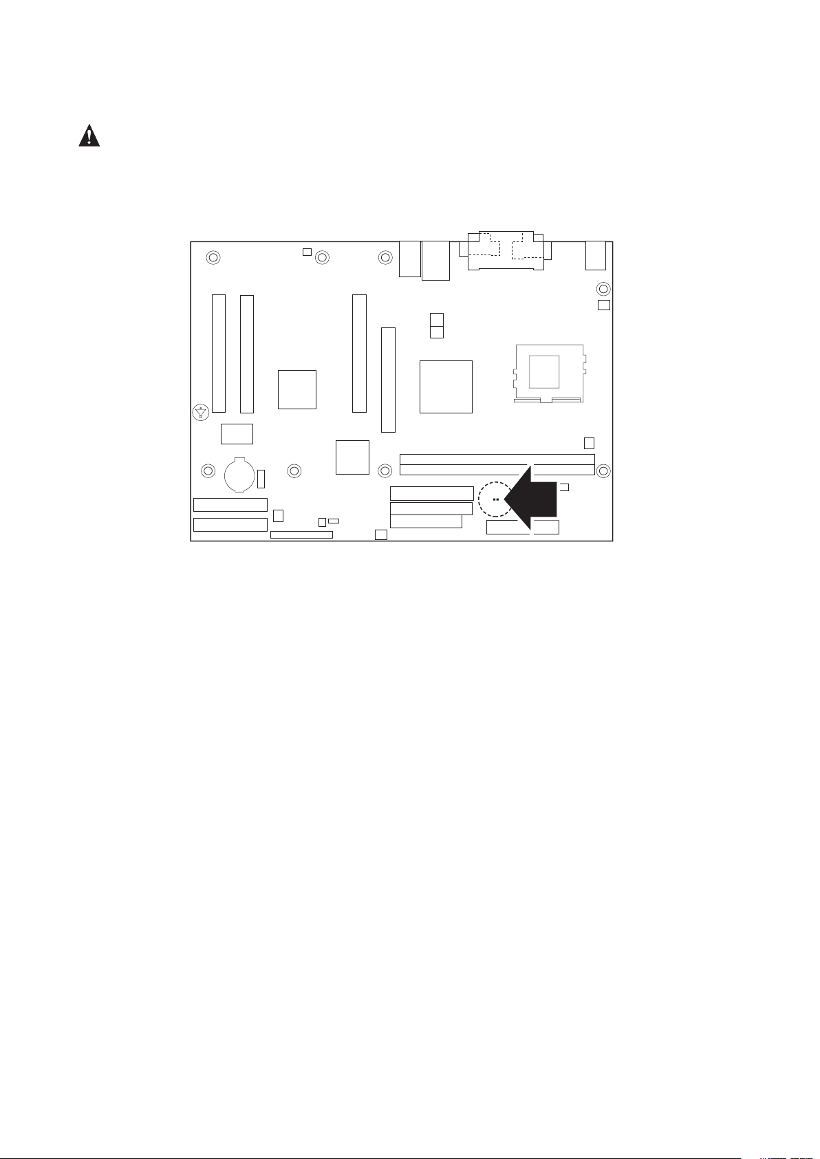
The standby power indicator LED shows that power is still present even when the computer
CR3G1
appears to be off. Figure 4 shows the location of the standby power indicator LED.
CAUTION
If AC power has been switched off and the standby power indicator is still lit, disconnect
the power cord before installing or removing any devices connected to the board. Failure to
do so could damage the board and any attached devices.
Figure 4. Location of the Standby Power Indicator LED
Resume on Ring
The operation of Resume on Ring can be summarized as follows:
• Resumes operation from ACPI S1 state
• Requires only one call to access the computer
• Detects incoming call similarly for external and internal modems
• Requires modem interrupt be unmasked for correct operation
Wake from USB
USB bus activity wakes the computer from an ACPI S1 state.
NOTE
Wake from USB requires the use of a USB peripheral that supports Wake from USB.
Wake from PS/2 Devices
PS/2 device activity wakes the computer from an ACPI S1 state.
PME# Wake-up Support
When the PME# signal on the PCI bus is asserted, the computer wakes from an ACPI S1,
S4, or S5 state (with Wake on PME enabled in BIOS).
24 Description
Page 25

PCI I/O Subsystem
The primary I/O bus for the MAXDATA PLATINUM Server board is PCI, with one independent
PCI bus. The PCI bus complies with the PCI Local Bus Specication, Rev 2.2. The PCI bus
is directed through the Intel® 82801BA I/O Controller Hub (ICH2). The table below lists the
characteristics of the PCI bus.
Table 9. PCI Bus Characteristics
Voltage Width Speed Type Comments
5 V 32-bits 33 MHz Independent Bus Supports full-length
cards
32-bit, 33-MHz PCI Subsystem
All 32-bit, 33-MHz PCI I/O for the MAXDATA PLATINUM Server board is directed through
the Intel® 82801BA I/O Controller Hub (ICH2). The PCI bus supports the following embedded
devices and connectors:
• 2D/3D Graphics Accelerator: ATI Rage XL Video Controller.
• Two 10/100 Network Interface Controllers: Intel® 82550PM Fast Ethernet Controller.
• ATA-100 controller: Promise Technology PDC20267.
• Two Ultra DMA 33 / ATA 66/100 connectors.
Each of the embedded devices listed above, with exception to the Ultra DMA 33 / ATA
66/100 connectors, will be allocated a GPIO to disable the device.
Device IDs (IDSEL)
Each device under the PCI hub bridge has its IDSEL signal connected to one bit of AD[31:16],
which acts as a chip select on the PCI bus segment in configuration cycles. This determines
a unique PCI device ID value for use in configuration cycles. The following table shows each
IDSEL value for the PCI bus devices and the corresponding device description.
Table 10. PCI Bus Conguration IDs
IDSEL Value Device
25 PCI slot 1 (closest to AGP connector)
26 PCI slot 2 (middle slot)
27 PCI slot 3 (closest to left edge of board)
28 Intel® 82550PM Fast Ethernet Controller
29 Intel® 82550PM Fast Ethernet Controller
30 ATA-100 controller Promise Technology PDC20267
31 ATI Rage XL Video Controller
PCI Arbitration
The PCI bus supports six PCI masters (ATI Rage XL, two Intel® 82550s, Promise ATA-100
Controller, PCI connector 1 and an arbiter (PCI connector 2 and PCI connector 3). All PCI
masters must arbitrate for PCI access, using resources supplied by the ICH2. The host
bridge PCI interface (ICH2) arbitration lines REQx and GNTx are a special case in that they
are internal to the host bridge.
25MAXDATA PLATINUM 100 Server
Page 26

27MAXDATA PLATINUM 100 Server
ATA-100
The MAXDATA PLATINUM Server board provides an embedded dual channel ATA-100
bus through the use of the Promise Technology PDC20267 ASIC. The PDC20267 ATA-100
controller contains two independent ATA-100 channels that share a single 32-bit, 33-MHz
PCI bus master interface as a multifunction device, packaged in a 128-pin PQFP.
The ATA-100 controller supports the following features:
• The scatter / gather mechanism supports both Direct Memory Access (DMA) and Pro-
grammable I/O (PIO) IDE drives and ATAPI devices.
• Support for ATA and ATAPI proposal PIO Mode 0, 1, 2, 3, 4, DMA Mode 0, 1, 2, and
Ultra DMA Mode 0, 1, 2, 3, 4, 5.
• The IDE drive transfer rate is capable of up to 100 MB/sec per channel.
• The host interface complies with PCI Local Bus Specification Revision 2.2.
• 32-bit, 33-MHz bus speed and 132 MB/sec sustained transfer rate.
The Promise PDC20267 supports IDE RAID through dual ATA-100 Channels. In a RAID
configuration, multiple IDE hard drives are placed into one or more arrays of disks. Each
array is seen as an independent disk, though the array may include upwards of two, three,
or four drives. The IDE RAID can be configured as follows:
• RAID 0: Striping one to four drives.
• RAID 1: Mirroring two drives.
• RAID 1 +: Spare drive (three drives).
• RAID 0 +: One to four drives are required.
RAID 0 configurations are used for high-performance applications, as it doubles the sustained
transfer rate of its drives. RAID 1 configurations primarily used for data protection. It creates
an identical drive backup to a secondary drive. Whenever a disk write is performed, the
controller sends data simultaneously to a second drive located on a different data channel.
With four drives attached to dual ATA-100 channels, two striped drive pairs can mirror each
other (RAID 0+1) for storage capacity and data redundancy.
Video Controller
The MAXDATA PLATINUM Server board provides an ATI Rage XL PCI graphics accelerator, along with 8 MB of video SDRAM and support circuitry for an embedded SVGA video
subsystem. The ATI Rage XL chip contains a SVGA video controller, clock generator, 2D
and 3D engine, and RAMDAC in a 272-pin PBGA. Four 2Mx32 SDRAM chip provides 8 MB
of video memory.
The SVGA subsystem supports a variety of modes, up to 1600 x 1200 resolution in 8/16/24/32
bpp modes under 2D, and up to 1024 x 768 resolution in 8/16/24/32 bpp modes under 3D.
It also supports both CRT and LCD monitors up to 100 Hz vertical refresh rate.
The MAXDATA PLATINUM Server board provides a standard 15-pin VGA connector and
supports disabling of the on-board video through the BIOS Setup menu or when a plug-in
video card is installed in the AGP slot or any of the PCI slots.
26 Description
Page 27

Video Modes
The Rage XL chip supports all standard IBM VGA modes. The following table shows the
2D/3D modes supported for both CRT and LCD. The table specifies the minimum memory
requirement for various display resolution, refresh rates, and color depths.
Table 11. Video Modes
MPL 2D Video Mode Support
2D Mode Refresh Rate (Hz)
640x480 60, 72, 75, 90, 100 Supported Supported Supported Supported
800x600 60, 70, 75, 90, 100 Supported Supported Supported Supported
1024x768 60, 72, 75, 90, 100 Supported Supported Supported Supported
1280x1024 43, 60 Supported Supported Supported Supported
1280x1024 70, 72 Supported – Supported Supported
1600x1200 60, 66 Supported Supported Supported Supported
1600x1200 76, 85 Supported Supported Supported –
3D Mode Refresh Rate (Hz) MPL 3D Video Mode Support with Z Buffer Enabled
640x480 60,72,75,90,100 Supported Supported Supported Supported
800x600 60,70,75,90,100 Supported Supported Supported Supported
1024x768 60,72,75,90,100 Supported Supported Supported Supported
1280x1024 43,60,70,72 Supported Supported – –
1600x1200 60,66,76,85 Supported – – –
8 bpp 16 bpp 24 bpp 32 bpp
Video Memory Interface
The memory controller subsystem of the Rage XL arbitrates requests from direct memory
interface, the VGA graphics controller, the drawing coprocessor, the display controller, the
video scalar, and hardware cursor. Requests are serviced in a manner that ensures display
integrity and maximum CPU/coprocessor drawing performance.
The server board supports a 8 MB (2048K x 32bit x 4 Banks) SDRAM device for video
memory.
Network Interface Controller (NIC)
The MAXDATA PLATINUM Server board supports two 10Base-T/100Base-TX Network Interface
Controllers (NICs) based on the Intel® 82550PM NIC. The 82550PM is a highly integrated PCI
LAN controller in a thin BGA 15mm package. The controller’s baseline functionality is equivalent
to that of the Intel® 82559, with the addition of Alert-on-LAN functionality. The MAXDATA
PLATINUM Server board supports independent disabling of the two NIC controllers using the
BIOS Setup menu. The 82550PM supports the following features:
• Glueless 32-bit PCI, CardBus master interface (Direct Drive of Bus), compatible with
PCI local Bus Specication, Revision 2.2.
• Integrated IEEE 802.3 10Base-T and 100Base-TX compatible PHY.
• IEEE 820.3u auto-negotiation support.
• Full duplex support at both 10 Mbps and 100 Mbps operation.
• Integrated UNDI ROM support.
• MDI/MDI-X and HWI support.
• Low power +3.3 V device.
27MAXDATA PLATINUM 100 Server
Page 28

NIC Connector and Status LEDs
The 82550 drives two LEDs located on each network interface connector. The amber LED
indicates network connection when on, and transmit/receive activity when blinking. The
yellow LED indicates 100-Mbps operation when lit, and 10-Mbps when off.
Hardware Monitoring
The MAXDATA PLATINUM Server board has an integrated Hardware Management ASIC
that is responsible for hardware monitoring. Together, the Hardware Management ASIC and
the Intel® LANDesk® Client Manager (LDCM) 6.3 software provide basic server hardware
monitoring which alerts a system administrator if a hardware problem occurs on an Intel
Server board based system. The Intel® LDCM software is for use with Windows® 2000 Server
and Windows® 2000 Advanced Server operating systems. Other Server board operating
systems like Red Hat Linux won’t be monitored with LDCM.
®
28 Description 29MAXDATA PLATINUM 100 Server
Page 29
3 Regulatory and Integration Information
Product Regulatory Compliance
Product Safety Compliance
The Server board complies with the following safety requirements:
• UL 1950 - CSA 950 (US/Canada)
• EN 60 950 (European Union)
• IEC60 950 (International)
• CE – Low Voltage Directive (73/23/EEC) (European Union)
Product EMC Compliance
The Server board has been has been tested and verified to comply with the following
electromagnetic compatibility (EMC) regulations when installed a compatible Intel® host
system.
• FCC (Class A Verification) – Radiated & Conducted Emissions (USA)
• CISPR 22, 3rd Edition (Class A) – Radiated & Conducted Emissions (International)
• EN55022 (Class A) – Radiated & Conducted Emissions (European Union)
• EN55024 (Immunity) (European Union)
• CE – EMC Directive (89/336/EEC) (European Union)
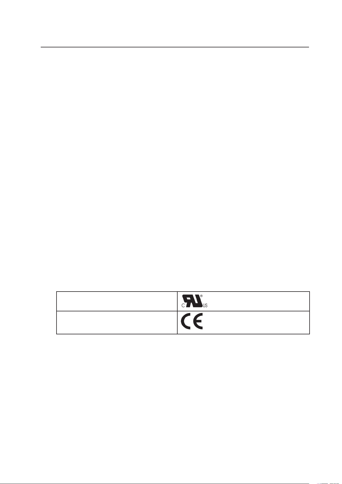
Product Regulatory Compliance Markings
This product is marked with the following Product Certication Markings:
Table 12. Product Certication Markings
UL Recognition Mark
CE Mark
Page 30

31MAXDATA PLATINUM 100 Server
Electromagnetic Compatibility Notices
FCC (USA)
This device complies with Part 15 of the FCC Rules. Operation is subject to the following two
conditions: (1) this device may not cause harmful interference, and (2) this device must accept
any interference received, including interference that may cause undesired operation.
This equipment has been tested and found to comply with the limits for a Class A digital
device, pursuant to Part 15 of the FCC Rules. These limits are designed to provide reasonable
protection against harmful interference in a residential installation. This equipment generates,
uses, and can radiate radio frequency energy and, if not installed and used in accordance with
the instructions, may cause harmful interference to radio communications. However, there
is no guarantee that interference will not occur in a particular installation. If this equipment
does cause harmful interference to radio or television reception, which can be determined
by turning the equipment off and on, the user is encouraged to try to correct the interference
by one or more of the following measures:
• Reorient or relocate the receiving antenna.
• Increase the separation between the equipment and the receiver.
• Connect the equipment to an outlet on a circuit other than the one to which the receiver
is connected.
• Consult the dealer or an experienced radio/TV technician for help.
Any changes or modifications not expressly approved by the grantee of this device could
void the user’s authority to operate the equipment. The customer is responsible for ensuring
compliance of the modified product.
Only peripherals (computer input/output devices, terminals, printers, etc.) that comply
with FCC Class A or B limits may be attached to this computer product. Operation with
noncompliant peripherals is likely to result in interference to radio and TV reception.
All cables used to connect to peripherals must be shielded and grounded. Operation with
cables, connected to peripherals, that are not shielded and grounded may result in interference
to radio and TV reception.
Europe (CE Declaration of Conformity)
This product has been tested in accordance to, and complies with the Low Voltage Directive
(73/23/EEC) and EMC Directive (89/336/EEC). The product has been marked with the CE
Mark to illustrate its compliance.
30 Regulatory and Integration Information
Page 31

Installation Precautions
When you install and test the server board, observe all warnings and cautions in the installation
instructions.
To avoid injury, be careful of:
• Sharp pins on connectors
• Sharp pins on printed circuit assemblies
• Rough edges and sharp corners on the chassis
• Hot components (like processors, voltage regulators, and heat sinks)
• Damage to wires that could cause a short circuit
Observe all warnings and cautions that instruct you to refer computer servicing to qualified
technical personnel.
Installation Requirements
CAUTION
Follow these guidelines to meet safety and regulatory requirements when installing this
board assembly.
Read and adhere to all of these instructions and the instructions supplied with the chassis and
associated modules. If the instructions for the chassis are inconsistent with these instructions
or the instructions for associated modules, contact the supplier’s technical support to find
out how you can ensure that your computer meets safety and regulatory requirements. If
you do not follow these instructions and the instructions provided by chassis and module
suppliers, you increase safety risk and the possibility of noncompliance with regional laws
and regulations.
Prevent Power Supply Overload
Do not overload the power supply output. To avoid overloading the power supply, make sure
that the calculated total current loads of all the modules within the computer is less than
the output current rating of each of the power supplies output circuits.
Place Battery Marking
There is insufcient space on this server board to provide instructions for replacing and
disposing of the battery. For system safety certication, the following statement or equivalent
statement may be required to be placed permanently and legibly on the chassis near the
battery.
CAUTIONS
Risk of explosion if battery is incorrectly replaced.
Replace with only the same or equivalent type recommended by the manufacturer. Dispose
of used batteries according to the manufacturer’s instructions.
Use Only for Intended Applications
This server was evaluated as Information Technology Equipment (I.T.E.) for use in computers
that will be installed in ofces, homes, schools, computer rooms, and similar locations. The
suitability of this product for other applications or environments, (such as medical, industrial,
alarm systems, test equipment, etc.) may require further evaluation.
31MAXDATA PLATINUM 100 Server
 Loading...